EP1466646A1 - Sicherheitsvorrichtung gegen freier Strömung - Google Patents
Sicherheitsvorrichtung gegen freier Strömung Download PDFInfo
- Publication number
- EP1466646A1 EP1466646A1 EP03405252A EP03405252A EP1466646A1 EP 1466646 A1 EP1466646 A1 EP 1466646A1 EP 03405252 A EP03405252 A EP 03405252A EP 03405252 A EP03405252 A EP 03405252A EP 1466646 A1 EP1466646 A1 EP 1466646A1
- Authority
- EP
- European Patent Office
- Prior art keywords
- crushing
- flexible conduit
- liquid
- jaws
- pressure
- Prior art date
- Legal status (The legal status is an assumption and is not a legal conclusion. Google has not performed a legal analysis and makes no representation as to the accuracy of the status listed.)
- Withdrawn
Links
Images

Classifications
-
- A—HUMAN NECESSITIES
- A61—MEDICAL OR VETERINARY SCIENCE; HYGIENE
- A61M—DEVICES FOR INTRODUCING MEDIA INTO, OR ONTO, THE BODY; DEVICES FOR TRANSDUCING BODY MEDIA OR FOR TAKING MEDIA FROM THE BODY; DEVICES FOR PRODUCING OR ENDING SLEEP OR STUPOR
- A61M39/00—Tubes, tube connectors, tube couplings, valves, access sites or the like, specially adapted for medical use
- A61M39/22—Valves or arrangement of valves
- A61M39/28—Clamping means for squeezing flexible tubes, e.g. roller clamps
- A61M39/281—Automatic tube cut-off devices, e.g. squeezing tube on detection of air
-
- A—HUMAN NECESSITIES
- A61—MEDICAL OR VETERINARY SCIENCE; HYGIENE
- A61M—DEVICES FOR INTRODUCING MEDIA INTO, OR ONTO, THE BODY; DEVICES FOR TRANSDUCING BODY MEDIA OR FOR TAKING MEDIA FROM THE BODY; DEVICES FOR PRODUCING OR ENDING SLEEP OR STUPOR
- A61M2202/00—Special media to be introduced, removed or treated
- A61M2202/04—Liquids
- A61M2202/0468—Liquids non-physiological
- A61M2202/0482—Enteral feeding product
-
- A—HUMAN NECESSITIES
- A61—MEDICAL OR VETERINARY SCIENCE; HYGIENE
- A61M—DEVICES FOR INTRODUCING MEDIA INTO, OR ONTO, THE BODY; DEVICES FOR TRANSDUCING BODY MEDIA OR FOR TAKING MEDIA FROM THE BODY; DEVICES FOR PRODUCING OR ENDING SLEEP OR STUPOR
- A61M5/00—Devices for bringing media into the body in a subcutaneous, intra-vascular or intramuscular way; Accessories therefor, e.g. filling or cleaning devices, arm-rests
- A61M5/14—Infusion devices, e.g. infusing by gravity; Blood infusion; Accessories therefor
- A61M5/142—Pressure infusion, e.g. using pumps
- A61M5/14212—Pumping with an aspiration and an expulsion action
- A61M5/14232—Roller pumps
Definitions
- the present invention relates to a new device device to stop the free flow of a liquid in a flexible duct.
- U.S. Patent No. 6,461,335 or No. 6,494,864 by example describes a valve placed inside the duct flexible arranged to open automatically under the effect of the tensile force transmitted to the part of the duct flexible upstream of the valve by liquid pressure when the pump is working properly, and close again as soon as this pressure is below a certain threshold.
- the positioning of this valve inside the duct flexible is not easy to achieve under conditions sterile.
- U.S. Patent No. 4,689,043 provides a device to be positioned around the flexible duct comprising crushing means thereof, which can be actuated by a handle so as to close off the duct when the pump does not work correctly. This device is structured complicated and is not automated.
- U.S. Patent No. 5,423,759 describes another device which includes means for crushing the duct flexible, arranged to seal the duct as soon as the pressure liquid is less than a given value, and a sensor electronic pressure which measures this pressure in upstream of the device, compare it to a reference value and sends signals to control the crushing means.
- This device includes an electronic part capable of and costly.
- the problem or object of the invention is to provide a safety device against free flow which does not not have the above-mentioned drawbacks.
- the invention relates to a safety device for stop the free flow of a liquid in a conduit flexible which includes means for crushing the duct flexible, characterized in that these means of crushing the flexible conduit are elastic means calibrated so as not to allow the passage of liquid only when the pressure of the liquid exceeds a given value.
- the calibrated elastic means include a pair of arms elastic, each of these arms carrying a jaw of crushing and a support surface. These elastic arms are subjected to an initial bending preload sufficient for the crushing jaws to block the flexible duct. These bearing surfaces located near the inlet of the device and in contact with the flexible conduit transmit to the elastic arms a force proportional to the pressure of the liquid upstream of the device.
- the crush jaws only open when this force exceeds the initial bending preload of the arms. We chooses this prestress so as not to allow this opening only when the liquid pressure exceeds a given threshold value, between pressure free flow and liquid pressure when the pump is working properly. So the device will stop the liquid in case of free flow and will let it pass when the pump is working properly.
- the initial bending preload of the arms depends of their geometry and properties, in particular the modulus of elasticity of the material which constitutes them. We has formulas for calculating dimensions arms for a given material.
- the device can be made of a material plastic such as polypropylene, polyethylene high density, polystyrene, polyvinyl chloride, a styrene-butadiene copolymer or an acrylonitrile-butadiene-styrene copolymer. It is then conveniently manufactured by injection molding.
- a material plastic such as polypropylene, polyethylene high density, polystyrene, polyvinyl chloride, a styrene-butadiene copolymer or an acrylonitrile-butadiene-styrene copolymer.
- the device can also be made of a metal such than aluminum or stainless steel, in particular stainless spring steel.
- It can in particular be made from a wire stainless steel with spring, or be formed or folded from a metal sheet or sheet.
- the security device includes gripping elements for manual action on the jaws of crushing so as to temporarily allow the passage of the liquid, for example to allow priming of the administration line.
- the device includes means for precisely controlling the opening crushing jaws so as to regulate the liquid flow.
- These means may include, for example a finger driven by a slide that fits between the crushing jaws.
- the same device can then serve either to regulate the flow of liquid, in a similar manner roller clamp, when not in use no pump, either to protect against free flow when using a pump.
- the security device of the invention can be used in all applications where a risk exists in liquid passing below a given value of pressure.
- the use of the device of the invention presents a particular interest in the medical field in particular for administering saline solutions to patients glucose, aqueous nutritious or medicinal formulations, saline or glucose solution, or solution isotonic enterally or parenterally.
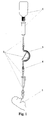
- Figure 1 shows a raised liquid tank 1 from which a flexible conduit 2 leaves, a segment of which passes through a peristaltic pump 3 which sends a controlled flow of liquid to patient 5 and another segment passes in the safety device according to the invention 4 located between pump 3 and patient 5.
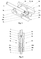
- the safety device 4 shown in the figures 3 and 4 comprises two substantially symmetrical halves 4a, 4b, which each have a parallelepipedic body 5a, 5b. These bodies 5a, 5b are assembled as illustrated by the Figure 4 and fixed to each other by appropriate means such as by welding, clipping or screwing for example. Each parallelepiped body 5a, 5b is integral with a elastic arm 6a, 6b carrying at its end a jaw of substantially triangular section 7a, 7b defining a crushing line transverse to flexible conduit 2.
- Each elastic arm still has a bearing surface 8a, 8b intended to deform the section of the flexible conduit 2 so to have a large contact surface between this flexible conduit 2 and the bearing surfaces 8a, 8b, to allow good transmission of duct pressure flexible 2 with elastic arms 6a, 6b.
- Two gripping elements 9a, 9b extend along two lateral edges respective opposites of the bearing surfaces 8a, 8b.
- Each parallelepipedic body 5a, 5b has a semi-cylindrical recess 20a, 20b whose longitudinal profile is substantially complementary to that of a connector 21 intended to join two segments of the flexible conduit 2.
- This connector 21 has an annular flange 21a intended to be housed in a corresponding portion 20a 1 , 20b 1 of the semi-cylindrical recesses 20a, 20b to form an anchorage between the safety device and the flexible conduit 2.
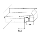
- the dimensions of the elastic arms 6a, 6b can be calculated from the following equations. The main forces and other parameters important for this calculation are shown in Figure 2.
- ⁇ M ext 0 in which F preload : initial tension force generated by bending the arm
- F occlusion force necessary to ensure occlusion
- F tube force due to the slight tightening applied to the tube
- F opening force due to the pressure applied to the flat surface
- L total length of the moving part 1: flexible arm length l useful : length of the surface allowing the opening
- the gripping elements 9a, 9b allow, if necessary, to manually separate the jaws 7a, 7b from way to open the safety device momentarily and reversibly, for example to expel air during priming of the liquid administration line (priming).
- the device 10 according to the second embodiment shown in Figures 5 and 6 has a hollow body elongated 17 of rectangular U-shaped section, intended to receive the flexible conduit 2.
- This elongated hollow body 17 ends at one end with two elastic arms 11a, 11b which have a pair of jaws 12a, 12b, of section substantially triangular, each defining a line of transverse crushing to the flexible duct 2.
- a pair of bearing surfaces 13a, 13b extend beyond the jaws 12a, 12b. These bearing surfaces 13a, 13b are intended to slightly deform the section of flexible conduit 2 so to have a large contact surface between this flexible conduit 2 and these bearing surfaces 13a, 13b, for allow good transmission of duct pressure flexible 2 with elastic arms 11a, 11b.
- a slide 16 comprising a gripping projection 16a is slidably mounted on the elongated body 17 and closes the opening of its U-shaped section.
- This slide 16 carries a substantially triangular finger 15 capable of being inserted between the jaws 12a, 12b during the movement of the slide 16 in the direction of the jaws 12a, 12b so to spread them manually.
- This device can be used either to adjust with precision the flow of the liquid using the slide 16 and of the triangular finger 15, analogously to the pliers roller clamps used conventionally, either to stop the free flow depending on the pressure exerted by the flexible conduit 2 via bearing surfaces 13a, 13b.
- This result could also be obtained for example by conforming the side faces of the triangular finger 15 so as to induce a slight torsion when it acts on the elastic arms 11a, 11b.
- the device safety according to the invention could comprise a single arm elastic 6a or 6b, 11a or 11b.
- the elastic arms can be either manually deformable beyond the elastic limit, either breakable manually to remove the function device security, in case you want to use the tubing with which the safety device is associated with gravity flow and not by a pump.
- the safety device described in both forms of execution is shown to work in one direction flow in conduit 2.
- the surface of these second bearing surfaces could be different, so that conduit 2 opens at different pressures depending on the direction of the flow in this conduit 2.
Landscapes
- Health & Medical Sciences (AREA)
- Heart & Thoracic Surgery (AREA)
- Pulmonology (AREA)
- Engineering & Computer Science (AREA)
- Anesthesiology (AREA)
- Biomedical Technology (AREA)
- Hematology (AREA)
- Life Sciences & Earth Sciences (AREA)
- Animal Behavior & Ethology (AREA)
- General Health & Medical Sciences (AREA)
- Public Health (AREA)
- Veterinary Medicine (AREA)
- Infusion, Injection, And Reservoir Apparatuses (AREA)
Priority Applications (1)
| Application Number | Priority Date | Filing Date | Title |
|---|---|---|---|
| EP03405252A EP1466646A1 (de) | 2003-04-10 | 2003-04-10 | Sicherheitsvorrichtung gegen freier Strömung |
Applications Claiming Priority (1)
| Application Number | Priority Date | Filing Date | Title |
|---|---|---|---|
| EP03405252A EP1466646A1 (de) | 2003-04-10 | 2003-04-10 | Sicherheitsvorrichtung gegen freier Strömung |
Publications (1)
| Publication Number | Publication Date |
|---|---|
| EP1466646A1 true EP1466646A1 (de) | 2004-10-13 |
Family
ID=32865105
Family Applications (1)
| Application Number | Title | Priority Date | Filing Date |
|---|---|---|---|
| EP03405252A Withdrawn EP1466646A1 (de) | 2003-04-10 | 2003-04-10 | Sicherheitsvorrichtung gegen freier Strömung |
Country Status (1)
| Country | Link |
|---|---|
| EP (1) | EP1466646A1 (de) |
Cited By (6)
| Publication number | Priority date | Publication date | Assignee | Title |
|---|---|---|---|---|
| EP2008681A1 (de) | 2007-06-29 | 2008-12-31 | F.Hoffmann-La Roche Ag | Vorrichtung zur Verhinderung eines freien Katheterdurchflusses |
| EP2218476A1 (de) * | 2009-02-11 | 2010-08-18 | F. Hoffmann-La Roche AG | Blattfederventil und Konusmembranventil |
| US8377000B2 (en) | 2010-10-01 | 2013-02-19 | Abbott Laboratories | Enteral feeding apparatus having a feeding set |
| US8377001B2 (en) | 2010-10-01 | 2013-02-19 | Abbott Laboratories | Feeding set for a peristaltic pump system |
| US8689439B2 (en) | 2010-08-06 | 2014-04-08 | Abbott Laboratories | Method for forming a tube for use with a pump delivery system |
| WO2019048255A1 (en) * | 2017-09-11 | 2019-03-14 | Fresenius Vial Sas | CLAMPING CLAMP DEVICE |
Citations (4)
| Publication number | Priority date | Publication date | Assignee | Title |
|---|---|---|---|---|
| EP0423978A2 (de) * | 1989-10-20 | 1991-04-24 | Minnesota Mining And Manufacturing Company | System zur Verhinderung eines freien Durchflusses in einer Infusionspumpe |
| US5154704A (en) * | 1990-10-31 | 1992-10-13 | Kent Archibald G | IV clamp with tube clip |
| US6142979A (en) * | 1995-03-27 | 2000-11-07 | Zevex | Pinch clip occluder system for infusion sets |
| US6454742B1 (en) * | 2000-03-01 | 2002-09-24 | Sherwood Services, Ag | Valve cuff for a fluid administration system |
-
2003
- 2003-04-10 EP EP03405252A patent/EP1466646A1/de not_active Withdrawn
Patent Citations (4)
| Publication number | Priority date | Publication date | Assignee | Title |
|---|---|---|---|---|
| EP0423978A2 (de) * | 1989-10-20 | 1991-04-24 | Minnesota Mining And Manufacturing Company | System zur Verhinderung eines freien Durchflusses in einer Infusionspumpe |
| US5154704A (en) * | 1990-10-31 | 1992-10-13 | Kent Archibald G | IV clamp with tube clip |
| US6142979A (en) * | 1995-03-27 | 2000-11-07 | Zevex | Pinch clip occluder system for infusion sets |
| US6454742B1 (en) * | 2000-03-01 | 2002-09-24 | Sherwood Services, Ag | Valve cuff for a fluid administration system |
Cited By (13)
| Publication number | Priority date | Publication date | Assignee | Title |
|---|---|---|---|---|
| US8382720B2 (en) | 2007-06-29 | 2013-02-26 | Roche Diagnostics International Ag | Device for preventing a free catheter flow |
| WO2009003560A1 (en) * | 2007-06-29 | 2009-01-08 | F.Hoffmann-La Roche Ag | Device for preventing a free catheter flow |
| US8114056B2 (en) | 2007-06-29 | 2012-02-14 | Roche Diagnostics International Ag | Device for preventing a free catheter flow |
| EP2008681A1 (de) | 2007-06-29 | 2008-12-31 | F.Hoffmann-La Roche Ag | Vorrichtung zur Verhinderung eines freien Katheterdurchflusses |
| EP2218476A1 (de) * | 2009-02-11 | 2010-08-18 | F. Hoffmann-La Roche AG | Blattfederventil und Konusmembranventil |
| US8251959B2 (en) | 2009-02-11 | 2012-08-28 | Roche Diagnostics International Ag | Leaf spring valve and cone membrane valve |
| US8689439B2 (en) | 2010-08-06 | 2014-04-08 | Abbott Laboratories | Method for forming a tube for use with a pump delivery system |
| US8377001B2 (en) | 2010-10-01 | 2013-02-19 | Abbott Laboratories | Feeding set for a peristaltic pump system |
| US8377000B2 (en) | 2010-10-01 | 2013-02-19 | Abbott Laboratories | Enteral feeding apparatus having a feeding set |
| WO2019048255A1 (en) * | 2017-09-11 | 2019-03-14 | Fresenius Vial Sas | CLAMPING CLAMP DEVICE |
| CN111093752A (zh) * | 2017-09-11 | 2020-05-01 | 费森尤斯维尔公司 | 节流夹具 |
| US11629790B2 (en) | 2017-09-11 | 2023-04-18 | Fresenius Vial Sas | Pinch clamp device |
| CN111093752B (zh) * | 2017-09-11 | 2023-11-21 | 费森尤斯维尔公司 | 节流夹具 |
Similar Documents
| Publication | Publication Date | Title |
|---|---|---|
| EP0927306B1 (de) | Tragbare peristaltische pumpe | |
| EP0927307B1 (de) | Peristaltische miniatur-pumpe | |
| FR2492261A1 (fr) | Raccord pour l'etablissement de liaisons dans des systemes de tuyauterie utilises en medecine | |
| EP2648635B1 (de) | Vorrichtung zum spannen eines flexiblen bandes | |
| FR2561924A1 (fr) | Dispositif de commande d'ecoulement | |
| FR2609141A1 (fr) | Soupape d'arret actionnee par une serin gue | |
| FR2611162A1 (fr) | Coupe-tube a lame guidee pour tubes en matiere plastique cylindriques ou non | |
| JP6388936B2 (ja) | 指で迂回されるインラインオクルダーを有する注入ポンプカセット | |
| EP1466646A1 (de) | Sicherheitsvorrichtung gegen freier Strömung | |
| CA2872742A1 (fr) | Pompe peristaltique lineaire | |
| EP0532391B1 (de) | Zange zum Zusammendrücken von Rohren, etwa einer Gasleitung | |
| EP2387435B1 (de) | Zusammenquetschen einer flexiblen röhre zur biopharmazeutischen verwendung | |
| FR3093928A1 (fr) | Clamp pour remettre en forme un tube souple faisant partie d’un dispositif médical | |
| EP0932423B1 (de) | Miniaturisierte peristaltikpumpe zur medizinischen anwendung | |
| FR2978919A1 (fr) | Boitier multivoies pilote | |
| EP3288627B1 (de) | Vorrichtung zum schützen und halten einer sonde zur platzierung innerhalb des körpers eines patienten in kommunikation mit der aussenseite | |
| EP1023914B1 (de) | Vorrichtung zum Abklemmen eines biegsamen Schlauches | |
| WO2023031067A1 (fr) | Dispositif de guidage d'une seringue | |
| EP2552294A1 (de) | Vorrichtung zum zugriff auf den mundraum | |
| EP1525016B1 (de) | Schutzvorrichtung für ein invasives element in form einer nadel | |
| EP0718005B1 (de) | Infusionsvorrichtung | |
| BE897155A (fr) | Dispositif pouir le traitement therapeutique et stimulateur combine des gencives | |
| BE827002A (fr) | Pince a galet pour une commande de debit | |
| FR2836808A1 (fr) | Dispositif pour remplir d'aliments l'interieur d'un troncon de pain de forme allongee | |
| FR2547204A1 (de) |
Legal Events
| Date | Code | Title | Description |
|---|---|---|---|
| PUAI | Public reference made under article 153(3) epc to a published international application that has entered the european phase |
Free format text: ORIGINAL CODE: 0009012 |
|
| AK | Designated contracting states |
Kind code of ref document: A1 Designated state(s): AT BE BG CH CY CZ DE DK EE ES FI FR GB GR HU IE IT LI LU MC NL PT RO SE SI SK TR |
|
| AX | Request for extension of the european patent |
Extension state: AL LT LV MK |
|
| AKX | Designation fees paid | ||
| REG | Reference to a national code |
Ref country code: DE Ref legal event code: 8566 |
|
| STAA | Information on the status of an ep patent application or granted ep patent |
Free format text: STATUS: THE APPLICATION IS DEEMED TO BE WITHDRAWN |
|
| 18D | Application deemed to be withdrawn |
Effective date: 20050414 |