EP1525016B1 - Schutzvorrichtung für ein invasives element in form einer nadel - Google Patents
Schutzvorrichtung für ein invasives element in form einer nadel Download PDFInfo
- Publication number
- EP1525016B1 EP1525016B1 EP03753659A EP03753659A EP1525016B1 EP 1525016 B1 EP1525016 B1 EP 1525016B1 EP 03753659 A EP03753659 A EP 03753659A EP 03753659 A EP03753659 A EP 03753659A EP 1525016 B1 EP1525016 B1 EP 1525016B1
- Authority
- EP
- European Patent Office
- Prior art keywords
- needle
- container
- injection
- tip
- sheath
- Prior art date
- Legal status (The legal status is an assumption and is not a legal conclusion. Google has not performed a legal analysis and makes no representation as to the accuracy of the status listed.)
- Expired - Lifetime
Links
- 239000007788 liquid Substances 0.000 claims abstract description 10
- 210000001124 body fluid Anatomy 0.000 claims abstract description 8
- 239000010839 body fluid Substances 0.000 claims abstract description 8
- 230000001225 therapeutic effect Effects 0.000 claims abstract description 7
- 239000012530 fluid Substances 0.000 claims abstract description 6
- 238000005070 sampling Methods 0.000 claims abstract description 3
- 238000002347 injection Methods 0.000 claims description 54
- 239000007924 injection Substances 0.000 claims description 54
- 229910003481 amorphous carbon Inorganic materials 0.000 claims description 5
- 229920001296 polysiloxane Polymers 0.000 claims description 5
- 230000002093 peripheral effect Effects 0.000 claims description 3
- 230000001681 protective effect Effects 0.000 abstract description 15
- 230000009545 invasion Effects 0.000 abstract 1
- 239000000463 material Substances 0.000 description 31
- 230000006870 function Effects 0.000 description 23
- 230000008878 coupling Effects 0.000 description 11
- 238000010168 coupling process Methods 0.000 description 11
- 238000005859 coupling reaction Methods 0.000 description 11
- 238000000034 method Methods 0.000 description 11
- 210000003813 thumb Anatomy 0.000 description 11
- 238000007906 compression Methods 0.000 description 10
- 230000006835 compression Effects 0.000 description 10
- 239000000126 substance Substances 0.000 description 10
- 238000013461 design Methods 0.000 description 9
- 238000010999 medical injection Methods 0.000 description 9
- NOESYZHRGYRDHS-UHFFFAOYSA-N insulin Chemical compound N1C(=O)C(NC(=O)C(CCC(N)=O)NC(=O)C(CCC(O)=O)NC(=O)C(C(C)C)NC(=O)C(NC(=O)CN)C(C)CC)CSSCC(C(NC(CO)C(=O)NC(CC(C)C)C(=O)NC(CC=2C=CC(O)=CC=2)C(=O)NC(CCC(N)=O)C(=O)NC(CC(C)C)C(=O)NC(CCC(O)=O)C(=O)NC(CC(N)=O)C(=O)NC(CC=2C=CC(O)=CC=2)C(=O)NC(CSSCC(NC(=O)C(C(C)C)NC(=O)C(CC(C)C)NC(=O)C(CC=2C=CC(O)=CC=2)NC(=O)C(CC(C)C)NC(=O)C(C)NC(=O)C(CCC(O)=O)NC(=O)C(C(C)C)NC(=O)C(CC(C)C)NC(=O)C(CC=2NC=NC=2)NC(=O)C(CO)NC(=O)CNC2=O)C(=O)NCC(=O)NC(CCC(O)=O)C(=O)NC(CCCNC(N)=N)C(=O)NCC(=O)NC(CC=3C=CC=CC=3)C(=O)NC(CC=3C=CC=CC=3)C(=O)NC(CC=3C=CC(O)=CC=3)C(=O)NC(C(C)O)C(=O)N3C(CCC3)C(=O)NC(CCCCN)C(=O)NC(C)C(O)=O)C(=O)NC(CC(N)=O)C(O)=O)=O)NC(=O)C(C(C)CC)NC(=O)C(CO)NC(=O)C(C(C)O)NC(=O)C1CSSCC2NC(=O)C(CC(C)C)NC(=O)C(NC(=O)C(CCC(N)=O)NC(=O)C(CC(N)=O)NC(=O)C(NC(=O)C(N)CC=1C=CC=CC=1)C(C)C)CC1=CN=CN1 NOESYZHRGYRDHS-UHFFFAOYSA-N 0.000 description 8
- 239000012528 membrane Substances 0.000 description 8
- 230000009471 action Effects 0.000 description 7
- 238000004519 manufacturing process Methods 0.000 description 7
- 230000035515 penetration Effects 0.000 description 7
- 239000004033 plastic Substances 0.000 description 7
- 229920003023 plastic Polymers 0.000 description 7
- 238000011144 upstream manufacturing Methods 0.000 description 7
- 230000000694 effects Effects 0.000 description 6
- 238000011109 contamination Methods 0.000 description 5
- 239000011521 glass Substances 0.000 description 5
- 239000000047 product Substances 0.000 description 5
- 102000004877 Insulin Human genes 0.000 description 4
- 108090001061 Insulin Proteins 0.000 description 4
- 238000004458 analytical method Methods 0.000 description 4
- 238000005516 engineering process Methods 0.000 description 4
- 230000036541 health Effects 0.000 description 4
- 229940125396 insulin Drugs 0.000 description 4
- 238000004873 anchoring Methods 0.000 description 3
- 230000008901 benefit Effects 0.000 description 3
- 238000005520 cutting process Methods 0.000 description 3
- 230000001419 dependent effect Effects 0.000 description 3
- 210000004247 hand Anatomy 0.000 description 3
- 230000007246 mechanism Effects 0.000 description 3
- 238000004806 packaging method and process Methods 0.000 description 3
- 229920000139 polyethylene terephthalate Polymers 0.000 description 3
- 239000005020 polyethylene terephthalate Substances 0.000 description 3
- 210000003491 skin Anatomy 0.000 description 3
- 239000012899 standard injection Substances 0.000 description 3
- 210000001519 tissue Anatomy 0.000 description 3
- 238000013519 translation Methods 0.000 description 3
- 208000030507 AIDS Diseases 0.000 description 2
- 241001631457 Cannula Species 0.000 description 2
- 208000027418 Wounds and injury Diseases 0.000 description 2
- 230000016571 aggressive behavior Effects 0.000 description 2
- 230000004888 barrier function Effects 0.000 description 2
- 210000003323 beak Anatomy 0.000 description 2
- 239000011248 coating agent Substances 0.000 description 2
- 238000000576 coating method Methods 0.000 description 2
- 230000003750 conditioning effect Effects 0.000 description 2
- 230000006735 deficit Effects 0.000 description 2
- 230000002349 favourable effect Effects 0.000 description 2
- 210000003811 finger Anatomy 0.000 description 2
- 210000005224 forefinger Anatomy 0.000 description 2
- 238000001802 infusion Methods 0.000 description 2
- 238000010255 intramuscular injection Methods 0.000 description 2
- 239000007927 intramuscular injection Substances 0.000 description 2
- 238000005259 measurement Methods 0.000 description 2
- 230000036961 partial effect Effects 0.000 description 2
- 230000002265 prevention Effects 0.000 description 2
- 108090000623 proteins and genes Proteins 0.000 description 2
- 230000009467 reduction Effects 0.000 description 2
- 238000007789 sealing Methods 0.000 description 2
- 238000001356 surgical procedure Methods 0.000 description 2
- 229960001005 tuberculin Drugs 0.000 description 2
- 229960005486 vaccine Drugs 0.000 description 2
- 239000013598 vector Substances 0.000 description 2
- 230000002747 voluntary effect Effects 0.000 description 2
- 241000725303 Human immunodeficiency virus Species 0.000 description 1
- 244000035744 Hura crepitans Species 0.000 description 1
- 206010069803 Injury associated with device Diseases 0.000 description 1
- 241000211181 Manta Species 0.000 description 1
- 241001272720 Medialuna californiensis Species 0.000 description 1
- 208000012266 Needlestick injury Diseases 0.000 description 1
- 229910000831 Steel Inorganic materials 0.000 description 1
- 241000209140 Triticum Species 0.000 description 1
- 235000021307 Triticum Nutrition 0.000 description 1
- 208000003443 Unconsciousness Diseases 0.000 description 1
- 206010052428 Wound Diseases 0.000 description 1
- 239000004480 active ingredient Substances 0.000 description 1
- 230000006978 adaptation Effects 0.000 description 1
- 238000004026 adhesive bonding Methods 0.000 description 1
- 230000003042 antagnostic effect Effects 0.000 description 1
- 238000005452 bending Methods 0.000 description 1
- 235000013339 cereals Nutrition 0.000 description 1
- 230000008859 change Effects 0.000 description 1
- 239000003795 chemical substances by application Substances 0.000 description 1
- 230000005495 cold plasma Effects 0.000 description 1
- 238000004040 coloring Methods 0.000 description 1
- 230000000295 complement effect Effects 0.000 description 1
- 239000000470 constituent Substances 0.000 description 1
- 238000002788 crimping Methods 0.000 description 1
- 239000013078 crystal Substances 0.000 description 1
- 230000006378 damage Effects 0.000 description 1
- 230000003247 decreasing effect Effects 0.000 description 1
- 230000007812 deficiency Effects 0.000 description 1
- 238000000151 deposition Methods 0.000 description 1
- 230000006866 deterioration Effects 0.000 description 1
- 206010012601 diabetes mellitus Diseases 0.000 description 1
- 239000002552 dosage form Substances 0.000 description 1
- 239000003814 drug Substances 0.000 description 1
- 229940079593 drug Drugs 0.000 description 1
- 210000002615 epidermis Anatomy 0.000 description 1
- 230000008029 eradication Effects 0.000 description 1
- 238000010304 firing Methods 0.000 description 1
- 229920002457 flexible plastic Polymers 0.000 description 1
- 239000012634 fragment Substances 0.000 description 1
- 230000002209 hydrophobic effect Effects 0.000 description 1
- 230000006872 improvement Effects 0.000 description 1
- 230000036512 infertility Effects 0.000 description 1
- 230000000977 initiatory effect Effects 0.000 description 1
- 208000014674 injury Diseases 0.000 description 1
- 238000011081 inoculation Methods 0.000 description 1
- 230000002452 interceptive effect Effects 0.000 description 1
- 238000007918 intramuscular administration Methods 0.000 description 1
- 238000001990 intravenous administration Methods 0.000 description 1
- 238000010253 intravenous injection Methods 0.000 description 1
- 230000000670 limiting effect Effects 0.000 description 1
- 238000009593 lumbar puncture Methods 0.000 description 1
- 238000012423 maintenance Methods 0.000 description 1
- 238000013178 mathematical model Methods 0.000 description 1
- 239000002184 metal Substances 0.000 description 1
- NFGXHKASABOEEW-LDRANXPESA-N methoprene Chemical compound COC(C)(C)CCCC(C)C\C=C\C(\C)=C\C(=O)OC(C)C NFGXHKASABOEEW-LDRANXPESA-N 0.000 description 1
- 238000012986 modification Methods 0.000 description 1
- 230000004048 modification Effects 0.000 description 1
- 210000002445 nipple Anatomy 0.000 description 1
- 238000011017 operating method Methods 0.000 description 1
- 210000000056 organ Anatomy 0.000 description 1
- 230000003647 oxidation Effects 0.000 description 1
- 238000007254 oxidation reaction Methods 0.000 description 1
- 238000009527 percussion Methods 0.000 description 1
- 239000000546 pharmaceutical excipient Substances 0.000 description 1
- 230000000704 physical effect Effects 0.000 description 1
- 238000005293 physical law Methods 0.000 description 1
- 239000000049 pigment Substances 0.000 description 1
- 239000004417 polycarbonate Substances 0.000 description 1
- 229920000515 polycarbonate Polymers 0.000 description 1
- -1 polyethylene terephthalate Polymers 0.000 description 1
- 229920000642 polymer Polymers 0.000 description 1
- 230000002980 postoperative effect Effects 0.000 description 1
- 229940071643 prefilled syringe Drugs 0.000 description 1
- 238000004321 preservation Methods 0.000 description 1
- 230000008569 process Effects 0.000 description 1
- 108090000765 processed proteins & peptides Proteins 0.000 description 1
- 230000000750 progressive effect Effects 0.000 description 1
- 230000035755 proliferation Effects 0.000 description 1
- 102000004169 proteins and genes Human genes 0.000 description 1
- 238000011084 recovery Methods 0.000 description 1
- 230000002829 reductive effect Effects 0.000 description 1
- 230000004044 response Effects 0.000 description 1
- 230000000284 resting effect Effects 0.000 description 1
- 230000000452 restraining effect Effects 0.000 description 1
- 238000006748 scratching Methods 0.000 description 1
- 230000002393 scratching effect Effects 0.000 description 1
- 239000011265 semifinished product Substances 0.000 description 1
- 230000035939 shock Effects 0.000 description 1
- 229920006268 silicone film Polymers 0.000 description 1
- 230000008591 skin barrier function Effects 0.000 description 1
- 239000010959 steel Substances 0.000 description 1
- 238000007920 subcutaneous administration Methods 0.000 description 1
- 238000006467 substitution reaction Methods 0.000 description 1
- 238000004381 surface treatment Methods 0.000 description 1
- 230000009897 systematic effect Effects 0.000 description 1
- 238000012360 testing method Methods 0.000 description 1
- 238000012549 training Methods 0.000 description 1
- 230000009466 transformation Effects 0.000 description 1
- 238000002255 vaccination Methods 0.000 description 1
- 230000003612 virological effect Effects 0.000 description 1
- 230000004304 visual acuity Effects 0.000 description 1
- 230000000007 visual effect Effects 0.000 description 1
Images

Classifications
-
- A—HUMAN NECESSITIES
- A61—MEDICAL OR VETERINARY SCIENCE; HYGIENE
- A61M—DEVICES FOR INTRODUCING MEDIA INTO, OR ONTO, THE BODY; DEVICES FOR TRANSDUCING BODY MEDIA OR FOR TAKING MEDIA FROM THE BODY; DEVICES FOR PRODUCING OR ENDING SLEEP OR STUPOR
- A61M5/00—Devices for bringing media into the body in a subcutaneous, intra-vascular or intramuscular way; Accessories therefor, e.g. filling or cleaning devices, arm-rests
- A61M5/178—Syringes
- A61M5/31—Details
- A61M5/32—Needles; Details of needles pertaining to their connection with syringe or hub; Accessories for bringing the needle into, or holding the needle on, the body; Devices for protection of needles
- A61M5/3205—Apparatus for removing or disposing of used needles or syringes, e.g. containers; Means for protection against accidental injuries from used needles
- A61M5/321—Means for protection against accidental injuries by used needles
- A61M5/3216—Caps placed transversally onto the needle, e.g. pivotally attached to the needle base
-
- A—HUMAN NECESSITIES
- A61—MEDICAL OR VETERINARY SCIENCE; HYGIENE
- A61M—DEVICES FOR INTRODUCING MEDIA INTO, OR ONTO, THE BODY; DEVICES FOR TRANSDUCING BODY MEDIA OR FOR TAKING MEDIA FROM THE BODY; DEVICES FOR PRODUCING OR ENDING SLEEP OR STUPOR
- A61M5/00—Devices for bringing media into the body in a subcutaneous, intra-vascular or intramuscular way; Accessories therefor, e.g. filling or cleaning devices, arm-rests
- A61M5/178—Syringes
- A61M5/28—Syringe ampoules or carpules, i.e. ampoules or carpules provided with a needle
- A61M5/281—Syringe ampoules or carpules, i.e. ampoules or carpules provided with a needle using emptying means to expel or eject media, e.g. pistons, deformation of the ampoule, or telescoping of the ampoule
- A61M5/282—Syringe ampoules or carpules, i.e. ampoules or carpules provided with a needle using emptying means to expel or eject media, e.g. pistons, deformation of the ampoule, or telescoping of the ampoule by compression of deformable ampoule or carpule wall
-
- A—HUMAN NECESSITIES
- A61—MEDICAL OR VETERINARY SCIENCE; HYGIENE
- A61M—DEVICES FOR INTRODUCING MEDIA INTO, OR ONTO, THE BODY; DEVICES FOR TRANSDUCING BODY MEDIA OR FOR TAKING MEDIA FROM THE BODY; DEVICES FOR PRODUCING OR ENDING SLEEP OR STUPOR
- A61M5/00—Devices for bringing media into the body in a subcutaneous, intra-vascular or intramuscular way; Accessories therefor, e.g. filling or cleaning devices, arm-rests
- A61M5/178—Syringes
- A61M5/31—Details
- A61M5/315—Pistons; Piston-rods; Guiding, blocking or restricting the movement of the rod or piston; Appliances on the rod for facilitating dosing ; Dosing mechanisms
- A61M5/31511—Piston or piston-rod constructions, e.g. connection of piston with piston-rod
- A61M2005/31516—Piston or piston-rod constructions, e.g. connection of piston with piston-rod reducing dead-space in the syringe barrel after delivery
Definitions
- the present invention relates generally to medical injection devices.
- the medical injection needle is currently the most used means for puncturing body fluids and for inoculating or infusing therapeutic substances into patients' tissues, either punctually or sustainably.
- a syringe it is coupled to a pump body provided with a piston and is the best known of the injection devices.
- the coupling between the pump casing and the needle has been standardized for a long time.
- a new high-performance plastic technology has already made it possible to preserve the injectable liquid content vis-à-vis the oxidation due to minute gas exchange, through the slightly porous walls of the container.
- the disposable syringe if a single use of the disposable syringe is a progress in hygiene, it is not in itself a guarantee against the risks of contamination by the HIV virus or others, because although manufactured to be disposable, the syringes and needles retain all their features after the first use. Re-use is thus one of the sources of the spread of the AIDS epidemic in certain populations more exposed or with low purchasing power.
- the present innovation aims to provide an improvement in the efficiency of the injection devices.
- invasive means essential for medical injection, it is known for its effectiveness.
- a medical injection can be subcutaneous, intradermal, intramuscular or intravenous or even the needle can be used to take samples of body fluids or lumbar punctures or mammary for example.
- the needle Denounced for its disadvantages such as the apprehension of the pain or the risk of transcontamination, the needle offers all the same the best cost-effectiveness which is itself the best guarantee of the durability of its use, and one will see that the invention is not intended to call it into question.
- new needleless inoculation means few biological vectors capable of conveying elements such as a protein, a peptide, a gene fragment or any other active ingredient without the aid of a instrument or injection device to cross the skin barrier.
- the invention aims to cope by the same means to the diversity of needles existing on the market.
- the invention makes it possible to overcome the well-known limit of the cost / efficiency ratio in view of the investments for launching new products and the exhaustion of the productivity deposits of the sector, and the resistance the change of health workers in professional gestures.
- the medical injection needle is a very large consumable. Its usage is estimated at one thousand units per second in the world. It is therefore a mass market whose access barrier is particularly high, given the investment needed in machines whose production rates can reach 120 units / second.
- Another object of the invention is to propose a novel injection device which remains easily industrializable.
- a medical injection device may as mentioned above co-operate with an injection needle, sold as a sterile, single-use, disposable self-contained accessory packaged individually to be coupled, way known per se, for example to a syringe or to a vacuum container to allow punctures for analysis or to an infusion or infusion system.
- the diameter of the needle and its length are normalized according to the nature of the medical procedure. Its caliber (length, diameter) and the length of its bevel LB are matched to each specific medical procedure.
- the international measurement unit that defines this gauge is the Gauge according to the AWG (American Wire Gauge) system, an ISO 6009 universal color code allowing a visual and fast measurement of the ad hoc caliber.
- AWG American Wire Gauge
- an intramuscular injection needle of size "21 G 1 ⁇ 2" has a length of 39 to 40 mm and a diameter of 0.80 or 0.90 mm. Its distinctive color is green for 0.80 mm diameter and yellow for 0.90 mm diameter.
- the cannula is usually coated with a silicone film to facilitate
- the coupling is done by wedging according to the Morse law, at an angle of about 6 °.
- this jamming can be reinforced to deter anyone from making a second use of the injection device.
- a device will relate more particularly to needles 19 Gauge to 27 Gauges and whose length varies between 12 and 30 mm.
- This collection includes the range of fine needles whose diameter is between 0.40 and 0.60 with short bevel or long bevel, dedicated to hypodermic use, and the range of needles dedicated to the removal of body fluids from short bevel and whose outer diameter is greater than or equal to 1 mm.
- the invasive tip of the needle can be altered as soon as it is out of its protective cover. In the event of deterioration, there is a sharp pain during penetration into the skin of the patient. During the act this tip can cause accidental contamination. It can be The same is true if the instrument is negligently abandoned on the public road by rather inconsistent or unconscious users.
- the tip During the second phase, during the operative procedure itself, the tip must be released to allow penetration according to angles, depths and visibility specific to the nature of the planned act.
- the safety device in the operating position must be stable and not interfere with the masterful execution of the operating procedure.
- This prevention is particularly necessary for people who are not warned of the danger and exposed by the nature of their employment or occupation to a chance of transcontamination, such as children playing in a sandbox frequented at other times by drug addicts or roadmenders. working in the technical mouths of the road. These people, unbeknownst to them, are at risk of death while AIDS is not defeated.
- the "summary" safety device such as an original hood or hood that is not integrated with the needle, but designed as an attached removable accessory. It is a very technical piece, generally produced industrially by specialized manufacturers and sold in bulk and by weight. A hard cap is designed to be removed before action and put back in place after the operative procedure, at the operator's own risk.
- An example of such a known device is the needle which retracts inside the pump body of the syringe according to the action and position of the piston during aspiration or injection.
- the engagement of the clutch at the needle anchor in the pump body end is actuated by different spring mechanisms. Some mechanisms are manually operated, others automatically. The realization assumes a new engineering design of the industrial tool, and therefore very expensive investments that thwart the response to the universal need for security.
- Another safety device comprises a shield that slides in translation on the body of the cannula or an extension in the form of articulated leg, which implies in one or the other case that the protection of the bevel is ensured by a consecutive action at a voluntary gesture of the operator.
- This type of protective device concerns intramuscular injections, the good operating practice of which requires frank gestures and energetic allowing deep penetration into tissues at an angle close to 90 °. The answer to the need for security is therefore partial.
- the security gesture has been decomposed in two stages: firstly, a spring-acting insert is engaged when the needle is released to a detent; in a second step, the detent is deactivated by a simple and precise gesture causing the spring effect to relax, followed automatically by the programmed protection.
- the answer to the need for security is here limited to a short segment of the market.
- an integrated safety device that can adopt at least two positions that depend essentially on the mechanical properties of the material in the state of rest and under the constraint of a simple gesture of the operator to promote its adoption by agents of without requiring major initiation or training campaigns.
- Another object of the invention is to preserve the autonomy of the functions of the invasive element on the one hand, and to increase the coherence of all its functions: intrusive function, manipulation function, integrated safety function (not claimed), this on the basis of a precise analysis of the gestures of the operator, on the one hand, and on the economic analysis allowing the constitution of a range of instruments of injection to satisfy the multiple specific needs good operating practice, for another.
- the aim is to offer a possible synergy between a secure needle technology, a simplified mechanism for the propulsion of therapeutic substances, all of which could constitute a new generation of individual dose injection devices packaged.
- One of the unclaimed features of the device is, through the versatility of an anchor function of a needle guard, to also cover the needs of the traditional needle market, as well as future markets for new devices. injection to create. In all cases, the safety of health workers will be made less dependent on the limited flexibility of the medical instrument manufacturers.
- the invention also aims to cover the market of original equipment cannulas on medical injection instruments, without other design engineering.
- anchoring can be performed both upstream of a short catheter and downstream of a pre-filled syringe or a medical instrument equipped with an original needle, such as a small diameter insulin or tuberculin syringe.
- the object of the invention is to provide a protective device that can be adapted to any geometry and to any size, in particular being able to move at will the anchoring place on the injection device, and in particular upstream of a syringe pump body, without interfering with the legibility of the graduation.
- the object here is that the protective device can exercise a magnifying function by improving the readability of the graduation on the pump body, being reminded here the crucial importance of this graduation for the dosage of insulin.
- the present invention aims secondly to provide a new container device capable of cooperating with a needle according to this standardized coupling and simultaneously to ensure at least one sterile packaging function of injectable substance sterile containerization and preservation from the air ) and a function of propelling this substance through the needle.
- the invention also aims to provide a device for the aspiration of body fluids for example for analysis.
- the invention proposes a device as defined in claim 1.
- the invention also proposes an injection device as defined in claim 8.
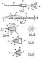
- a protective device 10 or housing here permanently associated with a short catheter The casing can also be manufactured as a semi-finished product adaptable in particular to a short commercial catheter in place of the traditional protective cover of it, that this element is manufactured by the original manufacturer to be assembled then to its short catheter or its injection devices equipped with a needle of original equipment, or that this element is manufactured by an equipment manufacturer who adapts to the original original products of its customers or suppliers manufacturers.
- the casing 10 is a one-piece piece of transparent thermo-flexible plastic material intended to be an integral part of the medical injection devices, whether it be short catheter, traditional syringes, including pre-filled syringes equipped with an original needle or any other IV series injection device, in particular a container device according to the invention as will be described later.
- the design of the housing 10 is such that, firstly, the intrusive side of the article for which it is intended, namely the sharp bevel of a needle, it ensures the protection of the cutting edge of the bevel, under any circumstances, against mechanical aggression bevel before first use. Secondly, after single use of the device, the casing, in permanent rest position, hides the aggressiveness of the bevel passively to avoid any injury, scratching or accidental sting due to the stained tip of the needle. Third, in its downstream design of the medical instrument for which it is intended, the housing has means for attachment to the body of the instrument, for example the pump body of a commercial syringe or the body of any another medical injection device, including commercial short catheters, thus ensuring its wider adaptability to all ranges of standard IV devices. It is a product concept with a maximum of degrees of freedom to promote the safety of hospital injections, vaccination campaigns and self-injections outside the clinic.
- the needle housing 10 has a general shape inspired by the shape of a Manta line whose fins 12, 12 have a rounded ends.
- the front portion 16 of the safety device is a shield that comes to marry and circumscribe the aggressiveness of the bevel 25 of the needle 24 without rubbing it, thanks to the forces internal elastics of the body 11 of the part acting as a housing, this body being secured to two functional elements, namely the front portion 16 or shield "and a base 14, all constituting a one-piece piece made by injection.
- the material used for this part 10 is for example a translucent silicone, such as that used for the manufacture of suction cups or nipples for bottles.
- the dimensions of the housing 10 are adapted to the distance between the shield and the base of the cannula.
- the protective shield 16 mechanically marries the bevel 25. It will be mentioned here that according to clinical studies and field tests conducted in recent years in the United States, the character of automatic protection and independent of the will of the operator is the best appreciated to meet the needs of security without modifying the professional gestures.
- this protection device is used with simple gestures, performed by the single dominant hand of the operator, safely during the surgical procedure, without the need for the cooperation of both hands to complete the whole act.
- This safety device exploits exclusively the physical properties of the plastic material of the housing 10: symmetrically reversing the fins 12 from horizontal to vertical inflects the curvature of said casing which passes from a concave shape to a convex shape with crossing of a state of instability.
- the mechanical characteristic is based on the elasticity of the part 10. These forces are dormant when the part 10 is at rest, like a concave lens. These forces of constraint come into action under the impulse printed by the natural gesture of the operator when he seizes the instrument.
- the cannula is then completely disengaged, ready to incise the skin and to penetrate according to the angle imparted by it. operator.
- the handling is very precise and the hands of the operator are, thanks to the housing 10, out of the field of action of the tip of the needle. Visibility is excellent too.
- the shield-base connection for a safety cover intended to equip, as an intrusive part, a short commercially available catheter such as a standard hypodermic needle of 23 ⁇ 1 caliber will be described in a concrete example, which corresponds to a cannula of useful length 25 mm and diameter 0.60 mm.
- the safety casing 10 cooperates at its base 14 with the female Luer cone 22 of the short catheter 20.
- an adaptation of the base of the safety device for example to the pump body of a traditional syringe is performed to meet certain normative constraints such as the transparency and mandatory readability of the graduation on said pump body.
- the housing 10 is formed of a single piece of plastic material such as a transparent silicone, whose geometric shape is for example, at least approximately, generated by the equation of a hyperbolic spiral.
- the housing thus has the general appearance of a thin and flexible lens, whose length is slightly greater than the total length of the needle 20 (canula + cone Luer) with which the housing 10 must cooperate, and its greater width is equal to about three quarters of its length. Its surface is smooth and slip-resistant.
- the thickness of the housing can be constant or variable depending on the density of the material used.
- the casing has its two lateral regions 12 forming fins, the ends of which are thinned to the limit of the functional convexity perimeter of the flexible lens. This arrangement, detailed below, is more particularly a variant of delivery position complies with the constraints of sterile packaging of the finished product. Another of the properties of the form is to facilitate fixation on the patient's skin at the level of the patient. device 10 to optimize stability in the case of permanent fixation.
- the casing 10 has at its geometric center a thickness which is twice the thickness at its outer edges 12.
- the variation in thickness can be constant or in steps.
- the shape of the piece relative to the horizontal plane is concave, so that the cannula 24 is arranged in the horizontal plane of the concave shape as the string of an arc, at the intersection of this horizontal plane with the vertical plane defined by the cannula.
- the monobloc housing 10 is naturally braced on the cannula, without constraint on the side of the bevel but with a firm anchoring on the cone Luer by its base 14.
- the top of the drooping arch is approximately at the intersection of the middle perpendicular of the cannula with a virtual line drawn on the vertical plane defined by the cannula.
- This virtual line forms an angle for example of 30 ° with the axis of the cannula, a value which determines the length L of the segment which connects the top of the housing in the rest position at the midpoint of the cannula.
- the top point of the housing 10 may, by design, be located upstream or downstream of the midpoint of the cannula without modifying the functionality of the part. On the contrary, the position of this point becomes a design parameter to optimize the shape of the part according to different constraints.
- a simple pressure of the index of the operator on the top of the housing causes a lever effect on the shield 16, which by straightening releases the tip 25 of the needle 24.
- Concomitantly the fins of the housing is raise spontaneously symmetrically, following the inversion of the curvature of the housing, thus offering a firm grip to the thumb and forefinger of the dominant hand of the operator.
- the base 14 which provides the securing function of the safety device 10 is a notch or light formed in the body of the part 10 and formed for example by two parallel incisions 141, 142 in the form of a blade through which passes through in all the thickness of the material of the housing, so as to clear a strip of material.
- the strap shape is that of a rectangular parallelepiped, constituting a flange that comes to tighten elastically on the luer cone 22 of the needle.
- the upstream blade stroke 141 is positioned at a small distance (typically 1 mm) from the outer edge of the housing 10 opposite the bevel 25.
- the downstream blade stroke 142 is positioned at, for example, 3 mm from the upstream blade stroke 141.
- the two parallel blade lines form an angle of 90 ° with the major axis of the housing 10, so as to provide a passage to the body of the luer cone while leaving the flange 14 completely integral with the casing by the short sides of the rectangular parallelepiped.
- the length of each blade stroke is close to the outer diameter of the Luer cone 22, measured at the right conical section located at the blade line considered.
- the inner surface of the strap or flange 14, in contact with the material to which it is anchored, in this case the outer surface of the luer cone, is a surface having, if appropriate, physical characteristics which increase the force of adhesion between the two parts under the sole pressure of the elasticity of the material put in tension.
- the casing 10 is thus secured to the luer cone while the casing caps the entire needle 24.
- the protective shield 16 bevel 25 it is formed of three elements integral with the material of the housing. These three elements are arranged so that the tip of the needle can not pierce the shield or avoid it.
- the first element is a frontal dike of material 161 in the axis of the tip of the cannula.
- the dimensions of this part are sufficient to oppose a serious resistance to the aggressiveness of the tip of the cannula.
- the two other elements 162 arranged symmetrically on either side of the axis of the cannula form an open channel whose edges are constituted by two prominences of half-moon shaped material to form a V-shaped beak, with the height V slightly greater than the length of the bevel 25 of the cannula.
- the internal spacing of the prominences of material, at the base of the V is here about 1.2 mm is a spacing sufficient for to accommodate without friction the maximum diameter of silicone cannula, which diameter does not exceed here 1.1 mm.
- the V is formed by the two material prominences 162 on the inner face of the housing, so that the tip of the V is substantially in alignment with the axis of the cannula 24 at a distance of about 1mm upstream of the bevel and a distance of about 1mm + the length of the bevel 25 + thickness of the dam 161 of the extreme edge of the housing.
- the function of the V-shaped spout is to wedge the cannula to prevent the material of the housing, always more abrasive than the soft steel, to undergo movements likely to blunt the bevel by friction, material against material, during the transport of the devices. injection devices equipped with the safety device.
- the shield 16 may be reinforced by a particularly metal deposit to increase its resistance to aggression of the tip of the cannula.
- the deposit is preferably secured to a guard (not shown) from the beak of the shield 16 to the top of the housing 10 in the protective position to oppose a bending resistance in the event of a frontal impact.
- this resistance can be provided by a rib injected into the material of the housing 10.
- this pre-filled compression element is provided with a cap or cap in the form of a circular flexible membrane crimped by a suitable method at the downstream end of the male luer cone. this element.
- the diameter of the circular membrane, the center of which is coaxial with the two coupled devices, is approximately 0.8 mm larger than the outer diameter of the end of the male Luer cone and 0.2 mm smaller than the inside diameter of the Luer cone.
- female 22 of the needle The coupling causes a tension of the membrane and reinforces the Morse wedging of the male and female organs.
- the penetration is limited by the wedging forces to about 4 or 5 mm.
- Halfway the tensioned membrane is exposed to a striker disposed within the female Luer cone coaxially with the two devices. This striker is in fact the end 27 of the cannula opposite its invasive tip, which is preferably short beveled.
- the cannula 24 is crimped to the female Luer cone 22 so that downstream of the crimping or gluing to the end of the intrusive bevel 25, its useful length corresponds to the standard.
- a safety device as described above makes it possible to coexist traditional injection devices with new ones. injection devices based on needle penetration.
- the other part of the injection device forming element of contention and expulsion of the therapeutic substance to be delivered, is based on a principle of single-dose individual cartridge pre-filled disposable.
- this element is destroyed after a single, unique and first use, some practices at the edge of vaccine safety will tend to disappear. To accelerate the eradication of these practices or at least contribute to it, it is essential that the cost of manufacturing such an element be as low as possible, and in particular less than or equal to the cost of using a traditional instrument. This equation is certainly not realistic in the case of programmed systematic re-use, but arbitration becomes even more favorable in economies of scarcity.
- conditioning functions namely the shape and mechanical characteristics of the container element and, later, some logistical aspects that relate to the capabilities of the injection device object of the invention to meet the dispensing functions such as sterility, availability in the emergency and the cold chain.
- the container element is thus a pre-filled, single-dose injectable cartridge whose downstream end consists of a male luer cone designed to fit the female luer cone of the specific short catheter 20 as described above, this cartridge being sealed by a thin and flexible membrane.
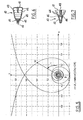
- the geometric shape of the peripheral turns of this element is advantageously generated by the polar coordinate equation of a logarithmic spiral, parameterized so that the volume of the container is preferably equal to the dose prescribed for the vaccine injections, for example 0 , 5 ml, 1 ml or 1.5 ml.
- hydrodynamic properties of such a container are such that, inside, a pressurized liquid is evacuated along the turns with a vortex effect.
- the dosage form of the injectable substance and its liquid excipient by adding, for example, a polymer which increases the viscosity of the injectable liquid. to the point of turning it into a gel.
- a polymer which increases the viscosity of the injectable liquid to the point of turning it into a gel.
- the hydrophilic and hydrophobic properties of the gel can also be used in certain therapeutic applications.
- the container preferably by a cold plasma technique, with an amorphous carbon layer, this being particularly suitable if the container is manufactured on the basis of polyethylene terephthalate (PET) or crystal polycarbonate, whose mechanical properties of crush resistance allow a smooth deformation under the pressure of the operator's thumb along the orthogonal axis of the device induced by the logarithmic spiral shape.
- PET polyethylene terephthalate
- crystal polycarbonate whose mechanical properties of crush resistance allow a smooth deformation under the pressure of the operator's thumb along the orthogonal axis of the device induced by the logarithmic spiral shape.
- the programmed deformation of the constituent material of the container subjected to the pressure of the thumb of the operator takes place between two stable positions of the injection device, namely the position illustrated on 4A where the turns are expanded by the stress of the matter that the shape of the mold imprints on the impression during the injection, and the position of the figure 4D where the turns are crushed due to the deformation of the material by the vertical pressure of the thumb of the operator.
- the stability of the second position depends on the thickness of the walls of the container, this thickness being calculated so that the resilience of the material does not cause a return movement likely to generate a post-operative aspiration.
- the container 40 is designed so that at constant pressure of the thumb of the operator on the rear base 41, the progressive crushing of the turns is substantially linear, with a steady flow and preferably substantially constant.
- two fins 46 arranged symmetrically in the outlet region of the container, in the dead space between the male Luer cone 42 and the base of the container, have the function of facilitating the catch of the instrument between the index finger and the middle finger of the dominant hand of the operator, so that the base of the container undergoes without sliding under the thumb pressure adequate and adapted to the resistance of the injection, and that this pressure exerted in the axis of the device is well distributed over the entire surface of the base 41.
- the funnel effect of the conical shape of the container 40 induces another fluid dynamics according to a different mathematical model. Specifically, reducing friction and increasing the viscosity of the injectable reduces turbulence as the container cavity is fully filled during automatic packaging.
- the injectable substance is in gel form at its maximum viscosity, and that the injectable dose sits inside the male Luer cone of the 42 of the container.
- This concentrated dose for example the size of a grain of wheat, is intended to be propelled by a lug 43 integral with the container, and which closely follows the cavity containing this dose.
- the lug 43 is an integral part of the base and is positioned in the axis of the device.
- the pressure of the thumb of the operator evacuates the air contained in the device 40 by lateral vents 45 arranged at the base of the device so that the volume of air evacuated under pressure opposes little or no resistance. Consequently, only the resistance to deformation of material opposes the pressure of the thumb of the operator and the propulsion of the injectable substance is under the mechanical pressure of the pin 43.
- the pin 43 can be dimensioned to stay stuck in the expulsion duct after injection, to ensure the unique use.
- FIG. 7 Another variant of the container, designed to perform a sample of body fluid, is shown on the figure 7 drawings. It is distinguished by the mechanical characteristics of the material, namely a thermo-flexible medical plastic material.
- the container here again comprises a lug 43, but which here has the function of closing, in compressed position, the male luer cone, so as to maintain the inner chamber of the container 40 in compression during the coupling of the needle 20 on the container before the procedure.
- This lug 43 is designed such that the sealing of the device is ensured and prevent outside air is likely to enter through the cannula during the coupling operation.
- This container 40 for the punctures of body fluids is thus delivered in the compression position. The maintenance of this stable position is guaranteed by a sealing cap which advantageously replaces the membrane forming a lid described above.
- This deposit preferably made by surface treatment, increases the seal to peripheral gas exchange. It is also supposed to increase the heat conduction deficit compared to glass, but such a property can become quite advantageous in the cases of non-respect of the cold chain, until bearing to the accidental or programmed breaks of this chain of the particularly in areas of the world where dispensary equipment is poor.
- an amorphous carbon internal coating has other advantages: first, its rigidity gives a better resistance to crushing the container, which reduces the risk of accidental discharge; in addition, the deformation of the container made for the injection causes a loss of integrity (rupture) of this amorphous carbon coating, and guarantees the single-use functionality by making the container unusable a second time.
- the casing 10 it is possible for the casing 10 to be made of a sufficiently malleable material so that at its outer edges it can be wound around the cannula 20 and to wrap the latter before the together be packaged for marketing, for example in blister packs. This arrangement makes it possible not to substantially modify the existing automatic blistering processes.
- the entire injection device for the exception of the needle
- the container and the protective device in one piece, for example silicone. This is applicable especially when the shelf life of the product to be injected is not critical.
Landscapes
- Health & Medical Sciences (AREA)
- Engineering & Computer Science (AREA)
- Animal Behavior & Ethology (AREA)
- General Health & Medical Sciences (AREA)
- Biomedical Technology (AREA)
- Heart & Thoracic Surgery (AREA)
- Hematology (AREA)
- Life Sciences & Earth Sciences (AREA)
- Vascular Medicine (AREA)
- Anesthesiology (AREA)
- Public Health (AREA)
- Veterinary Medicine (AREA)
- Environmental & Geological Engineering (AREA)
- Infusion, Injection, And Reservoir Apparatuses (AREA)
- Measurement Of The Respiration, Hearing Ability, Form, And Blood Characteristics Of Living Organisms (AREA)
- Electronic Switches (AREA)
Claims (11)
- Vorrichtung zum Enthalten eines Fluids, die geeignet ist, mit einem invasiven Element zusammenzuwirken, so wie einer Nadel, insbesondere zum injizieren einer therapeutischen Flüssigkeit oder zum Entnehmen einer Körperflüssigkeit, dadurch gekennzeichnet, dass sie einen Befestigungsteil (42) für das invasive Element, das eine allgemeine Achse der Vorrichtung definiert, und eine einstückige Hülle (40) umfasst, die im Wesentlichen entlang der Achse verformbar ist, wobei die Hülle eine konische Form aufweist und eine helixförmige Umfangsrippe (44) umfasst, die die bevorzugte Verformbarkeit entlang der allgemeinen Achse gewährleistet.
- Vorrichtung nach Anspruch 1, dadurch gekennzeichnet, dass die Trajektorie der Rippe (44) in einer Projektion in eine Ebene, die etwa rechtwinklig zu der allgemeinen Achse ist, der Gleichung einer logarithmischen Spirale entspricht.
- Vorrichtung nach einem der Ansprüche 1 oder 2, dadurch gekennzeichnet, dass der Befestigungsteil (42) und die Hülle (40) einstückig ausgeführt sind.
- Vorrichtung nach einem der Ansprüche 1 bis 3, dadurch gekennzeichnet, dass die Hülle (40) innen mit amorphem Kohlenstoff beschichtet ist.
- Vorrichtung nach einem der Ansprüche 1 bis 4, dadurch gekennzeichnet, dass sie in dem Befestigungsteil eine Flüssigkeitsausgangsöffnung umfasst, die mit einem Deckel versehen ist, der geeignet ist, durch eine innere Spitze einer Kanüle durchstochen oder verdrängt zu werden, die auf die Vorrichtung aufgesteckt ist.
- Vorrichtung nach einem der Ansprüche 1 bis 5, dadurch gekennzeichnet, dass sie außerdem einen Austreibungsvorsprung (43) umfasst, der in Höhe einer Seite (41) der Hülle, die dem Befestigungsteil gegenüberliegt, und um in diese einzudringen, um ein Fluid auszustoßen, vorgesehen ist.
- Vorrichtung nach Anspruch 6, dadurch gekennzeichnet, dass das Fluid ein viskoses Gel ist.
- Injektionsvorrichtung, dadurch gekennzeichnet, dass sie eine Behältervorrichtung nach einem der Ansprüche 1 bis 7 und ein invasives Element, so wie eine Nadel, und auch eine Schutzvorrichtung umfasst, die auf dem invasiven Element befestigt ist.
- Vorrichtung nach Anspruch 8, dadurch gekennzeichnet, dass das invasive Element und die Behältervorrichtung aus Kegeln gemäß Luerstandard zusammengesetzt sind.
- Vorrichtung nach Anspruch 8, dadurch gekennzeichnet, dass die Behältervorrichtung und die Schutzvorrichtung einstückig ausgerührt sind.
- Vorrichtung nach Anspruch 10, dadurch gekennzeichnet, dass die Behältervorrichtung und die Schutzvorrichtung aus Silikon ausgeführt sind.
Applications Claiming Priority (3)
| Application Number | Priority Date | Filing Date | Title |
|---|---|---|---|
| FR0209201A FR2842429A1 (fr) | 2002-07-19 | 2002-07-19 | Dispositif de protection pour un element invasif du type aiguille |
| FR0209201 | 2002-07-19 | ||
| PCT/FR2003/002300 WO2004009149A2 (fr) | 2002-07-19 | 2003-07-21 | Dispositif de protection pour un element invasif du type aiguille |
Publications (2)
| Publication Number | Publication Date |
|---|---|
| EP1525016A2 EP1525016A2 (de) | 2005-04-27 |
| EP1525016B1 true EP1525016B1 (de) | 2011-11-16 |
Family
ID=29797583
Family Applications (1)
| Application Number | Title | Priority Date | Filing Date |
|---|---|---|---|
| EP03753659A Expired - Lifetime EP1525016B1 (de) | 2002-07-19 | 2003-07-21 | Schutzvorrichtung für ein invasives element in form einer nadel |
Country Status (5)
| Country | Link |
|---|---|
| EP (1) | EP1525016B1 (de) |
| AT (1) | ATE533525T1 (de) |
| AU (1) | AU2003271822A1 (de) |
| FR (1) | FR2842429A1 (de) |
| WO (1) | WO2004009149A2 (de) |
Cited By (2)
| Publication number | Priority date | Publication date | Assignee | Title |
|---|---|---|---|---|
| EP2829296A1 (de) | 2013-07-24 | 2015-01-28 | Raumedic Ag | Medizinische Injektionsvorrichtung |
| EP2829295A1 (de) | 2013-07-24 | 2015-01-28 | Raumedic Ag | Medizinische Injektionsvorrichtung |
Families Citing this family (1)
| Publication number | Priority date | Publication date | Assignee | Title |
|---|---|---|---|---|
| FR2906476B1 (fr) * | 2006-09-30 | 2009-12-18 | Biofront | Dispositif d'injection a aiguille, pourvu d'un dispositif de condamnation automatique d'aiguille. |
Family Cites Families (9)
| Publication number | Priority date | Publication date | Assignee | Title |
|---|---|---|---|---|
| NL92087C (de) * | 1954-09-03 | |||
| US2911972A (en) * | 1954-09-14 | 1959-11-10 | Elinger Adolfo Scholcoff | Hypodermic syringe-ampulla |
| NL286398A (de) * | 1961-12-08 | 1900-01-01 | ||
| US4994046A (en) * | 1988-12-30 | 1991-02-19 | Vann T. Wesson | Needle guard for syringe |
| US5019048A (en) * | 1990-01-10 | 1991-05-28 | Margolin George D | Unit dose syringe with rotatable needle |
| DE4223689C2 (de) * | 1991-07-18 | 1994-08-25 | Daniel Panzer | Vorrichtung zur Injektion einer fertig vorbereiteten und abgemessene Flüssigkeit, insbesondere Phiolen- und Ampullenspritze |
| IT1257503B (it) * | 1992-09-24 | 1996-01-25 | Cgm Spa | Dispositivo porta-ago per penetrazione nel corpo, quale ago per fleboclisi, per dialisi e usi simili. |
| FR2779655B1 (fr) * | 1998-06-11 | 2000-09-01 | Vygon | Protecteur d'aiguille hypodermique |
| JP2002191695A (ja) * | 2000-10-20 | 2002-07-09 | Mitsubishi Pencil Co Ltd | 針先カバー部材、針先カバー部材付き注射針の組立方法、針ガード部材付き注射針および針ガード部材付き注射器 |
-
2002
- 2002-07-19 FR FR0209201A patent/FR2842429A1/fr active Pending
-
2003
- 2003-07-21 AT AT03753659T patent/ATE533525T1/de active
- 2003-07-21 EP EP03753659A patent/EP1525016B1/de not_active Expired - Lifetime
- 2003-07-21 WO PCT/FR2003/002300 patent/WO2004009149A2/fr not_active Ceased
- 2003-07-21 AU AU2003271822A patent/AU2003271822A1/en not_active Abandoned
Cited By (5)
| Publication number | Priority date | Publication date | Assignee | Title |
|---|---|---|---|---|
| EP2829296A1 (de) | 2013-07-24 | 2015-01-28 | Raumedic Ag | Medizinische Injektionsvorrichtung |
| EP2829295A1 (de) | 2013-07-24 | 2015-01-28 | Raumedic Ag | Medizinische Injektionsvorrichtung |
| DE102013214442A1 (de) | 2013-07-24 | 2015-01-29 | Raumedic Ag | Medizinische Injektionsvorrichtung |
| DE102013214429A1 (de) | 2013-07-24 | 2015-02-19 | Raumedic Ag | Medizinische Injektionsvorrichtung |
| US10279122B2 (en) | 2013-07-24 | 2019-05-07 | Raumedic Ag | Medical injection device |
Also Published As
| Publication number | Publication date |
|---|---|
| FR2842429A1 (fr) | 2004-01-23 |
| WO2004009149A9 (fr) | 2004-04-22 |
| AU2003271822A1 (en) | 2004-02-09 |
| ATE533525T1 (de) | 2011-12-15 |
| AU2003271822A8 (en) | 2004-02-09 |
| EP1525016A2 (de) | 2005-04-27 |
| WO2004009149A3 (fr) | 2004-08-26 |
| WO2004009149A2 (fr) | 2004-01-29 |
Similar Documents
| Publication | Publication Date | Title |
|---|---|---|
| EP1589926B2 (de) | Vorrichtung und verfahren zur extemporierten präparation einer sterilen flüssigen dosis | |
| EP0693949B1 (de) | Injektionsmodul für eine spritze | |
| FR2905273A1 (fr) | Dispositif d'injection automatique avec moyen de temporisation. | |
| FR2913200A1 (fr) | Dispositif de protection d'aiguille | |
| CA2956057C (fr) | Dispositif pour l'introduction d'une canule a bout arrondi sous la peau d'un patient | |
| JP2008504928A (ja) | 使い捨て注射器 | |
| EP3374007B1 (de) | Spritze | |
| EP1009301A1 (de) | Schutzvorrichtung für schneid- und/oder perfirierungswerkzeug | |
| EP3697478B1 (de) | Manuelle injektionsvorrichtung | |
| WO1989000432A2 (fr) | Seringue de haute securite non reutilisable | |
| EP1525016B1 (de) | Schutzvorrichtung für ein invasives element in form einer nadel | |
| EP3658064A1 (de) | Dentalspender | |
| WO2013072421A1 (fr) | Dispositif d'interfaçage d'un instrument d'injection de fluide et d'un flacon à perforer et procédé d'utilisation associé | |
| EP1545666B1 (de) | Nadel zum medizinischen gebrauch mit schutz gegen unbeabsichtigte nadelstiche | |
| EP3551253B1 (de) | Mehrfachdosisspender | |
| US20190125973A1 (en) | Combination needleless hypodermic injector and cover sheet and related methods | |
| FR2744437A1 (fr) | Dispositif et ensemble pour ouvrir des ampoules | |
| WO2008043895A2 (fr) | Dispositif d'injection a aiguille, pourvu d'un dispositif de condamnation automatique d'aiguille | |
| FR2648352A1 (fr) | Perfectionnement aux appareils d'injection sans aiguille a doses contenues dans des cartouches et cartouches a utiliser dans un tel appareil | |
| FR3154011A1 (fr) | Dispositif pour l’introduction d’une canule à bout arrondi sous la peau d’un patient | |
| CA2115240A1 (fr) | Dispositif de securite permettant la retraction par aspiration de l'aiguille a l'interieur du corps d'une seringe apres usage | |
| MC1510A1 (fr) | Seringue a cartouche avec aiguille incorporee | |
| WO2018002535A1 (fr) | Dispositif d'administration d'au moins un principe actif par voie per-muqueuse buccale | |
| FR2991574A1 (fr) | Embout de prehension interchangeable pour manipuler, poser ou extraire des lentilles corneennes |
Legal Events
| Date | Code | Title | Description |
|---|---|---|---|
| PUAI | Public reference made under article 153(3) epc to a published international application that has entered the european phase |
Free format text: ORIGINAL CODE: 0009012 |
|
| 17P | Request for examination filed |
Effective date: 20050221 |
|
| AK | Designated contracting states |
Kind code of ref document: A2 Designated state(s): AT BE BG CH CY CZ DE DK EE ES FI FR GB GR HU IE IT LI LU MC NL PT RO SE SI SK TR |
|
| AX | Request for extension of the european patent |
Extension state: AL LT LV MK |
|
| DAX | Request for extension of the european patent (deleted) | ||
| 17Q | First examination report despatched |
Effective date: 20071106 |
|
| GRAP | Despatch of communication of intention to grant a patent |
Free format text: ORIGINAL CODE: EPIDOSNIGR1 |
|
| GRAS | Grant fee paid |
Free format text: ORIGINAL CODE: EPIDOSNIGR3 |
|
| GRAA | (expected) grant |
Free format text: ORIGINAL CODE: 0009210 |
|
| AK | Designated contracting states |
Kind code of ref document: B1 Designated state(s): AT BE BG CH CY CZ DE DK EE ES FI FR GB GR HU IE IT LI LU MC NL PT RO SE SI SK TR |
|
| REG | Reference to a national code |
Ref country code: GB Ref legal event code: FG4D Free format text: NOT ENGLISH |
|
| REG | Reference to a national code |
Ref country code: CH Ref legal event code: EP |
|
| REG | Reference to a national code |
Ref country code: IE Ref legal event code: FG4D Free format text: LANGUAGE OF EP DOCUMENT: FRENCH |
|
| REG | Reference to a national code |
Ref country code: DE Ref legal event code: R096 Ref document number: 60339142 Country of ref document: DE Effective date: 20120119 |
|
| REG | Reference to a national code |
Ref country code: NL Ref legal event code: VDEP Effective date: 20111116 |
|
| PG25 | Lapsed in a contracting state [announced via postgrant information from national office to epo] |
Ref country code: NL Free format text: LAPSE BECAUSE OF FAILURE TO SUBMIT A TRANSLATION OF THE DESCRIPTION OR TO PAY THE FEE WITHIN THE PRESCRIBED TIME-LIMIT Effective date: 20111116 Ref country code: SE Free format text: LAPSE BECAUSE OF FAILURE TO SUBMIT A TRANSLATION OF THE DESCRIPTION OR TO PAY THE FEE WITHIN THE PRESCRIBED TIME-LIMIT Effective date: 20111116 Ref country code: GR Free format text: LAPSE BECAUSE OF FAILURE TO SUBMIT A TRANSLATION OF THE DESCRIPTION OR TO PAY THE FEE WITHIN THE PRESCRIBED TIME-LIMIT Effective date: 20120217 Ref country code: SI Free format text: LAPSE BECAUSE OF FAILURE TO SUBMIT A TRANSLATION OF THE DESCRIPTION OR TO PAY THE FEE WITHIN THE PRESCRIBED TIME-LIMIT Effective date: 20111116 Ref country code: PT Free format text: LAPSE BECAUSE OF FAILURE TO SUBMIT A TRANSLATION OF THE DESCRIPTION OR TO PAY THE FEE WITHIN THE PRESCRIBED TIME-LIMIT Effective date: 20120316 |
|
| REG | Reference to a national code |
Ref country code: IE Ref legal event code: FD4D |
|
| PG25 | Lapsed in a contracting state [announced via postgrant information from national office to epo] |
Ref country code: CY Free format text: LAPSE BECAUSE OF FAILURE TO SUBMIT A TRANSLATION OF THE DESCRIPTION OR TO PAY THE FEE WITHIN THE PRESCRIBED TIME-LIMIT Effective date: 20111116 |
|
| PG25 | Lapsed in a contracting state [announced via postgrant information from national office to epo] |
Ref country code: IE Free format text: LAPSE BECAUSE OF FAILURE TO SUBMIT A TRANSLATION OF THE DESCRIPTION OR TO PAY THE FEE WITHIN THE PRESCRIBED TIME-LIMIT Effective date: 20111116 Ref country code: BG Free format text: LAPSE BECAUSE OF FAILURE TO SUBMIT A TRANSLATION OF THE DESCRIPTION OR TO PAY THE FEE WITHIN THE PRESCRIBED TIME-LIMIT Effective date: 20120216 Ref country code: EE Free format text: LAPSE BECAUSE OF FAILURE TO SUBMIT A TRANSLATION OF THE DESCRIPTION OR TO PAY THE FEE WITHIN THE PRESCRIBED TIME-LIMIT Effective date: 20111116 Ref country code: CZ Free format text: LAPSE BECAUSE OF FAILURE TO SUBMIT A TRANSLATION OF THE DESCRIPTION OR TO PAY THE FEE WITHIN THE PRESCRIBED TIME-LIMIT Effective date: 20111116 Ref country code: SK Free format text: LAPSE BECAUSE OF FAILURE TO SUBMIT A TRANSLATION OF THE DESCRIPTION OR TO PAY THE FEE WITHIN THE PRESCRIBED TIME-LIMIT Effective date: 20111116 Ref country code: DK Free format text: LAPSE BECAUSE OF FAILURE TO SUBMIT A TRANSLATION OF THE DESCRIPTION OR TO PAY THE FEE WITHIN THE PRESCRIBED TIME-LIMIT Effective date: 20111116 |
|
| PG25 | Lapsed in a contracting state [announced via postgrant information from national office to epo] |
Ref country code: RO Free format text: LAPSE BECAUSE OF FAILURE TO SUBMIT A TRANSLATION OF THE DESCRIPTION OR TO PAY THE FEE WITHIN THE PRESCRIBED TIME-LIMIT Effective date: 20111116 Ref country code: IT Free format text: LAPSE BECAUSE OF FAILURE TO SUBMIT A TRANSLATION OF THE DESCRIPTION OR TO PAY THE FEE WITHIN THE PRESCRIBED TIME-LIMIT Effective date: 20111116 |
|
| REG | Reference to a national code |
Ref country code: AT Ref legal event code: MK05 Ref document number: 533525 Country of ref document: AT Kind code of ref document: T Effective date: 20111116 |
|
| PLBE | No opposition filed within time limit |
Free format text: ORIGINAL CODE: 0009261 |
|
| STAA | Information on the status of an ep patent application or granted ep patent |
Free format text: STATUS: NO OPPOSITION FILED WITHIN TIME LIMIT |
|
| PGFP | Annual fee paid to national office [announced via postgrant information from national office to epo] |
Ref country code: LU Payment date: 20120803 Year of fee payment: 10 |
|
| 26N | No opposition filed |
Effective date: 20120817 |
|
| PGFP | Annual fee paid to national office [announced via postgrant information from national office to epo] |
Ref country code: MC Payment date: 20120801 Year of fee payment: 10 |
|
| REG | Reference to a national code |
Ref country code: DE Ref legal event code: R097 Ref document number: 60339142 Country of ref document: DE Effective date: 20120817 |
|
| PGFP | Annual fee paid to national office [announced via postgrant information from national office to epo] |
Ref country code: FR Payment date: 20120803 Year of fee payment: 10 |
|
| PG25 | Lapsed in a contracting state [announced via postgrant information from national office to epo] |
Ref country code: AT Free format text: LAPSE BECAUSE OF FAILURE TO SUBMIT A TRANSLATION OF THE DESCRIPTION OR TO PAY THE FEE WITHIN THE PRESCRIBED TIME-LIMIT Effective date: 20111116 |
|
| PG25 | Lapsed in a contracting state [announced via postgrant information from national office to epo] |
Ref country code: DE Free format text: LAPSE BECAUSE OF NON-PAYMENT OF DUE FEES Effective date: 20130201 Ref country code: ES Free format text: LAPSE BECAUSE OF FAILURE TO SUBMIT A TRANSLATION OF THE DESCRIPTION OR TO PAY THE FEE WITHIN THE PRESCRIBED TIME-LIMIT Effective date: 20120227 |
|
| PG25 | Lapsed in a contracting state [announced via postgrant information from national office to epo] |
Ref country code: FI Free format text: LAPSE BECAUSE OF FAILURE TO SUBMIT A TRANSLATION OF THE DESCRIPTION OR TO PAY THE FEE WITHIN THE PRESCRIBED TIME-LIMIT Effective date: 20111116 |
|
| REG | Reference to a national code |
Ref country code: DE Ref legal event code: R119 Ref document number: 60339142 Country of ref document: DE Effective date: 20130201 |
|
| PGFP | Annual fee paid to national office [announced via postgrant information from national office to epo] |
Ref country code: CH Payment date: 20130808 Year of fee payment: 11 |
|
| PGFP | Annual fee paid to national office [announced via postgrant information from national office to epo] |
Ref country code: GB Payment date: 20130808 Year of fee payment: 11 |
|
| PGFP | Annual fee paid to national office [announced via postgrant information from national office to epo] |
Ref country code: BE Payment date: 20130808 Year of fee payment: 11 |
|
| PG25 | Lapsed in a contracting state [announced via postgrant information from national office to epo] |
Ref country code: MC Free format text: LAPSE BECAUSE OF NON-PAYMENT OF DUE FEES Effective date: 20130731 |
|
| REG | Reference to a national code |
Ref country code: FR Ref legal event code: ST Effective date: 20140331 |
|
| PG25 | Lapsed in a contracting state [announced via postgrant information from national office to epo] |
Ref country code: TR Free format text: LAPSE BECAUSE OF FAILURE TO SUBMIT A TRANSLATION OF THE DESCRIPTION OR TO PAY THE FEE WITHIN THE PRESCRIBED TIME-LIMIT Effective date: 20111116 |
|
| PG25 | Lapsed in a contracting state [announced via postgrant information from national office to epo] |
Ref country code: FR Free format text: LAPSE BECAUSE OF NON-PAYMENT OF DUE FEES Effective date: 20130731 |
|
| PG25 | Lapsed in a contracting state [announced via postgrant information from national office to epo] |
Ref country code: HU Free format text: LAPSE BECAUSE OF FAILURE TO SUBMIT A TRANSLATION OF THE DESCRIPTION OR TO PAY THE FEE WITHIN THE PRESCRIBED TIME-LIMIT Effective date: 20030721 |
|
| REG | Reference to a national code |
Ref country code: CH Ref legal event code: PL |
|
| GBPC | Gb: european patent ceased through non-payment of renewal fee |
Effective date: 20140721 |
|
| PG25 | Lapsed in a contracting state [announced via postgrant information from national office to epo] |
Ref country code: LI Free format text: LAPSE BECAUSE OF NON-PAYMENT OF DUE FEES Effective date: 20140731 Ref country code: CH Free format text: LAPSE BECAUSE OF NON-PAYMENT OF DUE FEES Effective date: 20140731 |
|
| PG25 | Lapsed in a contracting state [announced via postgrant information from national office to epo] |
Ref country code: GB Free format text: LAPSE BECAUSE OF NON-PAYMENT OF DUE FEES Effective date: 20140721 |
|
| PG25 | Lapsed in a contracting state [announced via postgrant information from national office to epo] |
Ref country code: LU Free format text: LAPSE BECAUSE OF NON-PAYMENT OF DUE FEES Effective date: 20130721 |
|
| PG25 | Lapsed in a contracting state [announced via postgrant information from national office to epo] |
Ref country code: BE Free format text: LAPSE BECAUSE OF NON-PAYMENT OF DUE FEES Effective date: 20140731 |