EP0278424B1 - Grinding media charging device - Google Patents
Grinding media charging device Download PDFInfo
- Publication number
- EP0278424B1 EP0278424B1 EP88101691A EP88101691A EP0278424B1 EP 0278424 B1 EP0278424 B1 EP 0278424B1 EP 88101691 A EP88101691 A EP 88101691A EP 88101691 A EP88101691 A EP 88101691A EP 0278424 B1 EP0278424 B1 EP 0278424B1
- Authority
- EP
- European Patent Office
- Prior art keywords
- balls
- drum
- set forth
- chute
- grinding
- Prior art date
- Legal status (The legal status is an assumption and is not a legal conclusion. Google has not performed a legal analysis and makes no representation as to the accuracy of the status listed.)
- Expired - Lifetime
Links
- 238000000227 grinding Methods 0.000 title claims abstract description 57
- 239000003638 chemical reducing agent Substances 0.000 claims description 3
- XEEYBQQBJWHFJM-UHFFFAOYSA-N Iron Chemical compound [Fe] XEEYBQQBJWHFJM-UHFFFAOYSA-N 0.000 description 14
- 229910052742 iron Inorganic materials 0.000 description 7
- 229910052751 metal Inorganic materials 0.000 description 6
- 239000002184 metal Substances 0.000 description 6
- 239000002994 raw material Substances 0.000 description 6
- 230000000452 restraining effect Effects 0.000 description 5
- 230000008901 benefit Effects 0.000 description 4
- 239000000203 mixture Substances 0.000 description 4
- 229910000831 Steel Inorganic materials 0.000 description 3
- 230000009467 reduction Effects 0.000 description 3
- 239000010959 steel Substances 0.000 description 3
- 230000009471 action Effects 0.000 description 2
- 238000010276 construction Methods 0.000 description 2
- 239000012634 fragment Substances 0.000 description 2
- 239000000463 material Substances 0.000 description 2
- 230000002093 peripheral effect Effects 0.000 description 2
- 125000006850 spacer group Chemical group 0.000 description 2
- VYZAMTAEIAYCRO-UHFFFAOYSA-N Chromium Chemical compound [Cr] VYZAMTAEIAYCRO-UHFFFAOYSA-N 0.000 description 1
- RYGMFSIKBFXOCR-UHFFFAOYSA-N Copper Chemical compound [Cu] RYGMFSIKBFXOCR-UHFFFAOYSA-N 0.000 description 1
- 235000019738 Limestone Nutrition 0.000 description 1
- 229910019142 PO4 Inorganic materials 0.000 description 1
- 239000004568 cement Substances 0.000 description 1
- 229910052804 chromium Inorganic materials 0.000 description 1
- 239000011651 chromium Substances 0.000 description 1
- 239000003245 coal Substances 0.000 description 1
- 230000006835 compression Effects 0.000 description 1
- 238000007906 compression Methods 0.000 description 1
- 230000001276 controlling effect Effects 0.000 description 1
- 229910052802 copper Inorganic materials 0.000 description 1
- 239000010949 copper Substances 0.000 description 1
- 230000003247 decreasing effect Effects 0.000 description 1
- 230000008030 elimination Effects 0.000 description 1
- 238000003379 elimination reaction Methods 0.000 description 1
- SZVJSHCCFOBDDC-UHFFFAOYSA-N iron(II,III) oxide Inorganic materials O=[Fe]O[Fe]O[Fe]=O SZVJSHCCFOBDDC-UHFFFAOYSA-N 0.000 description 1
- 239000006028 limestone Substances 0.000 description 1
- 238000012423 maintenance Methods 0.000 description 1
- 238000004519 manufacturing process Methods 0.000 description 1
- 150000002739 metals Chemical class 0.000 description 1
- 238000000034 method Methods 0.000 description 1
- 238000012986 modification Methods 0.000 description 1
- 230000004048 modification Effects 0.000 description 1
- 239000010452 phosphate Substances 0.000 description 1
- NBIIXXVUZAFLBC-UHFFFAOYSA-K phosphate Chemical compound [O-]P([O-])([O-])=O NBIIXXVUZAFLBC-UHFFFAOYSA-K 0.000 description 1
- 230000008569 process Effects 0.000 description 1
- 238000010298 pulverizing process Methods 0.000 description 1
- 230000001105 regulatory effect Effects 0.000 description 1
- 229910001220 stainless steel Inorganic materials 0.000 description 1
- 239000010935 stainless steel Substances 0.000 description 1
Images

Classifications
-
- B—PERFORMING OPERATIONS; TRANSPORTING
- B02—CRUSHING, PULVERISING, OR DISINTEGRATING; PREPARATORY TREATMENT OF GRAIN FOR MILLING
- B02C—CRUSHING, PULVERISING, OR DISINTEGRATING IN GENERAL; MILLING GRAIN
- B02C17/00—Disintegrating by tumbling mills, i.e. mills having a container charged with the material to be disintegrated with or without special disintegrating members such as pebbles or balls
- B02C17/18—Details
- B02C17/20—Disintegrating members
- B02C17/205—Adding disintegrating members to the tumbling mill
Definitions
- This invention relates to an apparatus for feeding grinding balls into a ball mill of a type such as a generally horizontal, cylindrical drum for pulverizing raw material. More particularly, the invention relates to an apparatus for uniformly feeding a few balls at a time into a bail mill.
- the metal balls gradually wear away from the continual rubbing and impact between each other. New balls eventually must be fed into the ball mill. To operate at peak grinding efficiency, it is desirable to uniformly feed new balls into the ball mill at approximately the same rate as old balls wear out. Depending on the type balls used for grinding a specific raw material, the ball attrition rate can be accurately determined.
- Raw material is normally fed into ball mills at rates corresponding to the output of the pulverized material.
- the input rate of raw material is frequently controlled using such parameters relating to grinding efficiency as sound, power consumption, fineness of pulverized material, etc.
- Using the same parameters have been proposed in the prior art for controlling feed rates of grinding balls.
- devices for uniformly feeding a few balls at a time that can correspond to the ball attrition rate in a grinding mill are not known in the art.
- new balls may be systematically added to a grinding mill, they see generally added in batches of several hundred pounds at a time. This cyclical loading of the grinding mill greatly increases the power requirements to operate the grinding mill. More importantly, the grinding efficiency of the grinding mill is decreased. Peak grinding efficiency cannot be maintained if the ratio of balls to the ore to be pulverized is not uniformly maintained.
- U.S. Patent No. 3,542,300 discloses a large ball hopper for feeding balls into a ball mill.
- the hopper includes a number of compartments for holding balls. The balls are periodically released by rotating the entire hopper, including its complete charge of balls.
- SU-A- 216 428 discloses an apparatus for feeding grinding balls into a ball mill comprising the features of the preamble of claim 1, the regulator being a reciprocating cylinder.
- Our improved ball feeding apparatus overcomes the problems described above by controllably feeding balls from a ball storage hopper into a small rotating discharge drum having ball compartments.
- the drum is operated at a predetermined speed to uniformly feed a few balls at a time into a grinding mill.
- As a ball charge is emptied from each compartment the drum rotates an empty compartment into an an in-line relationship with the ball storage hopper for refilling with a new charge of balls.
- An advantage of our invention is that it is inexpensive to build and operate because of its compact size and maintenance free operation.
- a further advantage of our invention is the minimal energy required to operate it.
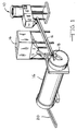
- reference numeral 10 denotes our ball feeding apparatus used in a grinding system.
- grinding balls 12 and raw ore 14 to be pulverized are fed into an entry end 18 of a generally horizontal, cylindrical grinding mill 16.
- Grinding mill 16 is normally rotated using an electric motor and conventional ring and pinion gearing (not shown).
- mill 16 rotates ore 14 is eventually pulverized by the cascading action of the tumbling balls and the pulverized ore exits mill 16 onto a conveyor 20.
- our device 10 uniformly adds grinding balls 12 to grinding mill 16 which can be controlled to substantially correspond to the attrition rate of the grinding balls in grinding mill 16.
- FIG. 2 shows an end view of feeding apparatus 10 mounted on legs 30.
- Feeding apparatus 10 includes a hopper 22 from which new grinding balls 12 are supplied, a regulator 25 for dispensing balls 12 to mill 16 through an outlet 28, and a chute 24 which conveys balls 12 from hopper 22 to regulator 25.
- Regulator 25 includes a discharge drum 26 mounted on a shaft 32 journalled in bearings 34 and rotated by an electric motor 40 through a drive chain 38. In the event drum 26 should ever become jammed, breakage of shaft 32 or chain 38 is prevented by incorporating a torque limiting device 36 as is well known.
- a conventional 1750 RPM, 1/4 HP DC motor 40 is quite satisfactory for operating drum 26.
- the speed of motor 40 is reduced by a conventional reducer 42 having a gear reduction ratio of 2500:1.
- the actual speed of drum 26 is set and monitored using a conventional speed controller 44.
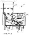
- FIG. 3 shows a sectional view of ball feeding apparatus 10 taken along line 3-3 in FIG. 2.
- Chute 24 includes a lower end 46 positioned adjacent drum 26 and an upper end 48 positioned adjacent to and below hopper 22 for receiving grinding balls 12.
- Chute 24 includes a grating 50 for allowing refuse such as metal fragments, ball fragments, dirt and the like to be removed through an outlet 52.
- a baffle such as metal panel 54 is hinged at 56 for regulating the depth of grinding balls 12 on chute 24. The depth of grinding balls 12 must be controlled so that a relatively thin layer 60 of balls 12 is metered into drum 26 via chute 24.
- chute 24 is inclined toward drum 26 to allow gravitational feeding of balls 12.
- chute 24 should have a slope of at least about 5°, preferrably at least 10° with 18° being most preferred. The lower slopes are less desirable because additional means such as vibrators may be required to cause flow of balls 12 through chute 24 to drum 26.
- Regulator 25 further includes a means for retaining the balls such as plate 62 having an upper end 64 and a lower end 66.
- Plate 62 is positioned adjacent to and below lower end 46 of chute 24 and maintained adjacent to a portion of the underside of drum 26 by a restraining means 68. Details as to the purpose and operation of plate 62 and restraining means 68 are provided later.
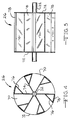
- FIGS. 4 and 5 provide details for the construction of drum 26.
- Drum 26 includes a plurality of compartments 70 whose lateral sides are formed by discs 72 mounted on shaft 32 and whose radial sides are formed by radially extending blades 74 mounted on shaft 32.
- Compartments 70 are evenly separated by facing plates 78.
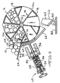
- FIG. 6 shows in detail construction of a preferred embodiment for plate 62.
- compartment 70a As compartment 70a is releasing its charge of balls 12 to grinding mill 16, compartment 70b is rotated into position to receive balls from chute 24. Balls roll into compartment 70b as the upper right hand portion of compartment 70b is being rotated past lower end 46 of chute 24. Plate 62 prevents balls 12 from falling from the lower left hand portion of compartment 70b until face 78 is rotated past end 46 of chute 24.
- Restraining means 68 includes a screw 84 for adjusting the compression, if necessary, of a spring 86. Screw 84 and spring 86 are contained inside a tube 88 which is welded to a body portion 92. A piston 96 is connected to a spacer 90 for compressing spring 86 with piston 96 extending through body portion 92. Piston 96 is biased into abutment with upper end 64 of plate 62 by spring 86. Restraining means 68 is anchored against movement by connecting (not shown) body portion 92 to a frame member of apparatus 10.
- feeding apparatus 10 is used to process ores such as iron ore (magnetite)
- the steel components of apparatus 10 may become magnetized. Iron scraps become more prone to sticking to drum 26 and plate 62.
- a variety of grinding ball sizes are used depending upon the ore to be pulverized. Balls as small as 25mm (1 inch) or smaller and up to about 127 mm (5 inches) may be used. Normally, a mixture of ball sizes will be used. A 50-25-25 mix comprising about 50% 51 mm (2 inch) balls, 25% 38 mm (1-1/2) balls and 25% 25mm (1 inch) balls is fairly common for iron ore grinding. For drum 26 shown in FIGS.
- Controller Setting Delivery Rate For 50-25-25 Grinding Balls 20% 68,1 Kg/h (150 lb/hr) 30% 113,5 Kg/h (250 lb/hr) 40% 143 Kg/h (315 lb/hr) 60% 227 Kg/h (500 lb/hr) 80% 326,9 Kg/h (720 lb/hr)
- the ball attrition rate was approximately 127,1 Kg/h (280 lb/hr).
- controller 44 would be set at approximately 35% to correspond to this feed rate. It was observed this setting caused the drum 26 to make one full revolution in about nine minutes. Therefore, one revolution of drum 26 would feed approximately 19,1 Kg (42 lb) of grinding balls to grinding mill 16.
- Each compartment 70 would correspond to 1/6 revolution or 3,18 Kg (7 lb) of grinding balls being fed about every 1-1/2 minutes.
- our compact drum 26 can uniformly feed a few grinding balls at a time into a grinding mill. Once the ball attrition rate has been determined, balls in a grinding mill can be replenished at a rate to substantially correspond to that attrition rate. Peak grinding efficiency can be insured since a constant ration of mass of balls to mass of ore to be pulverized is maintained. Furthermore, very little energy is required since the total mass of balls held by drum 26 is minimized.
Landscapes
- Engineering & Computer Science (AREA)
- Food Science & Technology (AREA)
- Crushing And Grinding (AREA)
- Disintegrating Or Milling (AREA)
- Grinding Of Cylindrical And Plane Surfaces (AREA)
- Constituent Portions Of Griding Lathes, Driving, Sensing And Control (AREA)
- Polarising Elements (AREA)
- Mechanical Treatment Of Semiconductor (AREA)
- Peptides Or Proteins (AREA)
- Medicines Containing Plant Substances (AREA)
- Medicines Containing Material From Animals Or Micro-Organisms (AREA)
Priority Applications (1)
| Application Number | Priority Date | Filing Date | Title |
|---|---|---|---|
| AT88101691T ATE83177T1 (de) | 1987-02-11 | 1988-02-05 | Zufuehrvorrichtung fuer mahlkoerper. |
Applications Claiming Priority (2)
| Application Number | Priority Date | Filing Date | Title |
|---|---|---|---|
| US07/017,295 US4715546A (en) | 1987-02-11 | 1987-02-11 | Grinding media charging device |
| US17295 | 1987-02-11 |
Publications (3)
| Publication Number | Publication Date |
|---|---|
| EP0278424A2 EP0278424A2 (en) | 1988-08-17 |
| EP0278424A3 EP0278424A3 (en) | 1989-09-06 |
| EP0278424B1 true EP0278424B1 (en) | 1992-12-09 |
Family
ID=21781810
Family Applications (1)
| Application Number | Title | Priority Date | Filing Date |
|---|---|---|---|
| EP88101691A Expired - Lifetime EP0278424B1 (en) | 1987-02-11 | 1988-02-05 | Grinding media charging device |
Country Status (10)
| Country | Link |
|---|---|
| US (1) | US4715546A (enExample) |
| EP (1) | EP0278424B1 (enExample) |
| AT (1) | ATE83177T1 (enExample) |
| AU (1) | AU593166B2 (enExample) |
| BR (1) | BR8800558A (enExample) |
| CA (1) | CA1294938C (enExample) |
| DE (1) | DE3876457T2 (enExample) |
| ES (1) | ES2036224T3 (enExample) |
| FI (1) | FI88266C (enExample) |
| GR (1) | GR3006851T3 (enExample) |
Families Citing this family (18)
| Publication number | Priority date | Publication date | Assignee | Title |
|---|---|---|---|---|
| US5224659A (en) * | 1992-02-21 | 1993-07-06 | Control International | Apparatus for feeding grinding balls |
| US5865385A (en) * | 1997-02-21 | 1999-02-02 | Arnett; Charles R. | Comminuting media comprising martensitic/austenitic steel containing retained work-transformable austenite |
| CN102026895B (zh) * | 2008-05-15 | 2014-08-13 | 氟石科技公司 | 可调节的输送机槽 |
| FI122276B (fi) * | 2010-04-12 | 2011-11-15 | Outotec Oyj | Laitteisto jauhinkappaleiden syöttämiseksi jauhatusmyllyyn |
| US9333507B2 (en) * | 2013-01-15 | 2016-05-10 | Knight Industrial Equipment Inc. | Automatic ball charging system for a ball mill assembly |
| CN103041898B (zh) * | 2013-01-16 | 2014-07-09 | 河北联合大学 | 球磨机自动加球配球机 |
| RU2540537C2 (ru) * | 2013-02-26 | 2015-02-10 | Богданов Лев Константинович | Способ и устройство для измельчения |
| CN103240159A (zh) * | 2013-05-24 | 2013-08-14 | 南通中正机械有限公司 | 新型锁风装置 |
| CN104668048B (zh) * | 2013-11-29 | 2017-10-27 | 中冶长天国际工程有限责任公司 | 一种自动加球机 |
| CN106513118A (zh) * | 2016-12-13 | 2017-03-22 | 西藏华泰龙矿业开发有限公司 | 一种钢球自动添加机 |
| CN106694111A (zh) * | 2016-12-13 | 2017-05-24 | 西藏华泰龙矿业开发有限公司 | 加球机 |
| CN106391222B (zh) * | 2016-12-20 | 2019-03-15 | 本钢板材股份有限公司 | 球磨机用凹槽式自动加球机 |
| CN107537639A (zh) * | 2017-08-25 | 2018-01-05 | 金川集团股份有限公司 | 一种用于球磨机的钢球自动添加控制装置 |
| BR102018009587A2 (pt) * | 2018-05-11 | 2019-11-26 | Metso Brasil Industria E Comércio Ltda. | Sistema de alimentação de corpos de cominuição em moinhos verticais |
| CN109225493B (zh) * | 2018-11-06 | 2020-06-23 | 福建亚亨机械股份有限公司 | 一种球磨设备加球装置抓球控制方法 |
| CN110586267B (zh) * | 2019-09-05 | 2020-12-18 | 沈冬 | 一种球磨机用磨球自动提升装填装置 |
| CN113210086B (zh) * | 2021-06-17 | 2022-12-02 | 长沙有色冶金设计研究院有限公司 | 一种球磨机加球设备及其应用方法 |
| CN117085799B (zh) * | 2023-08-03 | 2025-08-15 | 龙佰禄丰钛业有限公司 | 一种钛白粉生产中砂磨机锆珠在线添加装置 |
Family Cites Families (3)
| Publication number | Priority date | Publication date | Assignee | Title |
|---|---|---|---|---|
| GB1216191A (en) * | 1967-01-05 | 1970-12-16 | Foster Wheeler Brown Boilers | Improvements in and relating to pulverising mills |
| DE2242174A1 (de) * | 1972-08-26 | 1974-03-07 | Netzsch Maschinenfabrik | Verfahren und vorrichtung zum feinmahlen und dispergieren |
| DE3437299C2 (de) * | 1984-10-11 | 1993-11-04 | Babcock Energie Umwelt | Vorrichtung zum einfuellen von mahlkoerpern in eine rohrmuehle |
-
1987
- 1987-02-11 US US07/017,295 patent/US4715546A/en not_active Expired - Fee Related
-
1988
- 1988-01-19 CA CA000556864A patent/CA1294938C/en not_active Expired - Fee Related
- 1988-02-05 AT AT88101691T patent/ATE83177T1/de active
- 1988-02-05 EP EP88101691A patent/EP0278424B1/en not_active Expired - Lifetime
- 1988-02-05 DE DE8888101691T patent/DE3876457T2/de not_active Expired - Fee Related
- 1988-02-05 ES ES198888101691T patent/ES2036224T3/es not_active Expired - Lifetime
- 1988-02-09 FI FI880575A patent/FI88266C/fi not_active IP Right Cessation
- 1988-02-10 AU AU11495/88A patent/AU593166B2/en not_active Ceased
- 1988-02-10 BR BR8800558A patent/BR8800558A/pt not_active IP Right Cessation
-
1993
- 1993-01-21 GR GR930400102T patent/GR3006851T3/el unknown
Non-Patent Citations (1)
| Title |
|---|
| SOVIET INVENTIONS ILLUSTRATED, section III, January 1969, Mechanical & General; Derwent Publications Ltd., London * |
Also Published As
| Publication number | Publication date |
|---|---|
| CA1294938C (en) | 1992-01-28 |
| ATE83177T1 (de) | 1992-12-15 |
| FI880575A0 (fi) | 1988-02-09 |
| DE3876457T2 (de) | 1993-06-03 |
| FI88266C (fi) | 1993-04-26 |
| EP0278424A3 (en) | 1989-09-06 |
| AU593166B2 (en) | 1990-02-01 |
| EP0278424A2 (en) | 1988-08-17 |
| FI880575A7 (fi) | 1988-08-12 |
| US4715546A (en) | 1987-12-29 |
| FI88266B (fi) | 1993-01-15 |
| AU1149588A (en) | 1988-08-18 |
| DE3876457D1 (de) | 1993-01-21 |
| GR3006851T3 (enExample) | 1993-06-30 |
| BR8800558A (pt) | 1988-09-27 |
| ES2036224T3 (es) | 1993-05-16 |
Similar Documents
| Publication | Publication Date | Title |
|---|---|---|
| EP0278424B1 (en) | Grinding media charging device | |
| KR101917568B1 (ko) | 롤밀과 해머밀을 2단으로 배치한 파쇄기 | |
| JP5409634B2 (ja) | 鉱物性または非鉱物性材料の粉砕のための方法および装置 | |
| US4134556A (en) | Tire shredder | |
| RU2562836C2 (ru) | Способ и устройство для измельчения руды | |
| CN107499954A (zh) | 耐火材料生产系统 | |
| CN112337554A (zh) | 一种可自动进料式多级矿石粉碎装置 | |
| US2555171A (en) | Material reduction mill | |
| US3529778A (en) | Grinding method and system | |
| US4347986A (en) | Self-attritioning pulverizer | |
| CN117000372B (zh) | 一种具有料量调节机构的粉碎设备 | |
| CN107537639A (zh) | 一种用于球磨机的钢球自动添加控制装置 | |
| US4643365A (en) | Apparatus for adding grinding media to a grinding mill | |
| KR100899791B1 (ko) | 산화철 선별 및 분쇄장치 | |
| US3498548A (en) | Fluff mill | |
| US797616A (en) | Rotary breaker. | |
| KR100896632B1 (ko) | 분코크스 파쇄장치 | |
| RU2173217C2 (ru) | Двухроторная инерционная дробилка | |
| US4215825A (en) | Crusher with impacting bars | |
| CN223170993U (zh) | 一种球磨加球机挡漏球装置 | |
| JP2709666B2 (ja) | 竪型粉砕機 | |
| JP2518982B2 (ja) | 竪型ミルによる粉砕装置 | |
| CN219849794U (zh) | 一种农产品加工生产用研磨装置 | |
| SU1740061A1 (ru) | Измельчитель | |
| SU904576A1 (ru) | Молоткова дробилка дл приготовлени комбикормов |
Legal Events
| Date | Code | Title | Description |
|---|---|---|---|
| PUAI | Public reference made under article 153(3) epc to a published international application that has entered the european phase |
Free format text: ORIGINAL CODE: 0009012 |
|
| AK | Designated contracting states |
Kind code of ref document: A2 Designated state(s): AT BE CH DE ES FR GB GR IT LI NL SE |
|
| RAP1 | Party data changed (applicant data changed or rights of an application transferred) |
Owner name: THE HOLMING COMPANY Owner name: ARMCO INC. |
|
| PUAL | Search report despatched |
Free format text: ORIGINAL CODE: 0009013 |
|
| AK | Designated contracting states |
Kind code of ref document: A3 Designated state(s): AT BE CH DE ES FR GB GR IT LI NL SE |
|
| RHK1 | Main classification (correction) |
Ipc: B02C 17/18 |
|
| 17P | Request for examination filed |
Effective date: 19900221 |
|
| 17Q | First examination report despatched |
Effective date: 19910516 |
|
| ITF | It: translation for a ep patent filed | ||
| GRAA | (expected) grant |
Free format text: ORIGINAL CODE: 0009210 |
|
| AK | Designated contracting states |
Kind code of ref document: B1 Designated state(s): AT BE CH DE ES FR GB GR IT LI NL SE |
|
| REF | Corresponds to: |
Ref document number: 83177 Country of ref document: AT Date of ref document: 19921215 Kind code of ref document: T |
|
| REF | Corresponds to: |
Ref document number: 3876457 Country of ref document: DE Date of ref document: 19930121 |
|
| ET | Fr: translation filed | ||
| ITTA | It: last paid annual fee | ||
| REG | Reference to a national code |
Ref country code: GR Ref legal event code: FG4A Free format text: 3006851 |
|
| PLBE | No opposition filed within time limit |
Free format text: ORIGINAL CODE: 0009261 |
|
| STAA | Information on the status of an ep patent application or granted ep patent |
Free format text: STATUS: NO OPPOSITION FILED WITHIN TIME LIMIT |
|
| 26N | No opposition filed | ||
| PGFP | Annual fee paid to national office [announced via postgrant information from national office to epo] |
Ref country code: CH Payment date: 19950112 Year of fee payment: 8 |
|
| PGFP | Annual fee paid to national office [announced via postgrant information from national office to epo] |
Ref country code: FR Payment date: 19950113 Year of fee payment: 8 |
|
| PGFP | Annual fee paid to national office [announced via postgrant information from national office to epo] |
Ref country code: SE Payment date: 19950116 Year of fee payment: 8 Ref country code: AT Payment date: 19950116 Year of fee payment: 8 |
|
| PGFP | Annual fee paid to national office [announced via postgrant information from national office to epo] |
Ref country code: DE Payment date: 19950123 Year of fee payment: 8 |
|
| PGFP | Annual fee paid to national office [announced via postgrant information from national office to epo] |
Ref country code: BE Payment date: 19950125 Year of fee payment: 8 |
|
| PGFP | Annual fee paid to national office [announced via postgrant information from national office to epo] |
Ref country code: GB Payment date: 19950126 Year of fee payment: 8 |
|
| PGFP | Annual fee paid to national office [announced via postgrant information from national office to epo] |
Ref country code: GR Payment date: 19950127 Year of fee payment: 8 |
|
| EAL | Se: european patent in force in sweden |
Ref document number: 88101691.9 |
|
| PGFP | Annual fee paid to national office [announced via postgrant information from national office to epo] |
Ref country code: ES Payment date: 19950209 Year of fee payment: 8 |
|
| PGFP | Annual fee paid to national office [announced via postgrant information from national office to epo] |
Ref country code: NL Payment date: 19950228 Year of fee payment: 8 |
|
| REG | Reference to a national code |
Ref country code: ES Ref legal event code: PC2A Owner name: GS TECHNOLOGIES OPERATING CO., INC. (TITULAR DEL 5 |
|
| PG25 | Lapsed in a contracting state [announced via postgrant information from national office to epo] |
Ref country code: GB Effective date: 19960205 Ref country code: AT Effective date: 19960205 |
|
| PG25 | Lapsed in a contracting state [announced via postgrant information from national office to epo] |
Ref country code: SE Effective date: 19960206 Ref country code: ES Free format text: LAPSE BECAUSE OF NON-PAYMENT OF DUE FEES Effective date: 19960206 |
|
| PG25 | Lapsed in a contracting state [announced via postgrant information from national office to epo] |
Ref country code: BE Effective date: 19960228 |
|
| PG25 | Lapsed in a contracting state [announced via postgrant information from national office to epo] |
Ref country code: LI Effective date: 19960229 Ref country code: CH Effective date: 19960229 |
|
| REG | Reference to a national code |
Ref country code: CH Ref legal event code: PUEA Free format text: ARMCO INC.;THE HOLMING COMPANY TRANSFER- THE HOLMING COMPANY;GE TECHNOLOGIES OPERATING CO., INC. |
|
| BERE | Be: lapsed |
Owner name: THE HOLMING CY Effective date: 19960228 Owner name: ARMCO INC. Effective date: 19960228 |
|
| PG25 | Lapsed in a contracting state [announced via postgrant information from national office to epo] |
Ref country code: GR Free format text: THE PATENT HAS BEEN ANNULLED BY A DECISION OF A NATIONAL AUTHORITY Effective date: 19960831 |
|
| PG25 | Lapsed in a contracting state [announced via postgrant information from national office to epo] |
Ref country code: NL Effective date: 19960901 |
|
| GBPC | Gb: european patent ceased through non-payment of renewal fee |
Effective date: 19960205 |
|
| REG | Reference to a national code |
Ref country code: CH Ref legal event code: PL |
|
| PG25 | Lapsed in a contracting state [announced via postgrant information from national office to epo] |
Ref country code: FR Effective date: 19961031 |
|
| REG | Reference to a national code |
Ref country code: GR Ref legal event code: MM2A Free format text: 3006851 |
|
| NLV4 | Nl: lapsed or anulled due to non-payment of the annual fee |
Effective date: 19960901 |
|
| PG25 | Lapsed in a contracting state [announced via postgrant information from national office to epo] |
Ref country code: DE Effective date: 19961101 |
|
| REG | Reference to a national code |
Ref country code: FR Ref legal event code: ST |
|
| REG | Reference to a national code |
Ref country code: ES Ref legal event code: FD2A Effective date: 19990301 |
|
| PG25 | Lapsed in a contracting state [announced via postgrant information from national office to epo] |
Ref country code: IT Free format text: LAPSE BECAUSE OF NON-PAYMENT OF DUE FEES;WARNING: LAPSES OF ITALIAN PATENTS WITH EFFECTIVE DATE BEFORE 2007 MAY HAVE OCCURRED AT ANY TIME BEFORE 2007. THE CORRECT EFFECTIVE DATE MAY BE DIFFERENT FROM THE ONE RECORDED. Effective date: 20050205 |