EP0278088B1 - Radaufhängung - Google Patents
Radaufhängung Download PDFInfo
- Publication number
- EP0278088B1 EP0278088B1 EP87118474A EP87118474A EP0278088B1 EP 0278088 B1 EP0278088 B1 EP 0278088B1 EP 87118474 A EP87118474 A EP 87118474A EP 87118474 A EP87118474 A EP 87118474A EP 0278088 B1 EP0278088 B1 EP 0278088B1
- Authority
- EP
- European Patent Office
- Prior art keywords
- recess
- shock
- drive shaft
- shaft
- absorbing leg
- Prior art date
- Legal status (The legal status is an assumption and is not a legal conclusion. Google has not performed a legal analysis and makes no representation as to the accuracy of the status listed.)
- Expired - Lifetime
Links
Images


Classifications
-
- B—PERFORMING OPERATIONS; TRANSPORTING
- B60—VEHICLES IN GENERAL
- B60G—VEHICLE SUSPENSION ARRANGEMENTS
- B60G3/00—Resilient suspensions for a single wheel
- B60G3/18—Resilient suspensions for a single wheel with two or more pivoted arms, e.g. parallelogram
- B60G3/20—Resilient suspensions for a single wheel with two or more pivoted arms, e.g. parallelogram all arms being rigid
- B60G3/24—Resilient suspensions for a single wheel with two or more pivoted arms, e.g. parallelogram all arms being rigid a rigid arm being formed by the live axle
-
- B—PERFORMING OPERATIONS; TRANSPORTING
- B60—VEHICLES IN GENERAL
- B60G—VEHICLE SUSPENSION ARRANGEMENTS
- B60G15/00—Resilient suspensions characterised by arrangement, location or type of combined spring and vibration damper, e.g. telescopic type
- B60G15/02—Resilient suspensions characterised by arrangement, location or type of combined spring and vibration damper, e.g. telescopic type having mechanical spring
- B60G15/06—Resilient suspensions characterised by arrangement, location or type of combined spring and vibration damper, e.g. telescopic type having mechanical spring and fluid damper
- B60G15/062—Resilient suspensions characterised by arrangement, location or type of combined spring and vibration damper, e.g. telescopic type having mechanical spring and fluid damper the spring being arranged around the damper
Definitions
- the invention relates to a wheel suspension according to the preamble of claim 1.
- DE-OS 26 33 402 a generic wheel suspension with a shock absorber is known, which is provided in its cylindrical tube part with an indentation so that an axle drive shaft can pass freely near the shock absorber. Impressions in the cylindrical tube part of the damper are possible with two-tube dampers on the outer tube. On the other hand, such indentations in single-tube dampers can only be applied in a certain area due to the movable piston in the cylinder of the damper, and this attachment to the piston-guiding tube can only be carried out with considerable effort.
- DE-OS 33 42 355 describes a wheel suspension with a spring strut which has a connecting element facing a lower link.
- This is designed as a fork in such a way that an axle drive shaft can be passed through between two fork tines.
- the invention has for its object to provide a wheel suspension of the generic type in which an axle drive shaft is to be arranged unimpeded by a strut and installation and removal of the axle drive shaft is simplified.
- the main advantages achieved by the invention are that, due to the groove-shaped recess in the connecting element which is open towards the axle drive shaft, the shaft has a position within the circumferential contour of the element can take, the connecting element itself has no much larger diameter than the cylindrical part of the strut.
- the recess, which is open to the outside, enables simple and quick assembly of the axle drive shaft without the connecting element or the suspension strut having to be released from the lower link.
- the connecting element is preferably designed so that an end bearing part is arranged centrally to the cylindrical tube part of the shock absorber.
- the recess is so large that the movement of the axle drive shaft is not hindered during wheel movements and a sufficient distance is provided between this shaft and the recess. Since the wheel movement and the resulting handlebar movements are known, the contour of the recess can be designed according to the possible movements of the shaft, as is characterized in particular in claim 2.
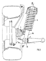
- a wheel suspension for a motor vehicle comprises a wishbone 1, which is arranged below an axle drive shaft 2 and on which a lower end 4 of a spring strut 5 is articulated via a joint 13 is.
- this lower end 4 consists of a connecting element 6 which at the end carries a joint or a bearing part 7 and is firmly connected at its opposite end 8 to the cylindrical part 9 of the spring strut 5.
- the connecting element 6 with respect to the vehicle — has a transverse groove-shaped recess 10 which is curved.
- the shaft 3 is arranged with play b so that it lies approximately within the outer contour 11 of the connecting element 6.
- the recess 10 extends with respect to the shaft 3 beyond the longitudinal center axis 12 of the strut 5, so that the shaft 3 is directly adjacent to the longitudinal center axis 12 (Fig. 2).
- the connecting element 6a has a groove-shaped recess 10a running transversely with respect to the vehicle.
- This is trough-shaped and has a base area 14 which runs approximately parallel to the possible movement path 15 of the drive shaft 3, as shown in FIG. 4.
- the trough-shaped recess 10a preferably has a depth such that the shaft 3 is arranged in a lower position A directly centrally to the longitudinal center axis 12.
- the connecting element 6a lies within the outer contour of the coil spring 19.
- the connecting element 6b is provided on both sides with a recess 10b which forms a central part 20 to the strut 5 between them.
- the spring strut 5 can be installed in such a way that the position of the recess 10b need not be taken into account and at the same time it must be arranged close to other closely adjacent parts.
Landscapes
- Engineering & Computer Science (AREA)
- Mechanical Engineering (AREA)
- Vehicle Body Suspensions (AREA)
Description
- Die Erfindung bezieht sich auf eine Radaufhängung nach dem Oberbegriff des Anspruchs 1.
- Aus der DE-OS 26 33 402 ist eine gattungsgemäße Radaufhängung mit einem Stoßdämpfer bekannt geworden, der in seinem zylindrischen Rohrteil mit einer Eindrückung versehen ist, damit eine Achsantriebswelle unbehindert nahe des Stoßdämpfers vorbeiführbar ist. Eindrückungen im zylindrischen Rohrteil des Dämpfers sind bei Zweirohrdämpfern am Außenrohr möglich. Dagegen sind solche Eindrückungen bei Einrohrdämpfern aufgrund des beweglichen Kolbens im Zylinder des Dämpfers nur in einen bestimmten Bereich anzubringen und diese Anbringung am kolbenführenden Rohr nur mit einem erheblichen Aufwand durchzuführen ist. Aus der DE-OS 33 42 355 ist eine Radaufhängung mit einem Federbein beschrieben, das ein einem unteren Lenker zugerichtetes Verbindungselement aufweist. Dies ist derart als Gabel ausgeführt, daß eine Achsantriebswelle zwischen zwei Gabelzinken durchgefährt werden kann. Bei einer solchen die Antriebswelle zu beiden Seiten begrenzenden Ausführung ist es aufwendig, die Antriebswelle schnell und einfach ein- bzw. auszubauen, da dann das untere Ende des die Gabel bildenden Verbindungselements vom Lenker gelöst werden muß.
- Der Erfindung liegt die Aufgabe zugrunde, eine Radaufhängung der gattungsgemäßen Art zu schaffen, bei der eine Achsantriebswelle unbehindert von einem Federbein anzuordnen ist und ein Ein- und Ausbau der Achsantriebswelle vereinfacht wird.
- Diese Aufgabe wird erfindungsgemäß durch die kennzeichnenden Merkmale des Anspruchs 1 gelöst. Weitere vorteilhafte Merkmale beinhalten die Unteransprüche.
- Die mit der Erfindung hauptsächlich erzielten Vorteile bestehen darin, daß durch die zur Achsantriebswelle hin geöffnete nutförmige Ausnehmung im Verbindungselement, die Welle eine Lage innerhalb der Umfangskontur des Elements einnehmen kann, wobei das Verbindungselement selbst keinen wesentlich größeren Durchmesser als der zylindrische Teil des Federbeines aufweist. Auch ermöglicht die nach außen hin geöffnete Ausnehmung eine einfache und schnelle Montage der Achsantriebswelle, ohne daß das Verbindungselement bzw. das Federbein vom unteren Lenker gelöst werden muß.
- Das Verbindungselement ist vorzugsweise so ausgebildet, daß ein endseitige Lagerteil zentrisch zum zylindrischen Rohrteil des Federbeines angeordnet ist.
- Insbesondere ist die Ausnehmung so groß ausgeführt, daß die Bewegung der Achs- Antriebswelle bei Radbewegungen nicht behindert wird und zwischen dieser Welle und der Ausnehmung ein ausreichender Abstand vorgesehen ist. Da die Radbewegung und die daraus resultierende Lenkerbewegungen bekannt sind, kann die Kontur der Ausnehmung entsprechend der möglichen Bewegungen der Welle ausgeführt werden, wie es insbesondere in Anspruch 2 gekennzeichnet ist.
- Ausführungsbeispiele der Erfindung sind in der Zeichnung dargestellt und werden im folgenden näher beschrieben.
- Es zeigen:
- Fig. 1
- eine Vorderansicht einer Radaufhängung mit einer an einem Verbindungselement eines Federbeins vorbeigeführten Achsantreibswelle,
- Fig. 2
- einen Schnitt nach der Linie II-II der Fig. 1,
- Fig. 3
- eine weitere Ausführungsform eines Verbindungselements an einem Federbein mit einer wannenförmigen Ausnehmung,
- Fig. 4
- einen Schnitt nach der Linie IV-IV der Fig. 3 und
- Fig. 4a
- einen Schnitt nach der Linie V-V der Fig. 4 und
- Fig. 5
- eine weitere Ausführung eines Verbindungselements mit zwei Ausnehmungen.
- Eine Radaufhängung für ein Kraftfahrzeug umfaßt einen Querlenker 1, der unterhalb einer Achsantriebswelle 2 angeordnet ist und an dem über ein Gelenk 13 ein unteres Ende 4 eines Federbeines 5 gelenkig gelagert ist. Dieses untere Ende 4 besteht nach den Fig. 1 und 2 aus einem Verbindungselement 6, das endseitig ein Gelenk bzw. ein Lagerteil 7 trägt und an seinem gegenüberliegenden Ende 8 mit dem zylindrischen Teil 9 des Federbeines 5 fest verbunden ist.
- Wie insbesondere Fig. 1 zeigt, weist das Verbindungselement 6 - in bezug auf das Fahrzeug - eine querverlaufende nutförmige Ausnehmung 10 auf, die bogenförmig ausgebildet ist. Innerhalb dieser Ausnehmung ist die Welle 3 mit Spiel b so angeordnet, daß sie etwa innerhalb der Außenkontur 11 des Verbindungselements 6 liegt. Die Ausnehmung 10 erstreckt sich in bezug auf die Welle 3 über die Längsmittenachse 12 des Federbeines 5 hinaus, so daß die Welle 3 unmittelbar an die Längsmittenachse 12 angrenzt (Fig. 2).
- Nach einer weiteren Ausführung der Erfindung , wie in den Fig. 3 und 4 dargestellt, weist das Verbindungselement 6a eine - in bezug auf das Fahrzeug - querverlaufende nutförmige Ausnehmung 10a auf. Diese ist wannenförmig ausgeführt und weist eine Grundfläche 14 auf, die etwa parallel zur möglichen Bewegungsbahn 15 der Antriebswelle 3 verläuft, wie Fig. 4 näher zeigt. An diese Grundfläche 14 schließen sich eine obere Seitenfläche 16 und eine untere Seitenfläche 17 an, die die Welle 3 zweiseitig umschließen. Die wannenförmige Ausnehmung 10a weist vorzugsweise eine solche Tiefe auf, daß die Welle 3 in einer unteren Stellung A unmittelbar zentrisch zur Längsmittenachse 12 angeordnet ist. Das Verbindungselement 6a liegt bei dieser Ausführung innerhalb der Außenkontur der Schraubenfeder 19.
- Nach einer weiteren Ausführung gemäß Fig. 5 ist das Verbindungselement 6b beidseitig mit einer Ausnehmung 10b versehen, die zwischen sich ein zentrisches Teil 20 zum Federbein 5 bildet. Durch eine solche Ausbildung des Verbindungselements 6b mit den Ausnehmungen 10b ist das Federbein 5 so einbaubar, daß nicht auf die Lage der Ausnehmung 10b geachtet werden muß und es gleichzeitig nahe an weiteren eng angrenzenden Teilen anzuordnen ist.
Claims (7)
- Radaufhängung für ein Kraftfahrzeug, insbesondere mit Allradantrieb und mindestens einem Lenker, der unterhalb einer Achs- Antriebswelle, insbesondere einer Vorderrad- Achsantriebswelle, aufbauseitig schwenkbar gelagert und mit einem Radträger verbunden ist und zwischen dem Lenker und dem Fahrzeugaufbau ein Federbein angeordnet ist, das mit einem am Federbein-Zylinder anschließenden Verbindungselement seitlich an der Antriebswelle vorbeigeführt ist und mit dem tiefer liegenden Lenker in einem Lager gelenkig gehalten wird, dadurch gekennzeichnet, daß das Verbindungselement (6; 6a; 6b) des Federbeines (5) eine mit der Antriebswelle (3) quer verlaufende und zur Antriebswelle (3) hin geöffnete nutförmige Ausnehmung (10; 10a; 10b) aufweist, in der die Welle (3) mit einem Längsabschnitt (a) eintauchend mit einem Bewegungsabstand (b) zur Oberfläche der Ausnehmung angeordnet ist.
- Aufhängung nach Anspruch 1, dadurch gekennzeichnet, daß die Ausnehmung (10; 10b) im Verbindungselement (6; 6b) bogenförmig ausgebildet ist.
- Aufhängung nach Anspruch 1, dadurch gekennzeichnet, daß die Ausnehmung (10a) im Verbindungselement (6a) wannenförmig ausgeführt ist und eine zur etwa vertikalen Bewegungsbahn (15) der Welle (3) annähernd parallel verlaufende Grundfläche (14) vorgesehen ist, an die sich teilweise um die Welle (3) erstreckende Seitenflächen (16 und 17) anschließen.
- Aufhängung nach den Ansprüchen 1 oder 2, dadurch gekennzeichnet, daß die Ausnehmung (10; 10a) eine über die Längsmittenachse (12) des Federbeines (5) hinausgehende Tiefe (t) aufweist und die Welle (3) nahe der Längsmittenachse (12) angeordnet ist.
- Aufhängung nach Anspruch 1, dadurch gekennzeichnet, daß die Ausnehmung (10; 10a) eine solche Tiefe aufweist, daß die Querschnittsfläche der Antriebswelle (3) innerhalb der Außenkontur ( 11; 18) des Verbindungselements (6; 6a) liegt und daß das Verbindungselement (6; 6a) etwa dem Durchmesser des Federbein- Zylinders (9) bzw. der Schraubenfeder (19) entspricht.
- Aufhängung nach einem oder mehreren der vorhergehenden Ansprüche, dadurch gekennzeichnet, daß jeweils zu beiden Seiten einer durch die Längsmittenachse (12) des Federbeines (5) verlaufenden Ebene eine Ausnehmung (10b) im Verbindungselement (6b) angeordnet ist, die eine Einschnürung mit einem zentrisch angeordneten Teil (20) bilden.
- Aufhängung nach einem oder mehreren der vorhergehenden Ansprüche, dadurch gekennzeichnet, daß am freien Ende des Verbindungselements (6; 6a; 6b) ein Lagerteil (7) angeordnet ist, das mit dem die Ausformung bildenden Teil verbunden ist und zentrisch zum Zylinder (9) des Federbeines (5) angeordnet ist.
Applications Claiming Priority (2)
| Application Number | Priority Date | Filing Date | Title |
|---|---|---|---|
| DE3704019 | 1987-02-10 | ||
| DE19873704019 DE3704019A1 (de) | 1987-02-10 | 1987-02-10 | Radaufhaengung |
Publications (3)
| Publication Number | Publication Date |
|---|---|
| EP0278088A2 EP0278088A2 (de) | 1988-08-17 |
| EP0278088A3 EP0278088A3 (en) | 1989-02-22 |
| EP0278088B1 true EP0278088B1 (de) | 1991-11-06 |
Family
ID=6320632
Family Applications (1)
| Application Number | Title | Priority Date | Filing Date |
|---|---|---|---|
| EP87118474A Expired - Lifetime EP0278088B1 (de) | 1987-02-10 | 1987-12-14 | Radaufhängung |
Country Status (5)
| Country | Link |
|---|---|
| US (1) | US4834417A (de) |
| EP (1) | EP0278088B1 (de) |
| JP (1) | JPS63203409A (de) |
| DE (2) | DE3704019A1 (de) |
| ES (1) | ES2026175T3 (de) |
Families Citing this family (6)
| Publication number | Priority date | Publication date | Assignee | Title |
|---|---|---|---|---|
| DE3836561A1 (de) * | 1988-10-27 | 1990-05-03 | Porsche Ag | Radaufhaengung |
| FR2745237B1 (fr) * | 1996-02-27 | 1998-05-22 | Peugeot | Dispositif de suspension pour relier une roue a la structure d'un vehicule automobile |
| EP1787897A1 (de) * | 2005-11-18 | 2007-05-23 | Ford Global Technologies, LLC | Zentrierkegel |
| FR2941403B1 (fr) * | 2009-01-29 | 2012-10-19 | Peugeot Citroen Automobiles Sa | Vehicule automobile comportant une motorisation principale du train avant et une motorisation complementaire du train arriere |
| FR3038262B1 (fr) * | 2015-07-01 | 2018-07-27 | Psa Automobiles Sa. | Agencement de train de vehicule et vehicule comprenant un tel agencement |
| CN116209586B (zh) * | 2020-09-30 | 2024-06-04 | 庞巴迪动力产品公司 | 车辆 |
Family Cites Families (6)
| Publication number | Priority date | Publication date | Assignee | Title |
|---|---|---|---|---|
| FR1573273A (de) * | 1968-05-15 | 1969-07-04 | ||
| DE7623425U1 (de) * | 1976-07-24 | 1979-03-01 | Adam Opel Ag, 6090 Ruesselsheim | Radaufhängung für Kraftfahrzeuge, insbesondere Personenkraftwagen |
| US4377298A (en) * | 1981-06-11 | 1983-03-22 | General Motors Corporation | Vehicle wheel suspension |
| JPS5996008A (ja) * | 1982-11-24 | 1984-06-02 | Honda Motor Co Ltd | 車両用懸架装置 |
| DE3307543C2 (de) * | 1983-03-03 | 1985-04-11 | Daimler-Benz Ag, 7000 Stuttgart | Radaufhängung für angetriebene Räder von Kraftfahrzeugen |
| DE3405174C1 (de) * | 1984-02-14 | 1985-09-19 | Daimler-Benz Ag, 7000 Stuttgart | Radaufhaengung fuer Kraftfahrzeuge |
-
1987
- 1987-02-10 DE DE19873704019 patent/DE3704019A1/de active Granted
- 1987-12-14 ES ES198787118474T patent/ES2026175T3/es not_active Expired - Lifetime
- 1987-12-14 DE DE8787118474T patent/DE3774428D1/de not_active Expired - Lifetime
- 1987-12-14 EP EP87118474A patent/EP0278088B1/de not_active Expired - Lifetime
-
1988
- 1988-02-09 JP JP63026741A patent/JPS63203409A/ja active Pending
- 1988-02-10 US US07/154,296 patent/US4834417A/en not_active Expired - Fee Related
Also Published As
| Publication number | Publication date |
|---|---|
| DE3774428D1 (de) | 1991-12-12 |
| ES2026175T3 (es) | 1992-04-16 |
| US4834417A (en) | 1989-05-30 |
| DE3704019A1 (de) | 1988-08-18 |
| EP0278088A2 (de) | 1988-08-17 |
| DE3704019C2 (de) | 1989-12-14 |
| EP0278088A3 (en) | 1989-02-22 |
| JPS63203409A (ja) | 1988-08-23 |
Similar Documents
| Publication | Publication Date | Title |
|---|---|---|
| EP0312711B1 (de) | Radaufhängung für ein Kraftfahrzeug | |
| DE3812431C2 (de) | ||
| DE1755113C3 (de) | Aufhängung lenkbarer Vorderräder von Kraftfahrzeugen | |
| DE19630647A1 (de) | Federbeinaufnahme für ein Kraftfahrzeug, insbesondere Personenkraftwagen | |
| DE19515565B4 (de) | Hinterradaufhängung für Kraftfahrzeuge | |
| DE2042877A1 (de) | Heckseitiges Fahrwerk eines Wagens mit Einzelradaufhängung an gezogenen Lenkern | |
| DE3307543C2 (de) | Radaufhängung für angetriebene Räder von Kraftfahrzeugen | |
| DE3514823A1 (de) | Unabhaengige radaufhaengung fuer kraftfahrzeuge | |
| DE3730334C2 (de) | ||
| DE1924175B2 (de) | Hinterradaufhaengung fuer kraftfahrzeuge | |
| DE69012007T2 (de) | Aufhängungselement für Kraftfahrzeuge. | |
| DE3403464C2 (de) | ||
| DE3835225A1 (de) | Radaufhaengung | |
| EP0278088B1 (de) | Radaufhängung | |
| DE3843612C2 (de) | ||
| DE4126128A1 (de) | Anordnung zum anbringen einer aufhaengungseinheit an einer fahrzeugkarosserie | |
| EP1145877B1 (de) | Radaufhängung | |
| DE3047970C2 (de) | Achsaufhängung für Kraftfahrzeuge, insbesondere geländegängige Kraftfahrzeuge | |
| DE19903435B4 (de) | Radaufhängung für Kraftfahrzeuge | |
| DE3912399C1 (de) | ||
| DE19827864C1 (de) | Radaufhängung für ein Kraftfahrzeug | |
| DE4409571A1 (de) | McPherson-Federbeinachse mit separater Spreizachse | |
| DE3508500C2 (de) | Befestigung eines Kolbens auf einer Kolbenstange, insbesondere für hydraulische Teleskop-Schwingungsdämpfer | |
| DE3442682C2 (de) | ||
| DE2507071B2 (de) | Obere lagerung eines einen radachsschenkel tragenden teleskopstossdaempfers fuer kraftfahrzeuge |
Legal Events
| Date | Code | Title | Description |
|---|---|---|---|
| PUAI | Public reference made under article 153(3) epc to a published international application that has entered the european phase |
Free format text: ORIGINAL CODE: 0009012 |
|
| AK | Designated contracting states |
Kind code of ref document: A2 Designated state(s): DE ES FR GB IT SE |
|
| PUAL | Search report despatched |
Free format text: ORIGINAL CODE: 0009013 |
|
| AK | Designated contracting states |
Kind code of ref document: A3 Designated state(s): DE ES FR GB IT SE |
|
| 17P | Request for examination filed |
Effective date: 19890117 |
|
| 17Q | First examination report despatched |
Effective date: 19910415 |
|
| GRAA | (expected) grant |
Free format text: ORIGINAL CODE: 0009210 |
|
| AK | Designated contracting states |
Kind code of ref document: B1 Designated state(s): DE ES FR GB IT SE |
|
| REF | Corresponds to: |
Ref document number: 3774428 Country of ref document: DE Date of ref document: 19911212 |
|
| ITF | It: translation for a ep patent filed | ||
| ET | Fr: translation filed | ||
| GBT | Gb: translation of ep patent filed (gb section 77(6)(a)/1977) | ||
| REG | Reference to a national code |
Ref country code: ES Ref legal event code: FG2A Ref document number: 2026175 Country of ref document: ES Kind code of ref document: T3 |
|
| PLBI | Opposition filed |
Free format text: ORIGINAL CODE: 0009260 |
|
| 26 | Opposition filed |
Opponent name: BAYERISCHE MOTOREN WERKE AKTIENGESELLSCHAFT Effective date: 19920801 Opponent name: AUDI AG Effective date: 19920731 |
|
| PGFP | Annual fee paid to national office [announced via postgrant information from national office to epo] |
Ref country code: SE Payment date: 19921207 Year of fee payment: 6 |
|
| PGFP | Annual fee paid to national office [announced via postgrant information from national office to epo] |
Ref country code: GB Payment date: 19921208 Year of fee payment: 6 Ref country code: DE Payment date: 19921208 Year of fee payment: 6 |
|
| PGFP | Annual fee paid to national office [announced via postgrant information from national office to epo] |
Ref country code: ES Payment date: 19921215 Year of fee payment: 6 |
|
| PGFP | Annual fee paid to national office [announced via postgrant information from national office to epo] |
Ref country code: FR Payment date: 19921230 Year of fee payment: 6 |
|
| RDAG | Patent revoked |
Free format text: ORIGINAL CODE: 0009271 |
|
| STAA | Information on the status of an ep patent application or granted ep patent |
Free format text: STATUS: PATENT REVOKED |
|
| 27W | Patent revoked |
Effective date: 19930607 |
|
| GBPR | Gb: patent revoked under art. 102 of the ep convention designating the uk as contracting state |
Free format text: 930607 |
|
| EUG | Se: european patent has lapsed |
Ref document number: 87118474.3 Effective date: 19931027 |