EP0275423B1 - Profilé rectangulaire en plastique pour l'exécution de joints de dilatation dans des sols ou murs - Google Patents
Profilé rectangulaire en plastique pour l'exécution de joints de dilatation dans des sols ou murs Download PDFInfo
- Publication number
- EP0275423B1 EP0275423B1 EP87117720A EP87117720A EP0275423B1 EP 0275423 B1 EP0275423 B1 EP 0275423B1 EP 87117720 A EP87117720 A EP 87117720A EP 87117720 A EP87117720 A EP 87117720A EP 0275423 B1 EP0275423 B1 EP 0275423B1
- Authority
- EP
- European Patent Office
- Prior art keywords
- lateral walls
- box
- profile
- walls
- plastics material
- Prior art date
- Legal status (The legal status is an assumption and is not a legal conclusion. Google has not performed a legal analysis and makes no representation as to the accuracy of the status listed.)
- Expired - Lifetime
Links
- 229920003023 plastic Polymers 0.000 title claims abstract description 30
- 239000004033 plastic Substances 0.000 title claims abstract description 29
- 239000000919 ceramic Substances 0.000 claims description 11
- 239000000463 material Substances 0.000 claims description 9
- 238000000465 moulding Methods 0.000 claims 2
- 239000004570 mortar (masonry) Substances 0.000 description 5
- 239000000853 adhesive Substances 0.000 description 3
- 230000001070 adhesive effect Effects 0.000 description 3
- 230000015572 biosynthetic process Effects 0.000 description 3
- 229920006328 Styrofoam Polymers 0.000 description 1
- 238000005253 cladding Methods 0.000 description 1
- 230000008602 contraction Effects 0.000 description 1
- 238000009434 installation Methods 0.000 description 1
- 229920000642 polymer Polymers 0.000 description 1
- 238000000926 separation method Methods 0.000 description 1
- 239000008261 styrofoam Substances 0.000 description 1
- 239000000758 substrate Substances 0.000 description 1
Images


Classifications
-
- E—FIXED CONSTRUCTIONS
- E04—BUILDING
- E04B—GENERAL BUILDING CONSTRUCTIONS; WALLS, e.g. PARTITIONS; ROOFS; FLOORS; CEILINGS; INSULATION OR OTHER PROTECTION OF BUILDINGS
- E04B1/00—Constructions in general; Structures which are not restricted either to walls, e.g. partitions, or floors or ceilings or roofs
- E04B1/62—Insulation or other protection; Elements or use of specified material therefor
- E04B1/66—Sealings
- E04B1/68—Sealings of joints, e.g. expansion joints
- E04B1/6803—Joint covers
- E04B1/6804—Joint covers specially adapted for floor parts
Definitions
- a box-shaped profile is known from EP-A-194 435, in which two angular profiles spaced apart from one another are each connected by an upper and a lower soft plastic bridge and thereby a box-shaped profile form.
- With lower fastening legs and laterally spreading clamping elements on the side walls of the box-shaped profile such a device is installed flush in the concrete or screed surface.
- the side walls of the box-shaped hollow profile form the boundary of the expansion joint.
- an expansion or contraction of the delimiting floor panels is possible.
- Such box-shaped profiles with laterally spreading clamping elements can only be installed when the surfaces are made of screed or concrete. They are not suitable for forming the expansion joint area between the floor covering, for example between the ceramic plate areas separated by the joint.
- the object of the invention is to propose an optically appealing box-shaped profile made of plastic for the formation of relaxation joints in the field of ceramic plate cladding of floors and walls, which can be fastened to a sufficient extent and which allows a sufficient connection to the thermally expanding adjacent ceramic plate fields.
- the two side walls of the box-shaped profile are additionally connected to one another by a lower soft plastic bridge.
- the invention also includes the proposal according to claim 3 to form elastic hose profile webs on the lower soft plastic bridge with tear-off webs.
- the inventive design of the clamping elements as hollow shapes in the side walls, preferably in the manner according to claim 4, enables the connection to the adjacent fields made of ceramic plates with the aid of appropriate joint material, such as mortar, adhesive or the like.
- the appearance of such a profile according to the invention, recognizable from the top, is shaped by the inserted colored insert strips which lead to an optically appealing image of the ceramic plate fields to be formed.
- the tear-off webs proposed in a further embodiment of the invention on the lower soft plastic bridge allow the profile to be adapted to the height of the base and the height of the structure.
- the box-shaped profiles according to the invention can be produced in one piece, and certain areas can be set differently in their hardness or elasticity in a known manner.
- FIGS. 1 and 2 In a joint 11 of a mortar or screed layer 1 on a concrete surface 1a, the box-shaped hollow profile, indicated overall by the number 4, is outstandingly inserted. With the formation of a relaxation joint 21, the two ceramic plates 2 are brought up to this hollow profile 4 from both sides. The mortar or adhesive designated with the number 3 is used to connect these ceramic plates 2.
- the one-piece hollow profile 4 made of plastic consists of the two inwardly projecting side walls 41 and the soft plastic bridges 42 and 43 connecting them corresponding sections 412 of the side walls 41, the upper region of the hollow profile 4 is widened. Between this widening, the upper, elastic soft plastic bridge is integrally formed by appropriate adjustment of the material, which is softer than the hard plastic material of the side walls 41. A colored strip 47 is inserted over the upper soft plastic bridge 42, which is covered by the molded-on soft transparent plastic strip 46. The molded-on soft plastic bridge 43 forms the lower end of the hollow profile 4. Because of the elastic design of the soft plastic bridges 42 and 43 and the upper transparent strip 46, such a hollow profile 4 is elastically deformable in the transverse direction. For the clamping connection to the adjacent fields of a floor or a wall, the clamping elements 411, which are dovetail-shaped in cross section, are formed on the outside of the side walls 41.
- tubular profile webs 45 are formed on the lower soft plastic bridge 43 with tear-off webs 44, which can be separated individually at their tear-off webs 44 as required.
- the tube profile webs 45 are resiliently elastic so that they stay in the ground when installed accordingly.
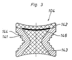
- FIG. 3 Another embodiment of a box-shaped hollow profile for forming relaxation joints in floors and walls is shown in Figure 3.
- the side walls 141 of this one-piece plastic hollow profile spring back like an arrow. They are elastically connected by the soft plastic bridge 142 and the corresponding elastic filling 143.
- a colored insert strip 146 is arranged under the upper clear plastic bridge 142.
- the clamping elements 144 formed on the outside of the side walls 141 and the adhesive or mortar arranged between them serve to clamp the profile to the adjacent fields of a floor or wall.
Landscapes
- Engineering & Computer Science (AREA)
- Architecture (AREA)
- Physics & Mathematics (AREA)
- Electromagnetism (AREA)
- Civil Engineering (AREA)
- Structural Engineering (AREA)
- Floor Finish (AREA)
- Finishing Walls (AREA)
- Road Paving Structures (AREA)
- Forms Removed On Construction Sites Or Auxiliary Members Thereof (AREA)
- Rigid Containers With Two Or More Constituent Elements (AREA)
Claims (4)
- Profilé en forme de caisson en matière plastique pour réaliser des joints de détensionnement dans des planchers ou murs revêtus de plaques en céramique, profilé dans lequel les parois latérales sont constituées d'une matière plastique dure avec éléments d'ancrage et les parois latérales sont reliées entre elles par des entretoises en matière plastique molle, caractérisé en ce que les éléments d'ancrage (411) sont agencés comme des moules creux dans les parois latérales (41) et en ce qu'une bande rapportée colorée (47, 146) est insérée en dessous de l'entretoise en matière plastique molle (42, 46, 142) visible à partir du haut.
- Profité selon la revendication 1, caractérisé en ce que les deux parois latérales (41, 141) sont reliées entre elles additionnellement par une entretoise inférieure (43) en matière plastique molle.
- Profité selon la revendication 2, caractérisé en ce que sur l'entretoise inférieure en matière plastique molle (43) sont respectivement formées des membrures étastiques (45) profilées en forme de tuyau souple et pourvues de nervures de déchirement (44).
- Profité selon la revendication 1, caractérisé en ce qu'il est prévu sur les parois latérales (41) des éléments d'ancrage (411) dans lesquels sont situées des rainures servant de moule creux, ces éléments agissant dans la direction transversale des parois latérales, ayant un profil dépouillé et étant décalés en retrait par rapport au plan extérieur de paroi latérale.
Priority Applications (1)
| Application Number | Priority Date | Filing Date | Title |
|---|---|---|---|
| AT87117720T ATE68840T1 (de) | 1987-01-17 | 1987-12-01 | Kastenfoermiges profil aus kunststoff zur ausbildung von entspannungsfugen in boeden und waenden. |
Applications Claiming Priority (2)
| Application Number | Priority Date | Filing Date | Title |
|---|---|---|---|
| DE3701220 | 1987-01-17 | ||
| DE19873701220 DE3701220A1 (de) | 1987-01-17 | 1987-01-17 | Kastenfoermiges profil aus kunststoff zur ausbildung von entspannungsfugen in boeden und waenden |
Publications (3)
| Publication Number | Publication Date |
|---|---|
| EP0275423A2 EP0275423A2 (fr) | 1988-07-27 |
| EP0275423A3 EP0275423A3 (en) | 1989-07-19 |
| EP0275423B1 true EP0275423B1 (fr) | 1991-10-23 |
Family
ID=6318982
Family Applications (1)
| Application Number | Title | Priority Date | Filing Date |
|---|---|---|---|
| EP87117720A Expired - Lifetime EP0275423B1 (fr) | 1987-01-17 | 1987-12-01 | Profilé rectangulaire en plastique pour l'exécution de joints de dilatation dans des sols ou murs |
Country Status (5)
| Country | Link |
|---|---|
| EP (1) | EP0275423B1 (fr) |
| AT (1) | ATE68840T1 (fr) |
| CA (1) | CA1295146C (fr) |
| DE (2) | DE3701220A1 (fr) |
| ES (1) | ES2025621T3 (fr) |
Families Citing this family (3)
| Publication number | Priority date | Publication date | Assignee | Title |
|---|---|---|---|---|
| DE4141138C2 (de) * | 1991-12-13 | 1993-11-11 | Schlueter Systems Gmbh | Vorrichtung zur Ausbildung einer Dehnungsfuge in einem mit Keramikplatten belegten Boden |
| GB9413161D0 (en) * | 1994-06-30 | 1994-08-24 | Donmini Limited | Spacer assembly |
| EP1983157A1 (fr) * | 2007-04-20 | 2008-10-22 | Sika Technology AG | Dispositif destiné à étanchéifier un passage organisé d'un élément de perçage dans une bande de joint |
Family Cites Families (4)
| Publication number | Priority date | Publication date | Assignee | Title |
|---|---|---|---|---|
| DE7340561U (de) * | 1974-02-28 | Kaldenberg K | Abdeckleiste zum Abdecken von Dehnungsfugen in Bauwerken | |
| DE3503395A1 (de) * | 1985-02-01 | 1986-08-14 | Werner 5860 Iserlohn Schlüter | Vorrichtung zur bildung von dehnungsfugen in estrich- oder betonflaechen |
| DE3508262A1 (de) * | 1985-02-01 | 1986-08-14 | Wedi, Stephan, 4407 Emsdetten | Bewegungsfugenleiste fuer fussbodenkonstruktionen |
| DE8502738U1 (de) * | 1985-02-01 | 1985-10-10 | Schlüter, Werner, 5860 Iserlohn | Vorrichtung zur Bildung von Dehnungsfugen in Böden oder Wänden mit starren Belägen, insbesondere mit Keramikplatten |
-
1987
- 1987-01-17 DE DE19873701220 patent/DE3701220A1/de not_active Withdrawn
- 1987-12-01 DE DE8787117720T patent/DE3774104D1/de not_active Expired - Lifetime
- 1987-12-01 ES ES198787117720T patent/ES2025621T3/es not_active Expired - Lifetime
- 1987-12-01 AT AT87117720T patent/ATE68840T1/de not_active IP Right Cessation
- 1987-12-01 EP EP87117720A patent/EP0275423B1/fr not_active Expired - Lifetime
-
1988
- 1988-01-15 CA CA000556628A patent/CA1295146C/fr not_active Expired - Lifetime
Also Published As
| Publication number | Publication date |
|---|---|
| ATE68840T1 (de) | 1991-11-15 |
| EP0275423A3 (en) | 1989-07-19 |
| DE3774104D1 (de) | 1991-11-28 |
| DE3701220A1 (de) | 1988-07-28 |
| CA1295146C (fr) | 1992-02-04 |
| EP0275423A2 (fr) | 1988-07-27 |
| ES2025621T3 (es) | 1992-04-01 |
Similar Documents
| Publication | Publication Date | Title |
|---|---|---|
| EP0546296B1 (fr) | Dispositif de perfectionnement d'un joint de dilatation dans un sol couvert par des carreaux de céramique | |
| DE4141600C1 (fr) | ||
| DE69102657T2 (de) | Verfahren und Vorrichtung zur Herstellung einer Mauer aus Glasblocksteinen. | |
| EP0991828B1 (fr) | Systeme de chevauchement | |
| EP0547347B1 (fr) | Dispositif de perfectionnement d'un raccord de jonction entre deux surfaces adjacentes à angle droit avec des garnitures rigides | |
| EP0194435A2 (fr) | Dispositif pour la réalisation de joints d'expansion dans des surfaces de plancher ou de béton | |
| EP0281013A2 (fr) | Dalle élastique pour passages à niveau de voies ferrées | |
| DE2910796A1 (de) | Vorrichtung zum verlegen von fliesen u.dgl. | |
| DE3231779C2 (de) | Elastisch nachgiebige Sicherheitsbelagsplatte, insbesondere für Spielfelder | |
| DE2455775C3 (de) | Dehnfugenleiste für Estrichböden | |
| EP0275423B1 (fr) | Profilé rectangulaire en plastique pour l'exécution de joints de dilatation dans des sols ou murs | |
| DE19938184B4 (de) | Plattenelement zur Verwendung als Fußbodenbelag oder Wandverkleidung | |
| EP0027569A1 (fr) | Panneau de façade en une matière moulable | |
| DE3503394C2 (fr) | ||
| DE60131133T2 (de) | Profil zur Fugenüberbrückung, von Belägen, insbesondere für Fußböden | |
| DE3505458A1 (de) | Verfahren zur herstellung eines hohlraumbodens | |
| DE8700777U1 (de) | Kastenförmiges Profil aus Kunststoff zur Ausbildung von Entspannungsfugen in Böden und Wänden | |
| WO2001059231A1 (fr) | Ecarteur | |
| DE3508262C2 (fr) | ||
| DE9116524U1 (de) | Kastenförmiges Profil aus Kunststoff zur Ausbildung von Entspannungsfugen in mit Keramikplatten belegten Böden oder Wänden | |
| DE19823357A1 (de) | Fliese | |
| DE29710530U1 (de) | Vorrichtung zur Ausfüllung von Fugen in Böden oder Wänden | |
| EP1128001A2 (fr) | Dispositif de constitution de joints de dilatation entre des champs de revêtement de sol posés sur un sol brut | |
| DE2329542C3 (de) | Sicherheitsbelagplatte | |
| DE9117281U1 (de) | Vorrichtung zur Ausbildung einer Dehnungsfuge in einem mit Keramikplatten belegten Boden |
Legal Events
| Date | Code | Title | Description |
|---|---|---|---|
| PUAI | Public reference made under article 153(3) epc to a published international application that has entered the european phase |
Free format text: ORIGINAL CODE: 0009012 |
|
| AK | Designated contracting states |
Kind code of ref document: A2 Designated state(s): AT BE CH DE ES FR GB IT LI LU NL SE |
|
| PUAL | Search report despatched |
Free format text: ORIGINAL CODE: 0009013 |
|
| AK | Designated contracting states |
Kind code of ref document: A3 Designated state(s): AT BE CH DE ES FR GB IT LI LU NL SE |
|
| 17P | Request for examination filed |
Effective date: 19890831 |
|
| 17Q | First examination report despatched |
Effective date: 19900709 |
|
| GRAA | (expected) grant |
Free format text: ORIGINAL CODE: 0009210 |
|
| AK | Designated contracting states |
Kind code of ref document: B1 Designated state(s): AT BE CH DE ES FR GB IT LI LU NL SE |
|
| PG25 | Lapsed in a contracting state [announced via postgrant information from national office to epo] |
Ref country code: SE Effective date: 19911023 |
|
| REF | Corresponds to: |
Ref document number: 68840 Country of ref document: AT Date of ref document: 19911115 Kind code of ref document: T |
|
| ITF | It: translation for a ep patent filed | ||
| REF | Corresponds to: |
Ref document number: 3774104 Country of ref document: DE Date of ref document: 19911128 |
|
| ET | Fr: translation filed | ||
| PG25 | Lapsed in a contracting state [announced via postgrant information from national office to epo] |
Ref country code: LU Free format text: LAPSE BECAUSE OF NON-PAYMENT OF DUE FEES Effective date: 19911231 |
|
| PGFP | Annual fee paid to national office [announced via postgrant information from national office to epo] |
Ref country code: NL Payment date: 19911231 Year of fee payment: 5 |
|
| GBT | Gb: translation of ep patent filed (gb section 77(6)(a)/1977) | ||
| PGFP | Annual fee paid to national office [announced via postgrant information from national office to epo] |
Ref country code: CH Payment date: 19920120 Year of fee payment: 5 |
|
| REG | Reference to a national code |
Ref country code: ES Ref legal event code: FG2A Ref document number: 2025621 Country of ref document: ES Kind code of ref document: T3 |
|
| PLBE | No opposition filed within time limit |
Free format text: ORIGINAL CODE: 0009261 |
|
| STAA | Information on the status of an ep patent application or granted ep patent |
Free format text: STATUS: NO OPPOSITION FILED WITHIN TIME LIMIT |
|
| 26N | No opposition filed | ||
| PGFP | Annual fee paid to national office [announced via postgrant information from national office to epo] |
Ref country code: GB Payment date: 19921020 Year of fee payment: 6 |
|
| PGFP | Annual fee paid to national office [announced via postgrant information from national office to epo] |
Ref country code: ES Payment date: 19921127 Year of fee payment: 6 |
|
| PGFP | Annual fee paid to national office [announced via postgrant information from national office to epo] |
Ref country code: FR Payment date: 19921216 Year of fee payment: 6 |
|
| PGFP | Annual fee paid to national office [announced via postgrant information from national office to epo] |
Ref country code: AT Payment date: 19921229 Year of fee payment: 6 |
|
| PG25 | Lapsed in a contracting state [announced via postgrant information from national office to epo] |
Ref country code: LI Effective date: 19921231 Ref country code: CH Effective date: 19921231 |
|
| PGFP | Annual fee paid to national office [announced via postgrant information from national office to epo] |
Ref country code: BE Payment date: 19930108 Year of fee payment: 6 |
|
| PG25 | Lapsed in a contracting state [announced via postgrant information from national office to epo] |
Ref country code: NL Effective date: 19930701 |
|
| NLV4 | Nl: lapsed or anulled due to non-payment of the annual fee | ||
| REG | Reference to a national code |
Ref country code: CH Ref legal event code: PL |
|
| PG25 | Lapsed in a contracting state [announced via postgrant information from national office to epo] |
Ref country code: GB Effective date: 19931201 Ref country code: AT Effective date: 19931201 |
|
| PG25 | Lapsed in a contracting state [announced via postgrant information from national office to epo] |
Ref country code: BE Effective date: 19931231 |
|
| BERE | Be: lapsed |
Owner name: SCHLUTER WERNER Effective date: 19931231 |
|
| GBPC | Gb: european patent ceased through non-payment of renewal fee |
Effective date: 19931201 |
|
| PG25 | Lapsed in a contracting state [announced via postgrant information from national office to epo] |
Ref country code: FR Effective date: 19940831 |
|
| REG | Reference to a national code |
Ref country code: FR Ref legal event code: ST |
|
| PG25 | Lapsed in a contracting state [announced via postgrant information from national office to epo] |
Ref country code: ES Free format text: LAPSE BECAUSE OF NON-PAYMENT OF DUE FEES Effective date: 19941202 |
|
| PGFP | Annual fee paid to national office [announced via postgrant information from national office to epo] |
Ref country code: DE Payment date: 19961210 Year of fee payment: 10 |
|
| PG25 | Lapsed in a contracting state [announced via postgrant information from national office to epo] |
Ref country code: DE Free format text: LAPSE BECAUSE OF NON-PAYMENT OF DUE FEES Effective date: 19980901 |
|
| REG | Reference to a national code |
Ref country code: ES Ref legal event code: FD2A Effective date: 19950112 |
|
| PG25 | Lapsed in a contracting state [announced via postgrant information from national office to epo] |
Ref country code: IT Free format text: LAPSE BECAUSE OF NON-PAYMENT OF DUE FEES;WARNING: LAPSES OF ITALIAN PATENTS WITH EFFECTIVE DATE BEFORE 2007 MAY HAVE OCCURRED AT ANY TIME BEFORE 2007. THE CORRECT EFFECTIVE DATE MAY BE DIFFERENT FROM THE ONE RECORDED. Effective date: 20051201 |