EP0275087A2 - Connecteur avec manchon entourant des fibres optiques - Google Patents
Connecteur avec manchon entourant des fibres optiques Download PDFInfo
- Publication number
- EP0275087A2 EP0275087A2 EP88100339A EP88100339A EP0275087A2 EP 0275087 A2 EP0275087 A2 EP 0275087A2 EP 88100339 A EP88100339 A EP 88100339A EP 88100339 A EP88100339 A EP 88100339A EP 0275087 A2 EP0275087 A2 EP 0275087A2
- Authority
- EP
- European Patent Office
- Prior art keywords
- sleeve
- area
- optical fibers
- receiving part
- connecting part
- Prior art date
- Legal status (The legal status is an assumption and is not a legal conclusion. Google has not performed a legal analysis and makes no representation as to the accuracy of the status listed.)
- Granted
Links
Images


Classifications
-
- G—PHYSICS
- G02—OPTICS
- G02B—OPTICAL ELEMENTS, SYSTEMS OR APPARATUS
- G02B6/00—Light guides; Structural details of arrangements comprising light guides and other optical elements, e.g. couplings
- G02B6/24—Coupling light guides
- G02B6/36—Mechanical coupling means
- G02B6/38—Mechanical coupling means having fibre to fibre mating means
- G02B6/3801—Permanent connections, i.e. wherein fibres are kept aligned by mechanical means
- G02B6/3802—Assembly tools, e.g. crimping tool or pressing bench
-
- G—PHYSICS
- G02—OPTICS
- G02B—OPTICAL ELEMENTS, SYSTEMS OR APPARATUS
- G02B6/00—Light guides; Structural details of arrangements comprising light guides and other optical elements, e.g. couplings
- G02B6/24—Coupling light guides
- G02B6/36—Mechanical coupling means
- G02B6/38—Mechanical coupling means having fibre to fibre mating means
- G02B6/3801—Permanent connections, i.e. wherein fibres are kept aligned by mechanical means
- G02B6/3806—Semi-permanent connections, i.e. wherein the mechanical means keeping the fibres aligned allow for removal of the fibres
Definitions
- the invention relates to a connecting device with a receiving part surrounding the optical waveguide, in which the contact pressure is exerted by at least one sleeve seated on the outside of the receiving part, the receiving part having at least one area with a reduced outside diameter and at least one area with an enlarged outside diameter and the joint of the optical fibers is in the range of the enlarged outer diameter.
- EP 0 045 594 discloses a connecting device in which two optical fibers to be coupled are clamped and centered by two sleeves that can be pushed on in the direction of the joint area. By pushing on the sleeves, the joint area is pressed radially inwards, whereby the optical fibers between round rods are axially aligned and clamped.
- the joint area is not completely covered by the sleeves in the assembled state, which can prove disadvantageous when coupling optical fibers with different or non-circular cross sections.
- connecting devices designed in this way can hardly be subjected to tensile loads, since the coated end regions of the inserted optical waveguides are not sufficiently fixed.
- the invention has for its object to provide a tensile connection device with which two different thickness optical fibers can be easily and precisely connected to each other.
- non-circular optical fibers or those with different diameters can also be reliably coupled.
- the optical fibers are clamped with their sheathing to the receiving part, so that the tensile loads that often occur during use are not transmitted to the joint.
- the joint of the two optical fibers is protected as much as possible and coupling loss is reduced to a minimum.
- the first optical fiber is fixed independently of the second using two or three sleeves. Since the first optical fiber is additionally secured against axial displacement, the second optical fiber can be coupled in a particularly simple manner during practical assembly.
- FIG. 1 and 2 show a connecting device VE1 consisting of two half cylinders HZ11 and HZ12 and a metal sleeve HS1.
- the two half-cylinders HZ11 and HZ12 with their flat mating surfaces PF1 and PF2 together form the receiving part AT1, which has coaxial bores BOG and BOK with the diameters BOG1 and BOK1 in its interior.
- a pressing area PB1 and an immediately adjoining end area EB11, as well as the other end area EB12, have the outer diameter DG1.
- the receiving part AT1 has a partial area TB1 with a reduced outer diameter DK1, in which the sleeve HS1 is in the unassembled state with sufficient play.
- the transitions between the outer diameters DG1 and DK1 are preferably conical.
- the holes BOG with their larger inner diameter BOG1 which extend into the edge areas of the pressing area PB1, these larger holes BOG then tapering into a hole BOK with a smaller inner diameter BOK1.
- the joint ST of the bare (stripped) optical fibers LWF1 and LWF2 in the area of the smaller hole BOK is located approximately in the middle of the press area PB1.
- the outer diameter DG1 of the press area PB1 is somewhat larger than the inner diameter DH1 of the sleeve HS1, so that the sleeve HS1 can be pushed onto the press area PB1 with a press fit.
- the procedure is such that the optical waveguides LWM1 and LWM2 to be coupled are introduced into the bores BOG of the end regions EB11 and EB12 in such a way that the stripped optical fibers LWF1 and LWF2 abut one another in the joint region STB1.
- the joint ST comes to lie in the middle of the joint area STB1 and the sheathed optical fibers LWM1 and LWM2 end before the two transitions from the larger hole BOG to the smaller hole BOK.
- the sleeve HS1 is pushed onto the pressing area PB1.
- the two half cylinders HZ11 and HZ12 which are made of elastic material, are evenly radially compressed and pressed onto the optical fibers LWF1 and LWF2.
- the pressing area PB1 which essentially corresponds to the length of the sleeve HS1, is expediently chosen so that it contains the stripped optical fibers LWF1 and LWF2 as well as part of the stripped optical fibers LWM1 and LWM2.
- the position of the pushed-on sleeve HS1 in the fully assembled state is shown in FIG. 1 with dashed lines. Since the end areas of the coated optical waveguides LWM1 and LWM2 are also pressed with the receiving part AT1, effective strain relief of the joint area STB1 is guaranteed.
- FIG. 3 shows a further embodiment of a connecting device designated VE2 with two sleeves HS21 and HS22.
- the two flat half-cylinders HZ21 and HZ22 with their bores BOG and BOK form the hollow cylindrical receiving part AT2.
- the joint area STB2 and the immediately adjoining end area EB22 together form the wider contact area PB21, while the end area EP21 is provided as a second, narrower contact area PB22.
- an optical fiber can be independent of this arrangement a second are clamped, with which a better centering is achieved, in particular with optical fibers of different thicknesses.
- the first optical fiber (not shown here) is inserted from the left into the BOG hole, which begins at the end area EB21, until the sheathing of the optical fiber is in contact with the diameter transition to the smaller hole BOK, whereby the stripped optical fiber should extend approximately in the middle of the joint area STB (see Figure 1). Since the inner diameters DH2 of the sleeves HS21 and HS22 are somewhat smaller than the outer diameters DG2 of the receiving part AT2, pushing the sleeve HS22 in advance ensures that the first optical fiber is securely clamped to the receiving part AT2. From the right, the second optical fiber is inserted into the BOG hole in the end area EB22 until it collides with the first already fixed optical fiber.
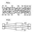
- connection device VE3 consisting of three sleeves HS31, HS32 and HS33 is shown in FIG.
- the inner diameter DH3 of the sleeves HS31, HS32 and HS33 are slightly smaller than the outer diameter DG3 of the receiving part AT3.
- the partial areas TB31 and TB32 have a smaller outer diameter DK3 and are designed such that in the unassembled state the longer partial area TB31 can carry the sleeves HS31 and HS32, the shorter partial area TB32 the sleeve HS33 with sufficient play.
- the holes BOG which begin concentrically through the receiving part AT3 and which start at the end faces of the end areas EB31 and EB32, for receiving the uncovered optical fibers taper at the edges of the pressing area PB33 to the smaller hole BOK, which can receive the uncovered optical fibers.
- a first optical fiber is inserted into the bore BOG that runs out at the end region EB31 in such a way that the stripped optical fiber ends approximately in the middle of the pressing region PB33 and the sheathing at the diameter transition of the bores BOG and BOK ends at the latest.
- the left (sheathed) optical fiber is clamped in the end area EB31 with the receiving part AT3 and held in its position tensile.
- a second optical fiber is then inserted from the right side until it collides with the first and, analogously to the first optical fiber, is clamped by the sleeve HS33 in the end region EB32 together with its sheathing.
- the two half cylinders for example HZ31 and HZ32, can therefore be kept at a distance from each other in the central area, as shown in FIG shown below. This can be achieved, for example, by longitudinal or transverse prestressing of the two half cylinders, for example HZ31, HZ32, or else by resilient intermediate parts which press the two half cylinders, for example HZ31, HZ32 apart, in the untensioned state.
- an immersion liquid can be inserted into the BOK bore in the receiving part, e.g. AT3 are introduced. Care should be taken to ensure that the excess immersion liquid can escape when the optical fibers are introduced, which can be caused by a STB3 attached transverse groove is to be guaranteed.
- the half cylinders HZ11 to HZ32 used in the exemplary embodiments according to the invention can consist of metal, glass, ceramic or plastic. They are preferably made of thermoplastic, which is filled with glass, mineral or carbon fibers to reduce the coefficient of thermal expansion. Materials of this type can be produced inexpensively using injection molding or pressing technology and have a certain elasticity, so that two optical fibers with different diameters can be centered precisely.
- the spring properties of the connecting device can be improved by rib-shaped projections on the surfaces of the half cylinders, for example HZ31, HZ32, or by axially slotted sleeves, for example HS31 to HS33.
- rib-shaped projections on the surfaces of the half cylinders, for example HZ31, HZ32, or by axially slotted sleeves, for example HS31 to HS33.
- nose-shaped projections can be provided on the outer sides of the pressing areas PB31 to PB33 and corresponding corresponding depressions in the edge areas of the sleeves, for example HS31 to HS33 will.
- FIG. 6 shows a hand tool ZA as an assembly aid for the connecting device VE1 to VE3 (VE1 from FIG. 1 is shown).
- a jaw B1 with the larger recess AS1 encloses the end region of the sleeve HS1 to be pressed on, while the other jaw B2, which does not touch the inserted optical fiber due to its elongated recess AS2, encloses the end region EB11.
- a stop AN for receiving the receiving part AT1 and an insertion aid EFH for the optical fiber are expediently attached to the jaw B2.
Priority Applications (1)
| Application Number | Priority Date | Filing Date | Title |
|---|---|---|---|
| AT88100339T ATE89931T1 (de) | 1987-01-15 | 1988-01-12 | Verbindungseinrichtung mit einem die lichtwellenleiter umgebenden aufnahmeteil. |
Applications Claiming Priority (2)
| Application Number | Priority Date | Filing Date | Title |
|---|---|---|---|
| DE3701038 | 1987-01-15 | ||
| DE3701038 | 1987-01-15 |
Publications (3)
| Publication Number | Publication Date |
|---|---|
| EP0275087A2 true EP0275087A2 (fr) | 1988-07-20 |
| EP0275087A3 EP0275087A3 (en) | 1988-09-07 |
| EP0275087B1 EP0275087B1 (fr) | 1993-05-26 |
Family
ID=6318891
Family Applications (1)
| Application Number | Title | Priority Date | Filing Date |
|---|---|---|---|
| EP88100339A Expired - Lifetime EP0275087B1 (fr) | 1987-01-15 | 1988-01-12 | Connecteur avec manchon entourant des fibres optiques |
Country Status (4)
| Country | Link |
|---|---|
| US (1) | US4824203A (fr) |
| EP (1) | EP0275087B1 (fr) |
| AT (1) | ATE89931T1 (fr) |
| DE (1) | DE3881221D1 (fr) |
Cited By (1)
| Publication number | Priority date | Publication date | Assignee | Title |
|---|---|---|---|---|
| USRE35935E (en) * | 1989-09-05 | 1998-10-27 | Labinal Components And Systems, Inc. | Fiber optic connectors |
Families Citing this family (4)
| Publication number | Priority date | Publication date | Assignee | Title |
|---|---|---|---|---|
| US5390270A (en) * | 1989-11-28 | 1995-02-14 | Kel Corporation | Optical fiber ferrule assemblies |
| US5317663A (en) * | 1993-05-20 | 1994-05-31 | Adc Telecommunications, Inc. | One-piece SC adapter |
| US20090034918A1 (en) * | 2007-07-31 | 2009-02-05 | William Eric Caldwell | Fiber optic cables having coupling and methods therefor |
| US8382383B2 (en) * | 2009-06-23 | 2013-02-26 | Pgs Geophysical As | Structure for optical connector ferrule and method for making |
Citations (4)
| Publication number | Priority date | Publication date | Assignee | Title |
|---|---|---|---|---|
| DE2701436A1 (de) * | 1976-01-14 | 1977-07-21 | Thomson Csf | Loesbare verbindungsvorrichtung fuer lichtleitfasern |
| DE2616873A1 (de) * | 1976-04-15 | 1977-11-03 | Siemens Ag | Spleisselement fuer lichtwellenleiter mit zentrierenden fuehrungssegmenten |
| GB1580061A (en) * | 1978-05-09 | 1980-11-26 | Standard Telephones Cables Ltd | Fibre optic connector |
| EP0125525A2 (fr) * | 1983-05-13 | 1984-11-21 | Allied Corporation | Manchon d'alignement pour connecteurs de fibres optiques |
Family Cites Families (1)
| Publication number | Priority date | Publication date | Assignee | Title |
|---|---|---|---|---|
| US4370022A (en) * | 1980-08-01 | 1983-01-25 | Amp Incorporated | Biconical optical waveguide splice |
-
1988
- 1988-01-12 AT AT88100339T patent/ATE89931T1/de not_active IP Right Cessation
- 1988-01-12 DE DE8888100339T patent/DE3881221D1/de not_active Expired - Fee Related
- 1988-01-12 EP EP88100339A patent/EP0275087B1/fr not_active Expired - Lifetime
- 1988-01-14 US US07/143,752 patent/US4824203A/en not_active Expired - Fee Related
Patent Citations (4)
| Publication number | Priority date | Publication date | Assignee | Title |
|---|---|---|---|---|
| DE2701436A1 (de) * | 1976-01-14 | 1977-07-21 | Thomson Csf | Loesbare verbindungsvorrichtung fuer lichtleitfasern |
| DE2616873A1 (de) * | 1976-04-15 | 1977-11-03 | Siemens Ag | Spleisselement fuer lichtwellenleiter mit zentrierenden fuehrungssegmenten |
| GB1580061A (en) * | 1978-05-09 | 1980-11-26 | Standard Telephones Cables Ltd | Fibre optic connector |
| EP0125525A2 (fr) * | 1983-05-13 | 1984-11-21 | Allied Corporation | Manchon d'alignement pour connecteurs de fibres optiques |
Cited By (1)
| Publication number | Priority date | Publication date | Assignee | Title |
|---|---|---|---|---|
| USRE35935E (en) * | 1989-09-05 | 1998-10-27 | Labinal Components And Systems, Inc. | Fiber optic connectors |
Also Published As
| Publication number | Publication date |
|---|---|
| DE3881221D1 (de) | 1993-07-01 |
| EP0275087B1 (fr) | 1993-05-26 |
| ATE89931T1 (de) | 1993-06-15 |
| EP0275087A3 (en) | 1988-09-07 |
| US4824203A (en) | 1989-04-25 |
Similar Documents
| Publication | Publication Date | Title |
|---|---|---|
| DE2943180C2 (de) | Lichtleiter-Steckverbinder | |
| DE2726913C3 (de) | Vorrichtung zum Verbinden zweier ummantelter Einzellichtleitfasern | |
| EP0284658B1 (fr) | Dispositif de connexion pour deux guides d'ondes lumineuses | |
| DE2922705C2 (de) | Verbinder für optische Fasern | |
| DE2626907C2 (de) | Kupplung für optische Fasern | |
| DE2518319C2 (de) | Loesbare Spleissverbindung fuer Lichtwellenleiterkabel | |
| DE3300722A1 (de) | Leitungsverbinder fuer faseroptische leitungen | |
| DE2314687A1 (de) | Verbindungsvorrichtung fuer optische fasern | |
| DE2512330B2 (de) | Steckverbindung für ummantelte Lichtleitfasern aus Quarzglas oder Glas | |
| WO1994017433A1 (fr) | Support | |
| EP0864888A1 (fr) | Connecteur pour une connexion enfichable optique et procédé pour sa fabrication | |
| EP1006378A1 (fr) | Connexion enfichable comportant une pluralité de guides d'onde disposés en parallel | |
| DE3517388A1 (de) | Anschlussteil fuer ein faser-optisches kabel | |
| DE2744814A1 (de) | Stecker fuer optische wellenleiter fuer kabel mit mehreren wellenleitern | |
| DE202009006991U1 (de) | Kabelmuffe | |
| DE2722612A1 (de) | Verbindung fuer lichtleitfasern mit schutzummantelung | |
| EP0275087B1 (fr) | Connecteur avec manchon entourant des fibres optiques | |
| DE2824507C2 (de) | Steckvorrichtung zur elektromagnetischen Kopplung von optischen Faserleitern | |
| DE2747203C2 (fr) | ||
| DE2710945B2 (de) | Verfahren und einrichtung zum verbinden von zwei lichtleitkabeln an ort und stelle | |
| EP2590279A2 (fr) | Dispositif d'introduction d'un élément élastique à la flexion | |
| EP0340867B1 (fr) | Méthode et dispositif pour monter une multipicité de guides d'ondes lumineuses dans une pince étau | |
| DE3005918A1 (de) | Steckerstift fuer lichleitfaser-steckverbindungen und verfahren zur verbindung eines steckerstiftes mit einer lichtleitfaser | |
| DE2847696A1 (de) | Verbinder fuer optische fasern | |
| DE2652714C2 (de) | Lichtleitersteckverbindung |
Legal Events
| Date | Code | Title | Description |
|---|---|---|---|
| PUAI | Public reference made under article 153(3) epc to a published international application that has entered the european phase |
Free format text: ORIGINAL CODE: 0009012 |
|
| AK | Designated contracting states |
Kind code of ref document: A2 Designated state(s): AT BE CH DE FR GB IT LI NL SE |
|
| PUAL | Search report despatched |
Free format text: ORIGINAL CODE: 0009013 |
|
| AK | Designated contracting states |
Kind code of ref document: A3 Designated state(s): AT BE CH DE FR GB IT LI NL SE |
|
| 17P | Request for examination filed |
Effective date: 19890221 |
|
| 17Q | First examination report despatched |
Effective date: 19910705 |
|
| GRAA | (expected) grant |
Free format text: ORIGINAL CODE: 0009210 |
|
| AK | Designated contracting states |
Kind code of ref document: B1 Designated state(s): AT BE CH DE FR GB IT LI NL SE |
|
| REF | Corresponds to: |
Ref document number: 89931 Country of ref document: AT Date of ref document: 19930615 Kind code of ref document: T |
|
| REF | Corresponds to: |
Ref document number: 3881221 Country of ref document: DE Date of ref document: 19930701 |
|
| ET | Fr: translation filed | ||
| ITF | It: translation for a ep patent filed |
Owner name: STUDIO JAUMANN |
|
| GBT | Gb: translation of ep patent filed (gb section 77(6)(a)/1977) |
Effective date: 19930812 |
|
| PG25 | Lapsed in a contracting state [announced via postgrant information from national office to epo] |
Ref country code: GB Effective date: 19940112 Ref country code: AT Effective date: 19940112 |
|
| PG25 | Lapsed in a contracting state [announced via postgrant information from national office to epo] |
Ref country code: SE Effective date: 19940113 |
|
| PG25 | Lapsed in a contracting state [announced via postgrant information from national office to epo] |
Ref country code: LI Effective date: 19940131 Ref country code: CH Effective date: 19940131 Ref country code: BE Effective date: 19940131 |
|
| PLBE | No opposition filed within time limit |
Free format text: ORIGINAL CODE: 0009261 |
|
| STAA | Information on the status of an ep patent application or granted ep patent |
Free format text: STATUS: NO OPPOSITION FILED WITHIN TIME LIMIT |
|
| 26N | No opposition filed | ||
| BERE | Be: lapsed |
Owner name: SIEMENS A.G. Effective date: 19940131 |
|
| PG25 | Lapsed in a contracting state [announced via postgrant information from national office to epo] |
Ref country code: NL Effective date: 19940801 |
|
| GBPC | Gb: european patent ceased through non-payment of renewal fee |
Effective date: 19940112 |
|
| NLV4 | Nl: lapsed or anulled due to non-payment of the annual fee | ||
| PG25 | Lapsed in a contracting state [announced via postgrant information from national office to epo] |
Ref country code: FR Effective date: 19940930 |
|
| REG | Reference to a national code |
Ref country code: CH Ref legal event code: PL |
|
| PG25 | Lapsed in a contracting state [announced via postgrant information from national office to epo] |
Ref country code: DE Effective date: 19941001 |
|
| REG | Reference to a national code |
Ref country code: FR Ref legal event code: ST |
|
| EUG | Se: european patent has lapsed |
Ref document number: 88100339.6 Effective date: 19940810 |
|
| PG25 | Lapsed in a contracting state [announced via postgrant information from national office to epo] |
Ref country code: IT Free format text: LAPSE BECAUSE OF NON-PAYMENT OF DUE FEES;WARNING: LAPSES OF ITALIAN PATENTS WITH EFFECTIVE DATE BEFORE 2007 MAY HAVE OCCURRED AT ANY TIME BEFORE 2007. THE CORRECT EFFECTIVE DATE MAY BE DIFFERENT FROM THE ONE RECORDED. Effective date: 20050112 |