EP0273221A2 - Rohrverbinder aus Muffe und Einsteckteil - Google Patents
Rohrverbinder aus Muffe und Einsteckteil Download PDFInfo
- Publication number
- EP0273221A2 EP0273221A2 EP87117797A EP87117797A EP0273221A2 EP 0273221 A2 EP0273221 A2 EP 0273221A2 EP 87117797 A EP87117797 A EP 87117797A EP 87117797 A EP87117797 A EP 87117797A EP 0273221 A2 EP0273221 A2 EP 0273221A2
- Authority
- EP
- European Patent Office
- Prior art keywords
- sealing
- retaining ring
- receiving groove
- sealing lip
- pipe connector
- Prior art date
- Legal status (The legal status is an assumption and is not a legal conclusion. Google has not performed a legal analysis and makes no representation as to the accuracy of the status listed.)
- Granted
Links
Images

Classifications
-
- F—MECHANICAL ENGINEERING; LIGHTING; HEATING; WEAPONS; BLASTING
- F16—ENGINEERING ELEMENTS AND UNITS; GENERAL MEASURES FOR PRODUCING AND MAINTAINING EFFECTIVE FUNCTIONING OF MACHINES OR INSTALLATIONS; THERMAL INSULATION IN GENERAL
- F16L—PIPES; JOINTS OR FITTINGS FOR PIPES; SUPPORTS FOR PIPES, CABLES OR PROTECTIVE TUBING; MEANS FOR THERMAL INSULATION IN GENERAL
- F16L17/00—Joints with packing adapted to sealing by fluid pressure
- F16L17/02—Joints with packing adapted to sealing by fluid pressure with sealing rings arranged between outer surface of pipe and inner surface of sleeve or socket
- F16L17/03—Joints with packing adapted to sealing by fluid pressure with sealing rings arranged between outer surface of pipe and inner surface of sleeve or socket having annular axial lips
- F16L17/035—Joints with packing adapted to sealing by fluid pressure with sealing rings arranged between outer surface of pipe and inner surface of sleeve or socket having annular axial lips the sealing rings having two lips parallel to each other
Definitions
- the invention relates generally to a pipe connector made of a sleeve and a plug-in part, in particular for plastic pipes, the sleeve having an input guide section, an end guide section and a widening for a sealing component, which widening from a receiving groove for a retaining ring and a sealing chamber for one connected to the retaining ring , in the non-coupled state in the plug-in direction funnel-shaped sealing cone of the sealing component and the retaining ring has a circumferential compression rib on its inside, which is provided at least towards the input guide section with a bevel that continues as an inclined surface to the insert-side flank of the retaining ring, the retaining ring pressed with the aid of the insertion part over the compression rib into the receiving groove, which, like the retaining ring, has a trapezoidal cross-section, the compression rib also being in the insertion direction of the plug-in part is arranged behind the center of the trapezoidal cross section of the receiving groove and retaining ring and the insert
- Pipe connectors of this type have proven themselves. They are used for underground pipelines, especially for cable protection pipes or cable guide pipes. They are known as two-phase pipe connectors because the sealing component consisting of the retaining ring and sealing cone fulfills a double function. The compression rib of the retaining ring initially causes the insertion part to be centered when the insertion part is pushed in, and the sealing cone then mainly effects a seal.
- the sealing cone is a flexible element, but as a one-piece Full profile made of rubber. It is well known that rubber is incompressible. This results in relatively large insertion forces when inserting the plug-in part into the sleeve. If you reduce the wall thickness of the sealing cone, the sealing effect would be impaired.
- the invention has for its object to further develop a generic pipe connector so that the insertion force required to insert the plug-in part is reduced, but the sealing effect is not impaired.
- the invention teaches that the sealing cone consists of two sealing lips with different radial levels, between which a circumferential spacing ring gap is arranged in the uncoupled state, and that the sealing lip on the pipe axis side projects beyond the sealing lip on the sleeve wall side and beak-shaped up to the radial level of the sealing lip on the sleeve wall is bent.
- the sealing lip on the sleeve wall side can have two or more than two circumferential sealing ribs on the sleeve wall side.
- the sealing lip on the tube axis side is provided with two or more than two circumferential sealing ribs on the tube axis side in the region before the buckle-shaped bend.
- the sealing lip on the sleeve wall generally runs more or less parallel to the pipe axis or sleeve axis. This applies to both the uncoupled state and the coupled state.
- the sealing lip on the tube axis side is drawn a little funnel-shaped in the manner described.
- a preferred embodiment of the Invention is characterized in that the sealing lip on the pipe axis side can be pressed when the plug-in part is pushed onto the sealing lip on the sleeve wall. It is recommended that the arrangement be such that the spacer ring gap begins in the transition area between the retaining ring and the sealing cone.
- the advantages achieved can be seen in the fact that in the case of the pipe connector according to the invention, the insertion force for the plug-in part is considerably reduced for a given sealing action, so that the sealing action is not impaired. It is even possible to achieve an improvement in the sealing effect which occurs when the spacer ring gap is filled with pressurized water, so that its hydrostatic pressure increases the sealing force.
- the radial radial height of the compression rib can be reduced compared to the known embodiment.
- the pipe connector shown in the figures consists of a sleeve 1 and an insert part 2. Both parts can be connected Pipes are molded. In particular, it is plastic pipes, namely those that are used as cable protection, cable routing or pressurized water pipes.
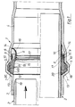
- Fig. 1 the upper part of the figure shows the non-coupled state of the pipe connector according to the invention, when inserting the male part, in the lower part of the coupled state.
- the pipe connector shown in Fig. 1 is e.g. intended for pressurized water pipe.
- the sleeve 1 in turn has an input guide section 3, an end guide section 4 and an expansion 4, 6.
- the widening 5, 6 is made in two pieces. It consists of a receiving groove 5 for the retaining ring 7 of an inserted sealing component, which consists of rubber, plastic or similar materials. It also consists of a sealing chamber 6 for the sealing cone 8, 9 of the sealing component connected to the retaining ring 7.
- An oblique transition part 10 connects both sections of the expansion 5, 6. It goes without saying that the sealing cone 8, 9 is integrally formed on the retaining ring 7. -
- the receiving groove 5 and the retaining ring 7 have a trapezoidal cross section.
- the retaining ring 7 has a circumferential compression rib 11 on its inside, which is provided with a bevel 12 at least towards the input guide section 3, which extends as far as the flank 13 of the receiving groove 5 , albeit with less inclination, continues.
- the result is that the inside width of the retaining ring 7 is larger in this area than the inside width in the input guide section 3 of the sleeve 1 and in the outer diameter of the insert part 2.
- the arrangement is such that the retaining ring 7 with The insertion part 2 is pressed into the receiving groove 5 by means of compression and deformation of the compression rib 11 and consequently experiences an active fixing in the receiving groove 5 during the insertion movement of the insertion part 2.
- the compression rib 11 lies behind the center KR of the trapezoidal cross-section of the receiving groove 5 or retaining ring 7 in the insertion direction of the insert part 2.
- the sealing cone consists of two sealing lips 8, 9 with different radial levels.
- a circumferential spacer ring gap 14 is arranged between the sealing lips 8, 9 in the non-coupled state (cf. FIG. 1 above, FIG. 2).
- the arrangement is such that the sealing lip 8 on the pipe axis side projects beyond the sealing lip 9 on the sleeve wall side in the insertion direction. It is also beak-shaped to the radial level of the sealing lip 9 on the sleeve wall.
- the sealing lip 9 on the sleeve wall side has three circumferential sealing ribs 15 on the sleeve wall side.
- the sealing lip 8 on the tubular axis side also has three circumferential sealing ribs 17 on the tubular axis side in the exemplary embodiment in the exemplary embodiment.
- the lower part of FIG. 1 shows that the Pipe axis-side sealing lip 8 can be pressed when inserting the plug-in part 2 onto the sealing lip 9 on the sleeve wall.
- the spacer ring gap 14 begins in the transition area between the holding ring 7 and the sealing cone 8, 9.
- the sealing lip 8 which is funnel-shaped in the non-coupled state in the insertion direction, has an integrally formed bend 16 which is flared with respect to the sealing lip 8 and which also in the uncoupled state on the inner wall of the sealing chamber 6. Consequently, the spacer ring gap 14 is closed in the uncoupled state and loose base parts can do not enter this spacer ring gap 14.
- a labyrinth seal is formed when the insert part 2 is fully inserted and is created by the sealing ribs 15, 17 resting on the top of the insert part 2 on the one hand and on the inside of the sealing chamber 6 on the other hand.
- the retaining ring 7 can have an additional support ring 18 (for example made of spring steel or plastic) which is embedded in the retaining ring 7, for example vulcanized into it.
- the angle of the chamfer on the compression rib 11 of the retaining ring 7 and the angle of an associated chamfer 19 on the insert part 2 are selected such that they lie outside the area of the self-locking when the insert part 2 is inserted into the sleeve 1.
- the edge 13 is longer than the associated edge 20 on the retaining ring. This avoids that when inserting the plug-in part 2 after passing through the input guide section 3, the plug-in part 2 directly hits the retaining ring 7 and could cause tilting. It is within the scope of the invention that the insert part 2 in the area of the input guide section 3 and 4 to glue.
- a support ring 18 in the retaining ring 7 in the case of large tube dimensions.
- the support ring can be designed as a spring steel ring 18 or consist of hard set plastic or the like.
- the support ring 18 has a stabilizing effect and ensures that the sealing lips 8, 9 function safely as described and that this function is not impaired by the fact that the retaining ring 7 is displaced in the receiving groove 5.
Landscapes
- Engineering & Computer Science (AREA)
- General Engineering & Computer Science (AREA)
- Physics & Mathematics (AREA)
- Fluid Mechanics (AREA)
- Mechanical Engineering (AREA)
- Joints With Sleeves (AREA)
- Quick-Acting Or Multi-Walled Pipe Joints (AREA)
- Orthopedics, Nursing, And Contraception (AREA)
- Measurement Of The Respiration, Hearing Ability, Form, And Blood Characteristics Of Living Organisms (AREA)
- Non-Disconnectible Joints And Screw-Threaded Joints (AREA)
- Seal Device For Vehicle (AREA)
Abstract
Description
- Die Erfindung bezieht sich gattungsgemäß auf einen Rohrverbinder aus Muffe und Einsteckteil, insbesondere für Kunststoffrohre, wobei die Muffe ein Eingangsführungsteilstück, ein Endführungsteilstück sowie eine Aufweitung für ein Dichtungsbauteil aufweist, welche Aufweitung aus einer Aufnahmerille für einen Haltering und einer Dichtungskammer für einen mit dem Haltering verbundenen, im nichtgekuppelten Zustand in Einsteckrichtung trichterförmig zusammenlaufenden Dichtungskonus des Dichtungsbauteils besteht und der Haltering auf seiner Innenseite eine umlaufende Kompressionsrippe besitzt, die zumindest zum Eingangsführungsteilstück hin mit einer Abschrägung versehen ist, die sich bis zur einschubseitigen Flanke des Halteringes als schräggeneigte Fläche fortsetzt, wobei der Haltering mit Hilfe des Einsteckteils über die Kompressionsrippe in die Aufnahmerille gedrückt, die ebenso wie der Haltering trapezförmigen Querschnitt aufweist, wobei ferner die Kompressionsrippe in Einschubrichtung des Einsteckteils hinter dem Mittelpunkt des trapezförmigen Querschnittes von Aufnahmerille und Haltering angeordnet ist und die einschubseitige Flanke der Aufnahmerille länger ist als die zugeordnete Flanke des Halteringes. - Rohrverbinder dieser Art haben sich bewährt. Sie werden bei erdverlegten Rohrleitungen eingesetzt, insbesondere bei Kabelschutzrohren oder Kabelführungsrohren. Sie sind als Zweiphasen-Rohrverbinder bekannt, weil das Dichtungsbauteil aus Haltering und Dichtungskonus eine doppelte Funktion erfüllt. Die Kompressionsrippe des Halteringes bewirkt beim Einschieben des Einsteckteils zunächst eine Zentrierung des Einsteckteils, der Dichtungskonus bewirkt dananch hauptsächlich eine Abdichtung.
- Bei dem bekannten gattungsgemäßen Rohrverbinder (DE 28 00 406) ist der Dichtungkonus zwar ein flexibles Element, jedoch als einteiliges Vollprofil aus Gummi gestaltet. Gummi ist bekanntlich inkompressibel. Daraus resultieren verhältnismäßig große Einschubkräfte beim Einschieben des Einsteckteils in die Muffe. Reduziert man die Wanddicke des Dichtungskonus, so würde man die Dichtwirkung beeinträchtigen.
- Der Erfindung liegt die Aufgabe zugrunde, einen gattungsgemäßen Rohrverbinder so weiter auszubilden, daß die zum Einschieben des Einsteckteils erforderliche Einschubkraft reduizert wird, die Dichtwirkung jedoch nicht beeinträchtigt ist.
- Zur Lösung dieser Aufgabe lehrt die Erfindung, daß der Dichtungskonus aus zwei Dichtungslippen mit unterschiedlichem radialen Niveau besteht, zwischen denen im nichtgekuppelten Zustand ein umlaufender Abstandsringspalt angeordnet ist, und daß die rohrachsenseitige Dichtungslippe in Einsteckrichtung die muffenwandseitige Dichtungslippe überragt sowie schnabelförmig bis auf das radiale Niveau der muffenwandseitigen Dichtungslippe gebogen ist. Die muffenwandseitige Dichtungslippe kann zwei oder mehr als zwei umlaufende, muffenwandseitige Dichtungsrippen aufweisen. Die rohrachsenseitige Dichtungslippe ist nach bevorzugter Ausführungsform der Erfindung im Bereich vor der schnalbförmigen Abbiegung mit zwei oder mehr als zwei umlaufenden rohrachsenseitigen Dichtungsrippen versehen.
- Bei einem erfindungsgemäßen Rohrverbinder verläuft die muffenwandseitige Dichtungslippe im allgemeinen mehr oder weniger parallel zur Rohrachse bzw. Muffenachse. Das gilt sowohl für den nichtgekuppelten Zustand als auch für den gekuppelten Zustand. Demgegenüber ist die rohrachsenseitige Dichtungslippe in der beschriebenen Weise ein wenig trichterförmig zusammengezogen. Eine bevorzugte Ausführungsform der Erfindung ist dadurch gekennzeichnet, daß die rohrachsenseitige Dichtungslippe beim Einschieben des Einsteckteils auf die muffenwandseitige Dichtungslippe preßbar ist. Es empfiehlt sich, die Anordnung so zu treffen, daß der Abstandsringspalt im Übergangsbereich zwischen Haltering und Dichtungskonus beginnt.
- Die erreichten Vorteile sind darin zu sehen, daß bei dem erfindungsgemäßen Rohrverbinder bei vorgegebener Dichtwirkung die Einschubkraft für das Einsteckteil beachtlich reduziert ist, die Dichtwirkung also nicht beeinträchtigt ist. Es läßt sich sogar eine Verbesserung der Dichtwirkung erreichen, die dann eintritt, wenn sich der Abstandsringspalt mit Druckwasser füllt, so daß dessen hydrostatischer Druck die Dichtkraft vergrößert. Um die Einschubkraft weiter zu reduzieren, kann die Kompressionsrippe in ihrer radialen Bauhöhe gegenüber der bekannten Ausführungsform reduziert werden.
- Im folgenden wird die Erfindung anhand einer lediglich ein Ausführungsbeispiel darstellenden Zeichnung ausführlicher erläutert. Es zeigen in schematischer Darstellung
- Fig. 1 eine Längsschnitt durch einen erfindungsgemäßen Rohrverbinder,
- Fig. 2 in gegenüber der Fig. 1 wesentlich vergrößertem Maßstab den Querschnitt des Dichtungsbauteils ausdem Gegenstand nach Fig. 1 im nicht eingebauten Zustand.
- Der in den Figuren dargestellte Rohrverbinder besteht aus einer Muffe 1 und aus einem Einsteckteil 2. Beide Teile können an angeschlossene Rohre angeformt sein. Insbesondere handelt es sich um Kunststoffrohre, und zwar um solche, die als Kabelschutz-, Kabelführungs- oder Druckwasserohre eingesetzt werden.
- In der Fig. 1 ist im oberen Teil der Figur der nichtgekuppelte Zustand des erfindungsgemäßen Rohrverbinders, beim Einschieben des Einsteckteils dargestellt, im unteren Teil der gekuppelte Zustand. Der in der Fig. 1 dargestellte Rohrverbinder ist z.B. für Druckwasserrohr bestimmt. Die Muffe 1 ihrerseits weist ein Eingangsführungsteilstücke 3, ein Endführungsteilstück 4 sowie eine Aufweitung 4, 6 auf. Die Aufweitung 5, 6 ist zweistückig ausgeführt. Sie besteht aus einer Aufnahmerille 5 für den Haltering 7 eines eingelegten Dichtungsbauteils, welches aus Gummi, Kunststoff oder ähnlichen Werkstoffen besteht. Sie besteht fernerhin aus einer Dichtungskammer 6 für den mit dem Haltering 7 verbundenen Dichtungskonus 8, 9 des Dichtungsbauteils. Ein schräge Übergangsteil 10 verbindet beide Teilstücke der Aufweitung 5, 6. Es versteht sich von selbst, daß der Dichtungskonus 8, 9 an den Haltering 7 angeformt ist. - Die Aufnahmerille 5 sowie der Haltering 7 besitzen trapezförmigen Querschnitt.
- Aus einer vergleichenden Betrachtung von Oberteil und Unterteil der Fig. 1 entnimmt man, daß der Haltering 7 auf seiner Innenseite eine umlaufende Kompressionsrippe 11 besitzt, die zumindest zum Eingangsführungsteilstück 3 hin mit einer Anschrägung 12 versehen ist, die sich bis zur Flanke 13 der Aufnahmerille 5, wenn auch mit geringerer Neigung, fortsetzt. Das hat zur Folge, daß die lichte Weite des Halteringes 7 in diesem Bereich größer ist als die lichte Weite im Eingangsführungsteilstück 3 der Muffe 1 und im Außendurchmesser des Einsteckteils 2. Im übrigen ist die Anordnung so getroffen, daß der Haltering 7 mit Hilfe des Einsteckteils 2 über eine Kompression und Verformung der Kompressionsrippe 11 in die Aufnahmerille 5 gedrückt wird und folglich bei der Einführungsbewegung des Einsteckteils 2 eine aktive Festlegung in der Aufnahmerille 5 erfährt. Dazu liegt im Ausführungsbeispiel die Kompressionsrippe 11 in Einschubrichtung des Einsteckteils 2 hinter dem Mittelpunkt KR des trapezförmigen Querschnitts von Aufnahmerille 5 bzw. Haltering 7. Der Dichtungskonus besteht aus zwei Dichtungslippen 8, 9 mit unterschiedlichem radialen Niveau. Zwischen den Dichtungslippen 8, 9 ist im nichtgekuppelten Zustand (vgl. Fig. 1 oben, Fig. 2) ein umlaufender Abstandsringspalt 14 angeordnet. Die Anordnung ist so getroffen, daß die rohrachsenseitige Dichtungslippe 8 in Einsteckrichtung die muffenwandseitige Dichtungslippe 9 überragt. Sie ist im übrigen schnabelförmig bis auf das radiale Niveau der muffenwandseitigen Dichtungslippe 9 gebogen. Im Ausführungsbeispiel besitzt die muffenwandseitige Dichtungslippe 9 drei umlaufende, muffenwanseitige Dichtungsrippen 15. Die rohrachsenseitige Dichtungslippe 8 besitzt im Bereich vor der schnabelförmigen Abbiegung 16 im Ausführungsbeispiel ebenfalls drei umlaufende, hier rohrachsenseitige Dichtungsrippen 17. Aus dem unteren Teil der Fig. 1 entnimmt man, daß die rohrachsenseitige Dichtungslippe 8 beim Einschieben des Einsteckteils 2 auf die muffenwandseitige Dichtungslippe 9 preßbar ist. Der Abstandsringspalt 14 beginnt im Übergangsbereich zwischen Haltering 7 und Dichtungskonus 8, 9.
- Aus dem oberen Teil der Fig. 1 und insbesondere aus der Fig. 2 entnimmt man, daß die Dichtungslippe 8, die im nichtgekuppelten Zustand in Einsteckrichtung trichterförmig zusammengeführt ist, eine angeformte Abbiegung 16 aufweist, die gegenüber der Dichtungslippe 8 konisch erweitert ist und die auch im nichtgekuppelten Zustand an der Innenwand der Dichtungskammer 6 anligt. Folglich ist der Abstandsringspalt 14 im nichtgekuppelten Zustand verschlossen und lose Bodenteile können in diesen Abstandsringspalt 14 nicht eintreten. Eine Labyrinthdichtung kommt zustande, wenn das Einsteckteil 2 vollständig eingeschoben ist, und entsteht durch die Anlage der Dichtungsrippen 15, 17 an der Oberseite des Einsteckteils 2 einerseits, an der Innenseite der Dichtungskammer 6 andererseits. Nur angedeutet wurde in der Figur, daß der Haltering 7 zusätzlichen Stützring 18 (z.B. aus Federstahl oder Kunststoff) aufweisen kann, der in den Haltering 7 eingebettet, z.B. einvulkanisiert ist.
- Der Winkel der Anschrägung an der Kompressionsrippe 11 des Halteringes 7 und der Winkel einer zugeordneten Fase 19 an Einsteckteil 2 sind so gewählt, daß sie bei der Einschubbewegung des Einsteckteils 2 in die Muffe 1 außerhalb des Bereiches der Selbsthemmung liegen. Die Flanke 13 ist länger als die zugeordnete Flanke 20 am Haltering. Dadurch wird vermieden, daß beim Einstecken des Einsteckteils 2 nach Passieren des Eingangsführungsteilstückes 3 das Einsteckteil 2 unmittelbar auf den Haltering 7 stößt und ein Verkanten hervorrufen könnte. Im Rahmen der Erfindung liegt es, daß Einsteckteil 2 im Bereich des Eingangsführungsteilstückes 3 und bei 4 zu verkleben.
- Um sicherzustellen, daß die Dichtungslippe 8 im nichtgekuppelten Zustand eine genau vorgegebene Position einnimmt, ist es zweckmäßig, bei großdimensionierten Rohrabmessungen in den Haltering 7 einen Stützring 18 einzubetten. Der Stützring kann als Federstahlring 18 ausgebildet oder aus hart eingestelltem Kunststoff oder dergleichen bestehen. Der Stützring 18 wirkt stabilisierend und stellt sicher, daß die Dichtungslippen 8, 9 wie beschrieben sicher funktionieren und daß diese Funktion nicht dadurch beeinträchtigt wird, daß sich der Haltering 7 in der Aufnahmerille 5 verschiebt.
Claims (6)
Priority Applications (1)
| Application Number | Priority Date | Filing Date | Title |
|---|---|---|---|
| AT87117797T ATE69867T1 (de) | 1986-12-31 | 1987-12-02 | Rohrverbinder aus muffe und einsteckteil. |
Applications Claiming Priority (3)
| Application Number | Priority Date | Filing Date | Title |
|---|---|---|---|
| DE3644834 | 1986-12-31 | ||
| DE8634927U DE8634927U1 (de) | 1986-12-31 | 1986-12-31 | Rohrverbinder aus Muffe und Einsteckteil |
| DE3644834A DE3644834C1 (de) | 1986-12-31 | 1986-12-31 | Rohrverbinder aus Muffe und Einsteckteil |
Publications (3)
| Publication Number | Publication Date |
|---|---|
| EP0273221A2 true EP0273221A2 (de) | 1988-07-06 |
| EP0273221A3 EP0273221A3 (en) | 1989-07-26 |
| EP0273221B1 EP0273221B1 (de) | 1991-11-27 |
Family
ID=37872296
Family Applications (1)
| Application Number | Title | Priority Date | Filing Date |
|---|---|---|---|
| EP87117797A Expired - Lifetime EP0273221B1 (de) | 1986-12-31 | 1987-12-02 | Rohrverbinder aus Muffe und Einsteckteil |
Country Status (6)
| Country | Link |
|---|---|
| EP (1) | EP0273221B1 (de) |
| DE (2) | DE3644834C1 (de) |
| DK (1) | DK167035B1 (de) |
| ES (1) | ES2028036T3 (de) |
| FI (1) | FI87267C (de) |
| NO (1) | NO174861C (de) |
Cited By (2)
| Publication number | Priority date | Publication date | Assignee | Title |
|---|---|---|---|---|
| EP2492569A3 (de) * | 2006-06-30 | 2012-10-10 | Tiroler Röhren- und Metallwerke Aktiengesellschaft | Muffenverbindung |
| CN116892755A (zh) * | 2023-07-21 | 2023-10-17 | 浙江亚厦装饰股份有限公司 | 一种吊顶空调辐射水管结构 |
Families Citing this family (23)
| Publication number | Priority date | Publication date | Assignee | Title |
|---|---|---|---|---|
| DE9017960U1 (de) * | 1990-11-17 | 1993-03-11 | Dipl.-Ing. Dr. Ernst Vogelsang Gmbh & Co Kg, 4352 Herten | Rohrverbinder aus Muffe und Einsteckteil, insbesondere für Kunststoffrohre |
| USD447223S1 (en) | 1998-11-06 | 2001-08-28 | Lindab Ab | Sealing rings for ventilation ducts |
| DK0999397T3 (da) | 1998-11-06 | 2003-02-24 | Lindab Ab | Rørformet element med forseglingsmidler og fremgangsmåde til fremstilling af det rørformede element |
| USD475779S1 (en) | 2001-03-20 | 2003-06-10 | Eastern Sheet Metal Llc | Offset duct with an indented end |
| USD475448S1 (en) | 2001-03-20 | 2003-06-03 | Eastern Sheet Metal Llc | Duct with an indented end |
| USD501548S1 (en) | 2001-03-20 | 2005-02-01 | Eastern Sheet Metal Llc | Duct tap with an indented end |
| USD521632S1 (en) | 2001-03-20 | 2006-05-23 | Eastern Sheet Metal Llc | Duct with a crimped end |
| USD475780S1 (en) | 2001-03-20 | 2003-06-10 | Eastern Sheet Metal Llc | Duct with a crimped end |
| USD476074S1 (en) | 2001-03-20 | 2003-06-17 | Eastern Sheet Metal Llc | Duct tap with a crimped end |
| USD475447S1 (en) | 2001-03-20 | 2003-06-03 | Eastern Sheet Metal Llc | Bell mouth with an indented end |
| USD523131S1 (en) | 2001-03-20 | 2006-06-13 | Eastern Sheet Metal Llc | Duct with an indented end |
| USD475130S1 (en) | 2001-03-20 | 2003-05-27 | Eastern Sheet Metal Llc | Bell mouth with a crimped end |
| USD527091S1 (en) | 2001-03-20 | 2006-08-22 | Eastern Sheet Metal Llc | Duct with an indented end |
| USD475449S1 (en) | 2001-03-20 | 2003-06-03 | Eastern Sheet Metal Llc | Duct tap with an indented end |
| USD480132S1 (en) | 2001-03-20 | 2003-09-30 | Eastern Sheet Metal Llc | Reducer with an indented end |
| USD475778S1 (en) | 2001-03-20 | 2003-06-10 | Eastern Sheet Metal Llc | Offset duct with a crimped end |
| USD478978S1 (en) | 2001-03-20 | 2003-08-26 | Eastern Sheet Metal Llc | Reducer with a crimped end |
| USD501547S1 (en) | 2001-03-20 | 2005-02-01 | Eastern Sheet Metal Llc | Duct with an indented end |
| USD524436S1 (en) | 2001-03-20 | 2006-07-04 | Eastern Sheet Metal Llc | Duct with a crimped end |
| USD528646S1 (en) | 2001-03-20 | 2006-09-19 | Eastern Sheet Metal Llc | Duct with a crimped end |
| USD521633S1 (en) | 2001-03-20 | 2006-05-23 | Eastern Sheet Metal Llc | Duct tap with a crimped end |
| CN103672225B (zh) * | 2013-11-07 | 2017-02-08 | 苏州中拓专利运营管理有限公司 | 一种转接件 |
| CN104197126A (zh) * | 2014-08-29 | 2014-12-10 | 陈征 | 一种唇密封卡压式管件接头及其安装工艺 |
Family Cites Families (5)
| Publication number | Priority date | Publication date | Assignee | Title |
|---|---|---|---|---|
| FR1421264A (fr) * | 1963-12-20 | 1965-12-17 | Merkel Asbest & Gummiwerke | Joint à manchettes pour assemblages tubulaires par manchons, à démonter de temps en temps |
| DD120076A1 (de) * | 1975-06-16 | 1976-05-20 | ||
| FR2376986A1 (fr) * | 1977-01-07 | 1978-08-04 | Seperef | Dispositif pour l'assemblage de corps tubulaires cylindriques rigides |
| DE2731749C2 (de) * | 1977-07-14 | 1983-05-19 | Dipl.-Ing. Dr. Ernst Vogelsang Gmbh & Co Kg, 4352 Herten | Rohrverbinder |
| DE2800406C2 (de) * | 1978-01-05 | 1983-11-10 | Dipl.-Ing. Dr. Ernst Vogelsang Gmbh & Co Kg, 4352 Herten | Rohrverbinder |
-
1986
- 1986-12-31 DE DE3644834A patent/DE3644834C1/de not_active Expired
- 1986-12-31 DE DE8634927U patent/DE8634927U1/de not_active Expired
-
1987
- 1987-12-02 EP EP87117797A patent/EP0273221B1/de not_active Expired - Lifetime
- 1987-12-02 ES ES198787117797T patent/ES2028036T3/es not_active Expired - Lifetime
- 1987-12-21 FI FI875625A patent/FI87267C/fi not_active IP Right Cessation
- 1987-12-22 NO NO875380A patent/NO174861C/no not_active IP Right Cessation
- 1987-12-30 DK DK692287A patent/DK167035B1/da not_active IP Right Cessation
Cited By (2)
| Publication number | Priority date | Publication date | Assignee | Title |
|---|---|---|---|---|
| EP2492569A3 (de) * | 2006-06-30 | 2012-10-10 | Tiroler Röhren- und Metallwerke Aktiengesellschaft | Muffenverbindung |
| CN116892755A (zh) * | 2023-07-21 | 2023-10-17 | 浙江亚厦装饰股份有限公司 | 一种吊顶空调辐射水管结构 |
Also Published As
| Publication number | Publication date |
|---|---|
| EP0273221B1 (de) | 1991-11-27 |
| FI87267B (fi) | 1992-08-31 |
| NO875380D0 (no) | 1987-12-22 |
| NO875380L (no) | 1988-07-01 |
| NO174861B (no) | 1994-04-11 |
| FI875625A7 (fi) | 1988-07-01 |
| FI87267C (fi) | 1992-12-10 |
| DK692287D0 (da) | 1987-12-30 |
| DE8634927U1 (de) | 1987-05-27 |
| NO174861C (no) | 1994-07-20 |
| DK692287A (da) | 1988-07-01 |
| FI875625A0 (fi) | 1987-12-21 |
| EP0273221A3 (en) | 1989-07-26 |
| ES2028036T3 (es) | 1992-07-01 |
| DE3644834C1 (de) | 1988-04-28 |
| DK167035B1 (da) | 1993-08-16 |
Similar Documents
| Publication | Publication Date | Title |
|---|---|---|
| EP0273221B1 (de) | Rohrverbinder aus Muffe und Einsteckteil | |
| EP0486949B1 (de) | Rohrverbinder aus Muffe und Einsteckteil, insbesondere für Kunststoffrohre | |
| EP0918184B1 (de) | Anschlusselement für Rohre oder Schläuche | |
| DE4020171C1 (de) | ||
| DE2832614A1 (de) | Verbindungsstueck fuer rohrleitungen | |
| DE1153577B (de) | Muffenverbindung fuer Rohre | |
| EP0001385B1 (de) | Dichtungsring für eine Rohrsteckverbindung | |
| DE69322955T2 (de) | Beschichtungsrohr | |
| DE2800406C2 (de) | Rohrverbinder | |
| DE605214C (de) | Dichte Verbindung fuer Rohrleitungen mit in Nuten der Muffe oder der ueber die Stossfuge der Rohre geschobenen Huelse angeordneten Lippendichtungen | |
| EP0622577A1 (de) | Rohrverbindung mit einem Luftpolsterdichtring | |
| DE3605330A1 (de) | Dichtungsmittel fuer die axiale verbindung quergewellter rohre aus kunststoff | |
| DE2731749A1 (de) | Rohrverbinder | |
| EP3869077B1 (de) | Rohradapter | |
| EP0613538B1 (de) | Abdichtung zwischen zwei ineinandersteckbaren teilen | |
| DE29904682U1 (de) | Dichtungsring zum Einsetzen in eine Sicke einer Rohrmuffe | |
| DE6909667U (de) | Muffenverbindung fuer rohre | |
| DE4243353C2 (de) | Vortriebsrohrverbindung für den unterirdischen Schildvortrieb | |
| AT405969B (de) | Vorrichtung zum anschliessen eines rohres an einen schachtboden | |
| DE9417423U1 (de) | Vorrichtung zum abdichtenden Verbinden von Vertriebsrohren aus Beton, Steingut, Inlinerrohren o.dgl. | |
| DE8522753U1 (de) | Längenausgleichs-Vorrichtung für Rohr- oder Schlauchleitungen | |
| DE1177881B (de) | Abdichtende Steckverbindung | |
| DE8604467U1 (de) | Dichtungsring für die axiale Verbindung quergewellter Rohre aus Kunststoff | |
| DE3705683A1 (de) | Dichtring, vorzugsweise fuer kabelkanalrohre oder dergl. | |
| DE29803422U1 (de) | Kunststoffrohr zum Einbringen in eine Fluid-Rohrleitung |
Legal Events
| Date | Code | Title | Description |
|---|---|---|---|
| PUAI | Public reference made under article 153(3) epc to a published international application that has entered the european phase |
Free format text: ORIGINAL CODE: 0009012 |
|
| AK | Designated contracting states |
Kind code of ref document: A2 Designated state(s): AT BE CH ES FR GB IT LI NL SE |
|
| PUAL | Search report despatched |
Free format text: ORIGINAL CODE: 0009013 |
|
| AK | Designated contracting states |
Kind code of ref document: A3 Designated state(s): AT BE CH ES FR GB IT LI NL SE |
|
| 17P | Request for examination filed |
Effective date: 19890812 |
|
| 17Q | First examination report despatched |
Effective date: 19891106 |
|
| GRAA | (expected) grant |
Free format text: ORIGINAL CODE: 0009210 |
|
| AK | Designated contracting states |
Kind code of ref document: B1 Designated state(s): AT BE CH ES FR GB IT LI NL SE |
|
| REF | Corresponds to: |
Ref document number: 69867 Country of ref document: AT Date of ref document: 19911215 Kind code of ref document: T |
|
| ITF | It: translation for a ep patent filed | ||
| GBT | Gb: translation of ep patent filed (gb section 77(6)(a)/1977) | ||
| ET | Fr: translation filed | ||
| REG | Reference to a national code |
Ref country code: ES Ref legal event code: FG2A Ref document number: 2028036 Country of ref document: ES Kind code of ref document: T3 |
|
| PLBE | No opposition filed within time limit |
Free format text: ORIGINAL CODE: 0009261 |
|
| STAA | Information on the status of an ep patent application or granted ep patent |
Free format text: STATUS: NO OPPOSITION FILED WITHIN TIME LIMIT |
|
| 26N | No opposition filed | ||
| EAL | Se: european patent in force in sweden |
Ref document number: 87117797.8 |
|
| PGFP | Annual fee paid to national office [announced via postgrant information from national office to epo] |
Ref country code: GB Payment date: 20011018 Year of fee payment: 15 |
|
| PGFP | Annual fee paid to national office [announced via postgrant information from national office to epo] |
Ref country code: BE Payment date: 20011019 Year of fee payment: 15 |
|
| PGFP | Annual fee paid to national office [announced via postgrant information from national office to epo] |
Ref country code: FR Payment date: 20011024 Year of fee payment: 15 |
|
| PGFP | Annual fee paid to national office [announced via postgrant information from national office to epo] |
Ref country code: ES Payment date: 20011130 Year of fee payment: 15 |
|
| PGFP | Annual fee paid to national office [announced via postgrant information from national office to epo] |
Ref country code: SE Payment date: 20011203 Year of fee payment: 15 |
|
| PGFP | Annual fee paid to national office [announced via postgrant information from national office to epo] |
Ref country code: NL Payment date: 20011220 Year of fee payment: 15 |
|
| PGFP | Annual fee paid to national office [announced via postgrant information from national office to epo] |
Ref country code: CH Payment date: 20011221 Year of fee payment: 15 |
|
| REG | Reference to a national code |
Ref country code: GB Ref legal event code: IF02 |
|
| PG25 | Lapsed in a contracting state [announced via postgrant information from national office to epo] |
Ref country code: GB Free format text: LAPSE BECAUSE OF NON-PAYMENT OF DUE FEES Effective date: 20021202 |
|
| PG25 | Lapsed in a contracting state [announced via postgrant information from national office to epo] |
Ref country code: SE Free format text: LAPSE BECAUSE OF NON-PAYMENT OF DUE FEES Effective date: 20021203 Ref country code: ES Free format text: LAPSE BECAUSE OF NON-PAYMENT OF DUE FEES Effective date: 20021203 |
|
| PG25 | Lapsed in a contracting state [announced via postgrant information from national office to epo] |
Ref country code: LI Free format text: LAPSE BECAUSE OF NON-PAYMENT OF DUE FEES Effective date: 20021231 Ref country code: CH Free format text: LAPSE BECAUSE OF NON-PAYMENT OF DUE FEES Effective date: 20021231 Ref country code: BE Free format text: LAPSE BECAUSE OF NON-PAYMENT OF DUE FEES Effective date: 20021231 |
|
| BERE | Be: lapsed |
Owner name: ERNST *VOGELSANG G.M.B.H. & CO. K.G. Effective date: 20021231 |
|
| PG25 | Lapsed in a contracting state [announced via postgrant information from national office to epo] |
Ref country code: NL Free format text: LAPSE BECAUSE OF NON-PAYMENT OF DUE FEES Effective date: 20030701 |
|
| GBPC | Gb: european patent ceased through non-payment of renewal fee | ||
| EUG | Se: european patent has lapsed | ||
| NLV4 | Nl: lapsed or anulled due to non-payment of the annual fee |
Effective date: 20030701 |
|
| PG25 | Lapsed in a contracting state [announced via postgrant information from national office to epo] |
Ref country code: FR Free format text: LAPSE BECAUSE OF NON-PAYMENT OF DUE FEES Effective date: 20030901 |
|
| REG | Reference to a national code |
Ref country code: CH Ref legal event code: PL |
|
| REG | Reference to a national code |
Ref country code: FR Ref legal event code: ST |
|
| REG | Reference to a national code |
Ref country code: ES Ref legal event code: FD2A Effective date: 20021203 |
|
| PG25 | Lapsed in a contracting state [announced via postgrant information from national office to epo] |
Ref country code: IT Free format text: LAPSE BECAUSE OF NON-PAYMENT OF DUE FEES;WARNING: LAPSES OF ITALIAN PATENTS WITH EFFECTIVE DATE BEFORE 2007 MAY HAVE OCCURRED AT ANY TIME BEFORE 2007. THE CORRECT EFFECTIVE DATE MAY BE DIFFERENT FROM THE ONE RECORDED. Effective date: 20051202 |
|
| PGFP | Annual fee paid to national office [announced via postgrant information from national office to epo] |
Ref country code: AT Payment date: 20061213 Year of fee payment: 20 |