EP0272435B1 - Anordnung zur Verwendung eines Fernsprechtischapparates als Fernsprechwandapparat - Google Patents
Anordnung zur Verwendung eines Fernsprechtischapparates als Fernsprechwandapparat Download PDFInfo
- Publication number
- EP0272435B1 EP0272435B1 EP19870116688 EP87116688A EP0272435B1 EP 0272435 B1 EP0272435 B1 EP 0272435B1 EP 19870116688 EP19870116688 EP 19870116688 EP 87116688 A EP87116688 A EP 87116688A EP 0272435 B1 EP0272435 B1 EP 0272435B1
- Authority
- EP
- European Patent Office
- Prior art keywords
- wall
- telephone
- hook
- arrangement according
- handset
- Prior art date
- Legal status (The legal status is an assumption and is not a legal conclusion. Google has not performed a legal analysis and makes no representation as to the accuracy of the status listed.)
- Expired - Lifetime
Links
- 238000009434 installation Methods 0.000 claims description 3
- 239000000725 suspension Substances 0.000 claims 1
- 230000037431 insertion Effects 0.000 description 1
- 238000003780 insertion Methods 0.000 description 1
Images


Classifications
-
- H—ELECTRICITY
- H04—ELECTRIC COMMUNICATION TECHNIQUE
- H04M—TELEPHONIC COMMUNICATION
- H04M1/00—Substation equipment, e.g. for use by subscribers
- H04M1/02—Constructional features of telephone sets
- H04M1/0297—Telephone sets adapted to be mounted on a desk or on a wall
Definitions
- the invention relates to an arrangement for using a telephony table apparatus consisting of an upper housing shell and a lower housing shell as a telephone wall apparatus, the telephone apparatus having a handset being designed in the form of a desk, the upper side being inclined at an angle of greater than 20 degrees and less than 45 degrees to the contact surface of the telephony table apparatus and the rear wall to the top is arranged at an angle of 80 degrees to 100 degrees, and the telephone set with the rear wall downward attached to a wall can be used as a telephone set.
- the object of the invention is to provide an arrangement which makes it possible to use the proposed telephone table apparatus as a telephone wall unit.
- a wall holder which can be fastened to the wall which has hook-like projections which engage in corresponding openings in the underside of the telephone set and in that the lower housing shell Has openings in which resilient webs of the upper housing shell engage from below and that the hook-like projections engage in these openings from below.
- the wall holder according to the invention is first attached to the wall and then the telephone set is hung into it, whereby it is held by the hook-like projections.
- a wall holder which can be fastened to the wall and which has hook-like projections which engage in corresponding openings in the underside of the telephone set is already known.
- a telephone set base plate is described, which can be snapped into the lower housing shell of a telephone set in one or the other rotated by 180 degrees, in which a position of the telephone set as a table set and in the other position, in which the base plate is attached to the wall, can be used as a wall set.
- the base plate is provided on one side with two fixed lugs and on the opposite side with one or two resilient lugs, wherein the lugs can be snapped into corresponding openings provided for this purpose.
- the lower housing shell is provided with corresponding openings into which the resilient webs of the upper housing shell protrude and engage. Through these openings it is possible to push the resilient webs out of the latching position from below by means of a screwdriver in order to separate the housing shells from one another. A hook-like projection of the wall bracket attached to the wall engages in each of these openings.
- the invention is based on exemplary embodiments explained in more detail, which are shown in the drawing.
- the telephone set consists of an upper 9 and a lower 10 housing shell.
- the wall bracket 1 is first screwed and then the telephone set is mechanically connected to it. This can be done in various ways, as will be described in detail below.
- the telephone set has on its underside (as a table set) a trough 8 which does not extend to the sides of the set housing.
- cable entries 24 are provided on the side for connecting the handset 3, a second handset, etc.
- a hook 5 is attached to the apparatus housing, which hook protrudes into a slot 4 of the handset in the on-hook state. In this state, the rotatably mounted fork switch 25 is actuated.
- One possibility of forming the hook 5 for holding the handset 3 by engaging in the slot 4 is also described in the patent DE-C-3 210 111.
- the wall bracket 1 shown in FIG. 2 consists of a base plate 6 and the two triangular side parts 15 which nestle against the underside of the telephone set housing and each have two hook-shaped projections 7.
- the telephone set housing can additionally be fastened to the wall bracket with a screw which is screwed into the bore 16 of the cylindrical projection 22.
- a cable opening 19 is provided on the corresponding side part 15 for passing the cables leading to the cable bushings 24 (FIG. 1).
- a hook 18 can be provided, which is used to hang up the handset, the hook 18 engaging in the slot 4 of the handset 3 (FIG. 1).
- the base plate 6 is provided with an installation opening 17, the dimensions of which correspond to the standardized sockets and light switches, so that the wall bracket, such as a socket or a light switch, can be fastened to a flush-mounted installation socket, the socket also being used for the electrical connection of the telephone set. If this type of fastening is not used, further fastening holes 23 are present in the base plate 6. Bores 26 are also provided on the wall bracket, which enable a different type of fastening of the apparatus housing to the wall bracket by means of screw connections.
- the upper housing shell 9 has webs 12 which protrude through openings 11 in the lower housing shell 10 and engage with latching openings 27 in the latching lugs 20.
- the connection of the two housing shells can be released by inserting a screwdriver at the bottom into the opening 11 for lifting the resilient web 12.
- the hook-shaped projection 7 of the side part 15 of the wall holder engages in the opening 11, specifically in lugs 21 attached there (FIG. 3).
- the handset 3 has on its underside, namely below the sound outlet openings of the earphone, a slot 4, in which the hook 18 attached to the wall bracket engages and thus holds the handset 3 in the raised state. Furthermore, a bracket 27 is attached to the wall bracket 1, which grips the handset at the end facing away from the insertion of the handset cord (FIG. 4).
- the bracket 27 attached to the wall bracket 1 is provided with a guide 28, and the hook is chamfered on the side facing away from the wall, so that the handset can be easily attached and it is held by the hook 18.
- the bracket 27 with the guide 28 and / or the hook 18 can either be fixed to the wall bracket 1 or be resilient (Figure 5).
Landscapes
- Engineering & Computer Science (AREA)
- Signal Processing (AREA)
- Telephone Set Structure (AREA)
- Casings For Electric Apparatus (AREA)
Description
- Die Erfindung betrifft eine Anordnung zur Verwendung eines aus einer oberen Gehäuseschale und einer unteren Gehäuseschale bestehenden Fernsprechtischapparates als Fernsprechwandapparat, wobei der einen Handapparat aufweisende Fernsprechapparat pultförmig ausgebildet ist, die Oberseite in einem Winkel von größer 20 Grad und kleiner 45 Grad zur Auflagefläche des Fernsprechtischapparates geneigt und die Rückwand zur Oberseite im Winkel von 80 Grad bis 100 Grad angeordnet ist, und der Fernsprechapparat mit der Rückwand nach unten an einer Wand befestigt als Fernsprechapparat benutzbar ist.
- Ein derartiger, pultförmiger ausgebildete Fernsprechapparat ist bereits vorgeschlagen worden, so wird in der nachveröffentlichten DE-A- 36 07 727 ein Fernsprechapparat beschrieben, dessen Oberseite in Richtung zum Benutzer relativ stark geneigt ist, um auf diese Weise bessere Bedienbarkeit und Ablesbarkeit der Tasten und der Anzeigevorrichtung zu ermöglichen. In der genannten Patentanmeldung ist auch Hinweis darauf enthalten, diesen als Fernsprechtischapparat um 180 Grad gedreht an der Wand befestigt auch als Fernsprechwandapparat zu benutzen. Weitergehende Hinweise lassen sich dieser Patentanmeldung nicht entnehmen.
- Die Aufgabe der Erfindung besteht nun darin, eine Anordnung anzugeben, welche es ermöglicht, den vorgeschlagenen Fernsprechtischapparat auch als Fernsprechwandapparat zu benutzen.
- Diese Aufgabe wird dadurch gelöst, daß ein an der Wand befestigbarer Wandhalter vorgesehen ist, welcher hakenartige Vorsprünge aufweist, die in entsprechende Öffnungen der Unterseite des Fernsprechapparates eingreifen und daß die untere Gehäuseschale Öffnungen aufweist, in welche federnde Stege der oberen Gehäuseschale von unten einrasten und daß die hakenartige Vorsprünge in diese Öffnungen von unten einrasten.
- Der erfindungsgemäße Wandhalter wird zunächst an der Wand befestigt und anschließend der Fernsprechapparat in diesen eingehängt, wobei er durch die hakenartigen Vorsprünge gehalten wird.
- Ein an der Wand befestigbare Wandhalter, welcher hakenartige Vorsprünge aufweist, die in entsprechende Öffnungen der Unterseite des Fernsprechapparates eingreifen, ist bereits bekannt. So wird in der US-A- 3 859 476 und in der GB-A- 2 157 915 eine Fernsprechapparategrundplatte beschrieben, welche in die untere Gehäuseschale eines Fernsprechapparates in der einen oder in der anderen um 180 Grad gedrehten Position einrastbar ist, wobei in der einen Position der Fernsprechapparat als Tischapparat und in der anderen Position, in welcher die Grundplatte an der Wand befestigt ist, als Wandapparat verwendbar ist. Dabei ist die Grundplatte auf der einen Seite mit zwei festen Nasen und auf der gegenüberliegenden Seite mit einer bzw. zwei federnden Nasen versehen, wobei die Nasen in entsprechende, hierfür vorgesehene Öffnungen einrastbar sind.
- Bei der erfindungsgemäßen Anordnung ist die untere Gehäuseschale mit entsprechenden Öffnungen versehen, in welche die federnden Stege der oberen Gehäuseschale hineinragen und einrasten. Durch diese Öffnungen ist es möglich, von unten mittels eines Schraubenziehers die federnden Stege aus der rastenden Stellung herauszudrücken, um die Gehäuseschalen voneinander zu lösen. In diese vorhandene Öffnung rastet jeweils ein hakenartiger Vorsprung des an der Wand befestigten Wandhalters ein.
- Die Erfindung wird anhand von Ausführungsbeispielen näher erläutert, welche in der Zeichnung dargestellt sind.
- Es zeigt:
- Fig. 1
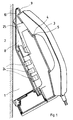
- die Seitenansicht eines an der Wand befestigten Wandhalters mit dem daran angebrachten Fernsprechapparat,
- Fig. 2
- eine Dreiseitenansicht des Wandhalters,
- Fig. 3
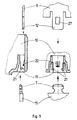
- Einzelheiten zur Befestigung der Gehäuseschalen untereinander und der zusätzlichen Befestigung mit dem Wandhalter und
- Fig. 4
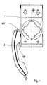
- eine Draufsicht auf den Wandhalter mit dem angehängten Handapparat und
- Fig. 5
- eine Dreiseitenansicht des Wandhalters.
- Der in Fig. 1 gezeigte Fernsprechapaprat ist um 180° gedreht an einer senkrechten Wand 2 befestigt. Der Fernsprechapparat besteht aus einer oberen 9 und einer unteren 10 Gehäuseschale. An der Wand 2 wird zunächst der Wandhalter 1 angeschraubt und mit diesem anschließend der Fernsprechapparat mechanisch verbunden. Dies kann auf verschiedene Weise geschehen, wie dies weiter unten noch ausführlich beschrieben wird. Der Fernsprechapparat weist an seiner Unterseite (als Tischapparat) eine Wanne 8 auf, welche nicht bis zu den Seiten des Apparategehäuses reicht. An dieser Wanne 8 sind seitlich Kabeleinführungen 24 zum Anschluß des Handapparats 3, eines Zweithöreres, usw. vorgesehen. Bei der Verwendung eines Fernsprechtischapparates als Fernsprechwandapparat muß auch die Wählvorrichtung desselben ebenfalls um 180° gedreht werden. Zum Halten des Handapparates 3 auf dem Fernsprechwandapparat ist am Apparategehäuse ein Haken 5 angebracht, welcher in einen Schlitz 4 des Handapparats im aufgelegten Zustand hineinragt. In diesem Zustand wird auch der drehbar gelagerte Gabelumschalter 25 betätigt. Eine Möglichkeit der Ausbildung des Hakens 5 zum Halten des Handapparats 3 durch Eingreifen in den Schlitz 4 wird auch in der Patentschrift DE-C- 3 210 111 beschrieben.
- Der in Fig. 2 gezeigte Wandhalter 1 besteht aus einer Grundplatte 6 und den beiden dreieckförmigen Seitenteilen 15, welche sich an die Unterseite des Fernsprechapparategehäuses anschmiegen und jeweils zwei hakenförmige Vorsprünge 7 aufweisen. Das Fernsprechapparategehäuse läßt sich zusätzlich mit einer Schraube am Wandhalter befestigen, die in die Bohrung 16 des zylinderförmigen Vorsprungs 22 hineingeschraubt wird. Zum Vorbeiführen der zu den Kabeldurchführungen 24 (Fig. 1) führenden Kabel ist eine Kabelöffnung 19 an dem entsprechenden Seitenteil 15 angebracht. An einem der beiden Seitenteile oder auch an beiden Seitenteilen 15 kann ein Haken 18 vorgesehen sein, der zum Aufhängen des Handapparates dient, wobei der Haken 18 in den Schlitz 4 des Handapparats 3 (Fig. 1) eingreift.
- Die Grundplatte 6 ist mit einer Installationsöffnung 17 versehen, deren Abmessungen den genormten Steckdosen und Lichtschaltern entspricht, so daß der Wandhalter wie eine Steckdose oder ein Lichtschalter an einer unterputz angebrachten Installationsdose befestigt werden kann, wobei über diese Dose auch der elektrische Anschluß des Fernsprechapparats erfolgt. Wird diese Art der Befestigung nicht benutzt, so sind weitere Befestigungslöcher 23 in der Grundplatte 6 vorhanden. An dem Wandhalter sind auch Bohrungen 26 angebracht, welche eine andersartige Befestigung des Apparategehäuses mit dem Wandhalter mittels Schraubverbindungen ermöglichen.
- Die obere Gehäuseschale 9 weist Stege 12 auf, welche durch Öffnungen 11 der unteren Gehäuseschale 10 hindurchragen und mit Rastöffnungen 27 in die Rastnasen 20 einrasten. Die Verbindung der beiden Gehäuseschalen kann durch Einführen eines Schraubenziehers unten in die Öffnung 11 zum Abheben des federnden Stegs 12 gelöst werden. Zusätzlich rastet der hakenförmige Vorsprung 7 des Seitenteils 15 des Wandhalters in die Öffnung 11 und zwar in dort angebrachten Nasen 21 ein (Fig.3).
- Der Handapparat 3 weist an seiner Unterseite und zwar unterhalb der Schallaustrittsöffnungen der Hörkapsel einen Schlitz 4 auf, in welchen der am Wandhalter angebrachte Haken 18 einrastet und so den Handapparat 3 im abgehobenen Zustand hält. Weiterhin ist am Wandhalter 1 eine Haltebügel 27 angebracht, welcher den Handapparat an dem der Einführung der Handapparateschnur abgewandten Ende umgreift (Fig.4).
- Der am Wandhalter 1 angebrachte Haltebügel 27 ist mit einer Führung 28 versehen, außerdem ist der Haken auf der der Wand abgewandten Seite angeschrägt, so daß sich der Handapparat leicht einhängen läßt und er vom Haken 18 gehalten wird. Der Haltebügel 27 mit der Führung 28 und/oder der Haken 18 können entweder fest mit dem Wandhalter 1 verbunden oder federnd gelagert sein (Fig.5).
Claims (10)
- Anordnung zur Verwendung eines, aus einer oberen Gehäuseschale (9) und einer unteren Gehäuseschale (10) bestehenden Tischapparates als Fernsprechwandapparat, wobei der einen Handapparat (3) aufweisende Fernsprechapparat pultförmig ausgebildet ist, die Oberseite in einem Winkel von größer 20 Grad und kleiner 45 Grad zur Auflagefläche des Fernsprechapparates geneigt und die Rückwand zur Oberseite im Winkel von 80 Grad bis 100 Grad angeordnet ist, und der Fernsprechapparat mit der Rückwand nach unten an einer Wand befestigt als Fernsprechwandapparat benutzbar ist,
dadurch gekennzeichnet,
daß ein an der Wand befestigbarer Wandhalter (1) vorgesehen ist, welcher hakenartige Vorsprünge (7) aufweist, die in entsprechende Öffnungen (11) der Unterseite des Fernsprechapparates eingreifen und daß die untere Gehäuseschale (10) Öffnungen (11) aufweist, in welche federnde Stege (12) der oberen Gehäuseschale (9) von oben einrasten und daß die hakenartige Vorsprünge (7) in diese Öffnungen (11) von unten einrasten. - Anordnung nach Anspruch 1 für einen Fernsprechapparat mit einer zur Oberseite und zur Rückwand parallel verlaufenden Unterseite,
dadurch gekennzeichnet,
daß der Wandhalter (1) zwei an die Unterseite reichende Seitenteile (15) aufweist, welche mit den beiden Seiten des Apparategehäuses abschließen und daß die hakenförmige Vorsprünge (7) an den Seitenteilen (15) angebracht sind. - Anordnung nach einem der Ansprüche 1 oder 2,
dadurch gekennzeichnet,
daß der Wandhalter (1) eine Grundplatte (6) aufweist. - Anordnung nach Anspruch 3,
dadurch gekennzeichnet,
daß die Grundplatte (6) eine Bohrung (16) aufweist, an welcher der Fernsprechapparat mit einer Schraube befestigbar ist und daß die Grundplatte (6) eine Installationsöffnung 17 aufweist, welche zur Durchführung der Anschlußleitung und/oder Befestigung des Wandhalters (1) an der Wand dient. - Anordnung nach einem der Ansprüche 1 bis 4,
dadurch gekennzeichnet,
daß der Wandhalter (1) einen Haken (18) zum Anhängen des Handapparates (3) aufweist. - Anordnung nach Anspruch 5,
dadurch gekennzeichnet,
daß der Haken (18) an einem Seitenteil (15) des Wandhalters (1) angebracht ist. - Anordnung nach einem der Ansprüche 5 oder 6,
dadurch gekennzeichnet,
daß oberhalb des Hakens (18) ein das der Einführung der Handapparateschnur abgewandte Ende des Handapparates (3) umgreifende Haltebügel (27) angebracht ist. - Anordnung nach einem der Ansprüche 5 bis 7,
dadurch gekennzeichnet,
daß die der Wand abgewandten Seite des Haltebügels (27) eine Führung (28) aufweist. - Anordnung nach einem der Ansprüche 5 bis 8,
dadurch gekennzeichnet,
daß der Haken (18) auf der der Wand abgewandten Seite angeschrägt ist. - Anordnung nach einem der Ansprüche 5 bis 9,
dadurch gekennzeichnet,
daß der Haken (18) und/oder Haltebügel (27) federnd gelagert sind.
Priority Applications (1)
| Application Number | Priority Date | Filing Date | Title |
|---|---|---|---|
| AT87116688T ATE85172T1 (de) | 1986-12-20 | 1987-11-12 | Anordnung zur verwendung eines fernsprechtischapparates als fernsprechwandapparat. |
Applications Claiming Priority (4)
| Application Number | Priority Date | Filing Date | Title |
|---|---|---|---|
| DE3643829 | 1986-12-20 | ||
| DE19863643829 DE3643829A1 (de) | 1986-12-20 | 1986-12-20 | Anordnung zur verwendung eines fernsprechtischapparates als fernsprechwandapparat |
| DE19873730235 DE3730235A1 (de) | 1986-12-20 | 1987-09-09 | Aufhaengevorrichtung fuer den handapparat eines fernsprechwandapparats |
| DE3730235 | 1987-09-09 |
Publications (3)
| Publication Number | Publication Date |
|---|---|
| EP0272435A2 EP0272435A2 (de) | 1988-06-29 |
| EP0272435A3 EP0272435A3 (en) | 1989-08-02 |
| EP0272435B1 true EP0272435B1 (de) | 1993-01-27 |
Family
ID=25850662
Family Applications (1)
| Application Number | Title | Priority Date | Filing Date |
|---|---|---|---|
| EP19870116688 Expired - Lifetime EP0272435B1 (de) | 1986-12-20 | 1987-11-12 | Anordnung zur Verwendung eines Fernsprechtischapparates als Fernsprechwandapparat |
Country Status (3)
| Country | Link |
|---|---|
| EP (1) | EP0272435B1 (de) |
| DE (1) | DE3730235A1 (de) |
| ES (1) | ES2038153T3 (de) |
Families Citing this family (2)
| Publication number | Priority date | Publication date | Assignee | Title |
|---|---|---|---|---|
| DE4231668C2 (de) * | 1992-09-22 | 1997-01-16 | Fernsprech Und Signalbau Gmbh | Wandhalterung für ein Tischfernsprechgerät |
| ES2119702B1 (es) * | 1996-10-07 | 1999-06-16 | Isern S A | Dispositivo para el control y pago de servicios multiples mediante tarjeta de credito o similar, aplicable en habitaciones de centros hospitalarios. |
Family Cites Families (6)
| Publication number | Priority date | Publication date | Assignee | Title |
|---|---|---|---|---|
| US3859476A (en) * | 1973-08-16 | 1975-01-07 | Northern Electric Co | Two position mounting for telephone sets |
| DE2940203C2 (de) * | 1979-10-04 | 1981-06-11 | Str Elektronik Josef Schlechtinger Gmbh, 5963 Wenden | Telefonapparat für Unterputzmontage |
| DE3002075C2 (de) * | 1980-01-21 | 1985-11-28 | Telefonbau Und Normalzeit Gmbh, 6000 Frankfurt | Gehäuse für Fernsprechapparat |
| DE3210111C1 (en) * | 1982-03-19 | 1983-10-06 | Telefonbau & Normalzeit Gmbh | Telephone set for use as a desktop or wall-mounted unit |
| JPS60174350U (ja) * | 1984-04-27 | 1985-11-19 | 株式会社東芝 | 卓上・壁掛兼用電話機 |
| US4617428A (en) * | 1984-10-10 | 1986-10-14 | Gte Communication Systems Corp. | Telephone base adapted to facilitate both desk and wall mounting of telephone instrument |
-
1987
- 1987-09-09 DE DE19873730235 patent/DE3730235A1/de not_active Withdrawn
- 1987-11-12 EP EP19870116688 patent/EP0272435B1/de not_active Expired - Lifetime
- 1987-11-12 ES ES87116688T patent/ES2038153T3/es not_active Expired - Lifetime
Also Published As
| Publication number | Publication date |
|---|---|
| ES2038153T3 (es) | 1993-07-16 |
| EP0272435A3 (en) | 1989-08-02 |
| DE3730235A1 (de) | 1989-03-30 |
| EP0272435A2 (de) | 1988-06-29 |
Similar Documents
| Publication | Publication Date | Title |
|---|---|---|
| DE69026000T2 (de) | Fussbodenanschlusseinheit | |
| DE69118400T2 (de) | Anschlussleiste mit der möglichkeit zur montage auf mehreren tragschienen | |
| DE19653567C2 (de) | Klemmfuß-Stand und Sockel zum Halten desselben | |
| DE20102892U1 (de) | Telefonhalterung für ein Handy in einem Fahrzeug | |
| EP1302131A1 (de) | Bewegliche Tischklappe | |
| DE2428783C2 (de) | Drehbare Kontaktträgeranordnung | |
| EP1131860A1 (de) | Kontaktierungsvorrichtung für ein flachbandkabel | |
| DE3415899A1 (de) | Aufbau eines adapters fuer elektrische leitungen | |
| DE3915777A1 (de) | Elektrischer steckverbinder | |
| DE68925359T2 (de) | Mehrzwecksicherheitssteckdose | |
| EP0097228A1 (de) | Ein- und Ausziehvorrichtung für mit Steckerleisten versehenen Karten elektrischer Baugruppen | |
| DE3048765C2 (de) | Gehäuse für Fernsprechgeräte | |
| EP1652389B1 (de) | Gehäuse zur aufnahme von leiterplatten, deren bestückung zumindest teile eines kommunikationssystems bildet | |
| DE3643829C2 (de) | ||
| DE3210111C1 (en) | Telephone set for use as a desktop or wall-mounted unit | |
| EP0272435A2 (de) | Anordnung zur Verwendung eines Fernsprechtischapparates als Fernsprechwandapparat | |
| DE69333573T2 (de) | Benutzerinstalliertes Telefonzusatzmodul zur Erweiterung eines gewöhnlichen Telefonapparats | |
| DE3938337A1 (de) | Fernmeldetechnische installationsdose | |
| DE4307896C2 (de) | Lösbare Verriegelung eines Oberteils an das Unterteil eines zweiteiligen elektrischen/elektronischen Installationsgerätes | |
| EP1023200B1 (de) | Armlehne für einen Fahrzeugsitz | |
| DE3306679A1 (de) | Fernsprechapparat zur verwendung als tisch- oder wandapparat | |
| DE9301699U1 (de) | Vorrichtung zum Einschieben und Herausziehen von elektronischen Steckbaugruppen | |
| DE2651334A1 (de) | Elektrische haltevorrichtung mit in ausserbetriebstellung abgeschirmten kontakten, insbesondere bajonettlampenfassung | |
| EP0387388A1 (de) | Wandzentrale | |
| DE4231668C2 (de) | Wandhalterung für ein Tischfernsprechgerät |
Legal Events
| Date | Code | Title | Description |
|---|---|---|---|
| PUAI | Public reference made under article 153(3) epc to a published international application that has entered the european phase |
Free format text: ORIGINAL CODE: 0009012 |
|
| AK | Designated contracting states |
Kind code of ref document: A2 Designated state(s): AT BE CH ES FR GB IT LI LU NL SE |
|
| PUAL | Search report despatched |
Free format text: ORIGINAL CODE: 0009013 |
|
| AK | Designated contracting states |
Kind code of ref document: A3 Designated state(s): AT BE CH ES FR GB IT LI LU NL SE |
|
| 17P | Request for examination filed |
Effective date: 19890704 |
|
| RAP1 | Party data changed (applicant data changed or rights of an application transferred) |
Owner name: TELENORMA GMBH |
|
| 17Q | First examination report despatched |
Effective date: 19910618 |
|
| GRAA | (expected) grant |
Free format text: ORIGINAL CODE: 0009210 |
|
| AK | Designated contracting states |
Kind code of ref document: B1 Designated state(s): AT BE CH ES FR GB IT LI LU NL SE |
|
| REF | Corresponds to: |
Ref document number: 85172 Country of ref document: AT Date of ref document: 19930215 Kind code of ref document: T |
|
| ITF | It: translation for a ep patent filed | ||
| ET | Fr: translation filed | ||
| GBT | Gb: translation of ep patent filed (gb section 77(6)(a)/1977) |
Effective date: 19930429 |
|
| REG | Reference to a national code |
Ref country code: ES Ref legal event code: FG2A Ref document number: 2038153 Country of ref document: ES Kind code of ref document: T3 |
|
| PLBE | No opposition filed within time limit |
Free format text: ORIGINAL CODE: 0009261 |
|
| STAA | Information on the status of an ep patent application or granted ep patent |
Free format text: STATUS: NO OPPOSITION FILED WITHIN TIME LIMIT |
|
| EPTA | Lu: last paid annual fee | ||
| 26N | No opposition filed | ||
| ITTA | It: last paid annual fee | ||
| EAL | Se: european patent in force in sweden |
Ref document number: 87116688.0 |
|
| PGFP | Annual fee paid to national office [announced via postgrant information from national office to epo] |
Ref country code: GB Payment date: 19951023 Year of fee payment: 9 |
|
| PGFP | Annual fee paid to national office [announced via postgrant information from national office to epo] |
Ref country code: FR Payment date: 19951117 Year of fee payment: 9 |
|
| PGFP | Annual fee paid to national office [announced via postgrant information from national office to epo] |
Ref country code: SE Payment date: 19951122 Year of fee payment: 9 Ref country code: BE Payment date: 19951122 Year of fee payment: 9 |
|
| PGFP | Annual fee paid to national office [announced via postgrant information from national office to epo] |
Ref country code: AT Payment date: 19951124 Year of fee payment: 9 |
|
| PGFP | Annual fee paid to national office [announced via postgrant information from national office to epo] |
Ref country code: NL Payment date: 19951130 Year of fee payment: 9 Ref country code: ES Payment date: 19951130 Year of fee payment: 9 |
|
| PGFP | Annual fee paid to national office [announced via postgrant information from national office to epo] |
Ref country code: CH Payment date: 19951205 Year of fee payment: 9 |
|
| PGFP | Annual fee paid to national office [announced via postgrant information from national office to epo] |
Ref country code: LU Payment date: 19960101 Year of fee payment: 9 |
|
| PG25 | Lapsed in a contracting state [announced via postgrant information from national office to epo] |
Ref country code: LU Free format text: LAPSE BECAUSE OF NON-PAYMENT OF DUE FEES Effective date: 19961112 Ref country code: GB Effective date: 19961112 Ref country code: AT Effective date: 19961112 |
|
| PG25 | Lapsed in a contracting state [announced via postgrant information from national office to epo] |
Ref country code: SE Effective date: 19961113 Ref country code: ES Free format text: LAPSE BECAUSE OF NON-PAYMENT OF DUE FEES Effective date: 19961113 |
|
| PG25 | Lapsed in a contracting state [announced via postgrant information from national office to epo] |
Ref country code: LI Effective date: 19961130 Ref country code: CH Effective date: 19961130 Ref country code: BE Effective date: 19961130 |
|
| BERE | Be: lapsed |
Owner name: TELENORMA G.M.B.H. Effective date: 19961130 |
|
| PG25 | Lapsed in a contracting state [announced via postgrant information from national office to epo] |
Ref country code: NL Effective date: 19970601 |
|
| GBPC | Gb: european patent ceased through non-payment of renewal fee |
Effective date: 19961112 |
|
| REG | Reference to a national code |
Ref country code: CH Ref legal event code: PL |
|
| PG25 | Lapsed in a contracting state [announced via postgrant information from national office to epo] |
Ref country code: FR Effective date: 19970731 |
|
| NLV4 | Nl: lapsed or anulled due to non-payment of the annual fee |
Effective date: 19970601 |
|
| EUG | Se: european patent has lapsed |
Ref document number: 87116688.0 |
|
| REG | Reference to a national code |
Ref country code: FR Ref legal event code: ST |
|
| REG | Reference to a national code |
Ref country code: ES Ref legal event code: FD2A Effective date: 19971213 |
|
| PG25 | Lapsed in a contracting state [announced via postgrant information from national office to epo] |
Ref country code: IT Free format text: LAPSE BECAUSE OF NON-PAYMENT OF DUE FEES;WARNING: LAPSES OF ITALIAN PATENTS WITH EFFECTIVE DATE BEFORE 2007 MAY HAVE OCCURRED AT ANY TIME BEFORE 2007. THE CORRECT EFFECTIVE DATE MAY BE DIFFERENT FROM THE ONE RECORDED. Effective date: 20051112 |