EP0269647B1 - Palier a glissement radial hydrodynamique - Google Patents
Palier a glissement radial hydrodynamique Download PDFInfo
- Publication number
- EP0269647B1 EP0269647B1 EP87902409A EP87902409A EP0269647B1 EP 0269647 B1 EP0269647 B1 EP 0269647B1 EP 87902409 A EP87902409 A EP 87902409A EP 87902409 A EP87902409 A EP 87902409A EP 0269647 B1 EP0269647 B1 EP 0269647B1
- Authority
- EP
- European Patent Office
- Prior art keywords
- tilting
- segments
- segment
- sliding bearing
- shaft
- Prior art date
- Legal status (The legal status is an assumption and is not a legal conclusion. Google has not performed a legal analysis and makes no representation as to the accuracy of the status listed.)
- Expired - Lifetime
Links
Images
Classifications
-
- F—MECHANICAL ENGINEERING; LIGHTING; HEATING; WEAPONS; BLASTING
- F16—ENGINEERING ELEMENTS AND UNITS; GENERAL MEASURES FOR PRODUCING AND MAINTAINING EFFECTIVE FUNCTIONING OF MACHINES OR INSTALLATIONS; THERMAL INSULATION IN GENERAL
- F16C—SHAFTS; FLEXIBLE SHAFTS; ELEMENTS OR CRANKSHAFT MECHANISMS; ROTARY BODIES OTHER THAN GEARING ELEMENTS; BEARINGS
- F16C17/00—Sliding-contact bearings for exclusively rotary movement
- F16C17/02—Sliding-contact bearings for exclusively rotary movement for radial load only
- F16C17/03—Sliding-contact bearings for exclusively rotary movement for radial load only with tiltably-supported segments, e.g. Michell bearings
-
- F—MECHANICAL ENGINEERING; LIGHTING; HEATING; WEAPONS; BLASTING
- F16—ENGINEERING ELEMENTS AND UNITS; GENERAL MEASURES FOR PRODUCING AND MAINTAINING EFFECTIVE FUNCTIONING OF MACHINES OR INSTALLATIONS; THERMAL INSULATION IN GENERAL
- F16C—SHAFTS; FLEXIBLE SHAFTS; ELEMENTS OR CRANKSHAFT MECHANISMS; ROTARY BODIES OTHER THAN GEARING ELEMENTS; BEARINGS
- F16C33/00—Parts of bearings; Special methods for making bearings or parts thereof
- F16C33/02—Parts of sliding-contact bearings
- F16C33/04—Brasses; Bushes; Linings
- F16C33/06—Sliding surface mainly made of metal
- F16C33/10—Construction relative to lubrication
- F16C33/1025—Construction relative to lubrication with liquid, e.g. oil, as lubricant
- F16C33/1045—Details of supply of the liquid to the bearing
Definitions
- the invention relates generically to a hydrodynamic radial plain bearing, - with bearing housing, cylindrical tilting segment receptacle, inserted into the tilting segment receptacle, tilt segments distributed over its circumference and lubricant supply device with lubricant supply openings in the tilting segment receptacle, the tilting segments on the shaft side having a sliding surface with lubricant supply direction transverse to the shaft Edge of their sliding surface and on the back have a tilting shape, the radial section of which corresponds to the cutout of a circle with a radius that is reduced compared to the radius of the cylindrical tilting segment receptacle, wherein the tilting segments on both sides of the tilting shape form a gap with respect to the cylindrical tilting segment receptacle, which according to the tilting shape, ie in a radially outward projection, as it were, under the tilt formation, can extend over the entire width of the individual tilt segments or can be arranged only in regions, for example in the central region of the width of the
- Such a radial slide bearing must on the one hand master the shaft dynamics or the dynamics of a rotor connected to the shaft and on the other hand work with little loss.
- the wave dynamics include the vibration amplitudes of the shaft and / or the rotor which are associated with the bending vibration or the critical speeds. It is important to dampen these vibrations.
- the losses result from the lubricant friction not only in the sliding gaps that form the sliding surfaces of the tilting segments with the surface of the shaft, but also in the spaces between the tilting segments.
- the gaps on the segment back are wedge-shaped over their entire length in the manner described.
- the lubricant supply channels run more or less radially in the tilting segments and are located in the area of the segment support. From there, the lubricant is fed to the lubrication gaps.
- lubricant escapes through the gap spaces, which lubricant hardly contributes to damping the vibrations described at the beginning.
- the damping takes place practically exclusively in the lubricant layer and is in need of improvement in the case of generic radial plain bearings.
- the lubricant gets into the space between the tilting segments and, due to turbulence and the resulting internal friction, contributes considerably to power loss and oil loss.
- the invention has for its object to further develop a generic radial slide bearing so that without additional components, a very pronounced damping of the vibrations described takes place and the oil losses and power loss are reduced.
- the invention teaches that the gap spaces of the tilting segments have an extension, namely a damping gap area, at least on the wedge-shaped areas formed by the tilting shape opposite the running direction of the shaft, which on the one hand has a surface area of the cylindrical tilting segment receptacle and on the other hand a concentric back surface area of the tilting segment is formed, and that the lubricant supply device has a segment channel which leads obliquely from the lubricant supply transverse groove to the tilting shape and to the associated lubricant supply opening arranged there in the tilting segment receptacle.
- the invention is based on the knowledge that the gap spaces under the tilting segments can make a significant contribution to reducing oil losses and power loss as well as to damping vibrations if they have areas that are not wedge-shaped, but are designed as damping gap areas with a small gap thickness. This is achieved if damping gap areas are formed, which are formed on the one hand by a surface area of the cylindrical tilting segment receptacle, on the other hand by a concentric back surface area of the tilting segment that is not tilted, and if care is taken to ensure that this damping gap area is also sufficiently long.
- the lubricant supply device has the described, inclined segment channels, so that no lubricant can penetrate into the tilting segment spaces.
- the thickness of the damping gap areas and their length must be adapted to the special conditions, taking into account the degree of freedom of tilting of the tilting segments.
- the thickness of the damping gap regions will be made as small as possible, on the other hand the damping gap regions will extend in the circumferential direction as long as possible.
- a preferred and proven embodiment of the invention with damping gap regions arranged on both sides of the wedge-shaped regions formed by the tilting segment shape is characterized in that the damping gap region opposite the direction of travel of the shaft is several times longer than the region lying in the running direction, because this region is to a greater extent than the area lying in the running direction can contribute to damping the described vibrations.
- the damping gap areas in the case of untilted tilting segments, are designed as parallel gaps and have a gap thickness of a maximum of 2%, preferably less than 1 %, of the sliding surface radius of the tilting segments.
- the invention recommends that the segment channel have a slot-shaped cross section that extends across the width of the tilting segments and that they run into a plurality of lubricant outlet bores that open into the lubricant supply transverse groove, and that the lubricant supply opening is adapted to the cross section of the segment channel.
- the tilting segments are subjected to considerable mechanical loads. This also includes bending moments with a bending moment axis that coincides more or less with the radial slide bearing axis.
- a preferred embodiment of the invention is of independent importance (in combination with the other features discussed above) that the tilt formation and the tilt segment are each formed as a single component.
- the tilting segments constructed in this way have a very large section modulus in relation to the mechanical loads to be absorbed and consequently also a corresponding bending stiffness.
- the tilting formation can also be formed in a manner known per se on a special component which is inserted into a corresponding receptacle in the back of the tilting segments.
- the end face of the bearing housing is open, so that the lubricant can flow away as usual.
- the requirement for good tilting mobility of the tilting segments on the one hand and for a small gap height in the region of the oil transfer from the bearing housing to the tilting segments is met.
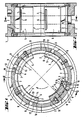
- the basic structure of the hydrodynamic radial slide bearing shown in FIGS. 1 to 3 consists of a bearing housing 1, a cylindrical tilting segment receptacle 2, a plurality of tilting segments 3 inserted into the tilting segment receptacle 2, distributed over their circumference, and a lubricant supply device 4.
- the tilting segments 3 have, on the shaft side, as usual, a sliding surface 5 with a lubricant supply transverse groove 6 on the edge 7 of the sliding surface 5 opposite the running direction of the shaft and on the rear side a tilting shape 8.
- the lubricant supply transverse grooves 6 are each provided with a lubricant supply opening 9 assigned.
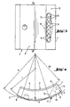
- the radial section of the tilting formation 8 corresponds to the section of a circle with a radius r that is reduced compared to the radius R of the cylindrical tilting segment receptacle 2. For this purpose, reference is also made to FIG. 4.
- This design leads to the tilting segments 3 forming a gap 10, 11 on both sides of the tilting formation 8 relative to the cylindrical tilting segment receptacle 2, which becomes wedge-shaped narrower in accordance with the tilting formation 8, that is to say in an outward radial projection under the tilting formation 8. 1 and 4, it can be seen that the gap spaces 10, 11 of the tilting segments 3 have an extension, namely a damping gap area 10, at least in the wedge-shaped area opposite the running direction of the shaft and formed by the tilting shape 8.
- This damping gap area 10 is formed, on the one hand, by a surface area of the cylindrical tilting segment receptacle 2, and, on the other hand, by a concentric back surface area 12 of the tilting segment 3, which is considered to be untilted.
- the arrangement is such that it has a segment channel 13 by means of the lubricant supply device 4, which is inclined from the lubricant supply transverse groove 6 obliquely to the tilting formation 8 and to an arranged lubricant supply opening 9 leads in the cylindrical tilting element holder 2.
- the damping gap area 10 opposite to the running direction of the shaft is several times longer than the area 11 lying in the running direction. It is understood that the damping gap areas 10, 11 in the figures are exaggerated for illustration reasons. In practice, the arrangement is generally such that the damping gap regions 10, 11, when the tilting segments 3 are not tilted, have a maximum gap thickness D which is approximately 2% of the sliding surface radius GR of the tilt segments 3.
- the supply of oil is ensured in the radial slide bearing described in that the segment channel 13 has a slot-shaped cross section extending over the width of the tilting segments 3 and runs out into a plurality of lubricant outlet bores 14.
- the lubricant outlet bores 14 open into the lubricant supply transverse groove 6. It goes without saying that the lubricant supply opening 9 is adapted to the cross section of the segment channel 13.
- the tilting segments 3 have a very large section modulus. In this respect, they are designed to be very rigid. This is achieved in that the tilting formations 8 and the tilting segment 3 each represent a single component.
Landscapes
- Engineering & Computer Science (AREA)
- General Engineering & Computer Science (AREA)
- Mechanical Engineering (AREA)
- Physics & Mathematics (AREA)
- Fluid Mechanics (AREA)
- Chemical & Material Sciences (AREA)
- Oil, Petroleum & Natural Gas (AREA)
- Sliding-Contact Bearings (AREA)
Abstract
Claims (5)
Priority Applications (1)
| Application Number | Priority Date | Filing Date | Title |
|---|---|---|---|
| AT87902409T ATE56507T1 (de) | 1986-05-23 | 1987-04-28 | Hydrodynamisches radialgleitlager. |
Applications Claiming Priority (2)
| Application Number | Priority Date | Filing Date | Title |
|---|---|---|---|
| DE3617289 | 1986-05-23 | ||
| DE19863617289 DE3617289A1 (de) | 1986-05-23 | 1986-05-23 | Hydrodynamisches radialgleitlager |
Publications (2)
| Publication Number | Publication Date |
|---|---|
| EP0269647A1 EP0269647A1 (fr) | 1988-06-08 |
| EP0269647B1 true EP0269647B1 (fr) | 1990-09-12 |
Family
ID=6301421
Family Applications (1)
| Application Number | Title | Priority Date | Filing Date |
|---|---|---|---|
| EP87902409A Expired - Lifetime EP0269647B1 (fr) | 1986-05-23 | 1987-04-28 | Palier a glissement radial hydrodynamique |
Country Status (5)
| Country | Link |
|---|---|
| US (1) | US4815865A (fr) |
| EP (1) | EP0269647B1 (fr) |
| BR (1) | BR8707312A (fr) |
| DE (2) | DE3617289A1 (fr) |
| WO (1) | WO1987007341A1 (fr) |
Families Citing this family (13)
| Publication number | Priority date | Publication date | Assignee | Title |
|---|---|---|---|---|
| US5288153A (en) * | 1993-01-04 | 1994-02-22 | Delaware Capital Formation, Inc. | Tilting pad journal bearing using directed lubrication |
| GB9400392D0 (en) * | 1994-01-11 | 1994-03-09 | Chester Keith I | Improved bearing assembly |
| US5720558A (en) * | 1995-10-16 | 1998-02-24 | Dresser-Rand Company | Tilting bearing pad with an axial feed groove having an exit side profiled area |
| US5759011A (en) * | 1996-05-14 | 1998-06-02 | Dresser-Rand Company | Journal bearing assembly |
| EP1890045A1 (fr) * | 2006-08-16 | 2008-02-20 | Siemens Aktiengesellschaft | paliers radiaux hydrodynamiques pour gros turbogénérateurs |
| US7780424B2 (en) * | 2008-10-21 | 2010-08-24 | Baker Hughes Incorporated | Self leveling dynamically stable radial bearing |
| US8342821B2 (en) | 2010-10-21 | 2013-01-01 | Baker Hughes Incorporated | Tuned bearing |
| US20140205224A1 (en) * | 2011-09-29 | 2014-07-24 | Hitachi, Ltd. | Direct Lubrication Tilting Pad Journal Bearing |
| DE102013223329A1 (de) * | 2013-11-15 | 2015-05-21 | Bosch Mahle Turbo Systems Gmbh & Co. Kg | Gasdynamisches Luftlager |
| TWI597436B (zh) * | 2016-03-15 | 2017-09-01 | 財團法人工業技術研究院 | 液靜壓軸承 |
| CN109312778B (zh) * | 2016-05-26 | 2020-12-01 | 弗兰德-格拉芬斯达登有限公司 | 具有注射器和偏转器的流体动力轴承 |
| WO2018029835A1 (fr) * | 2016-08-10 | 2018-02-15 | 三菱日立パワーシステムズ株式会社 | Ensemble palier et machine tournante |
| DE102020209611A1 (de) * | 2020-07-30 | 2022-02-03 | Siemens Energy Global GmbH & Co. KG | Hydrodynamisches Radial-Kippsegmentlager |
Family Cites Families (11)
| Publication number | Priority date | Publication date | Assignee | Title |
|---|---|---|---|---|
| US3023055A (en) * | 1960-03-14 | 1962-02-27 | Earl A Thompson | Pressure fed rocker shoe bearing |
| FR1450715A (fr) * | 1964-08-19 | 1966-06-24 | Escher Wyss Sa | Palier d'arbre avec rotor glissant sur des patins segmentaires orientables |
| US3351394A (en) * | 1965-01-07 | 1967-11-07 | Mechanical Tech Inc | Hydrostatic bearings for a rotatable element |
| FR1492819A (fr) * | 1965-12-28 | 1967-08-25 | Productions Ind Et De Distrib | Coussinet à coins d'huile auto-adaptés ou analogue et ses diverses applications |
| CH430344A (de) * | 1965-12-31 | 1967-02-15 | Bbc Brown Boveri & Cie | Radialgleitlager |
| US3589782A (en) * | 1969-09-18 | 1971-06-29 | Westinghouse Electric Corp | Damper bearing to increase rotor stability |
| CH569895A5 (fr) * | 1973-12-19 | 1975-11-28 | Maag Zahnraeder & Maschinen Ag | |
| DE3414910A1 (de) * | 1984-04-19 | 1985-10-24 | A. Friedr. Flender Gmbh & Co Kg, 4290 Bocholt | Kippsegment - gleitlager |
| CH665262A5 (de) * | 1984-06-22 | 1988-04-29 | Bbc Brown Boveri & Cie | Kippsegmentradiallager. |
| CH668811A5 (de) * | 1984-07-19 | 1989-01-31 | Glyco Metall Werke | Hydrodynamisches gleitlager. |
| US4568204A (en) * | 1984-09-04 | 1986-02-04 | Kingsbury, Inc. | Journal bearing |
-
1986
- 1986-05-23 DE DE19863617289 patent/DE3617289A1/de active Granted
-
1987
- 1987-04-28 WO PCT/DE1987/000187 patent/WO1987007341A1/fr active IP Right Grant
- 1987-04-28 EP EP87902409A patent/EP0269647B1/fr not_active Expired - Lifetime
- 1987-04-28 BR BR8707312A patent/BR8707312A/pt not_active IP Right Cessation
- 1987-04-28 US US07/137,019 patent/US4815865A/en not_active Expired - Fee Related
- 1987-04-28 DE DE8787902409T patent/DE3764931D1/de not_active Expired - Fee Related
Also Published As
| Publication number | Publication date |
|---|---|
| US4815865A (en) | 1989-03-28 |
| DE3764931D1 (de) | 1990-10-18 |
| DE3617289A1 (de) | 1987-11-26 |
| WO1987007341A1 (fr) | 1987-12-03 |
| DE3617289C2 (fr) | 1989-12-14 |
| EP0269647A1 (fr) | 1988-06-08 |
| BR8707312A (pt) | 1988-09-13 |
Similar Documents
| Publication | Publication Date | Title |
|---|---|---|
| EP0269647B1 (fr) | Palier a glissement radial hydrodynamique | |
| DE2939945C2 (fr) | ||
| EP1644647B1 (fr) | Palier lisse axial | |
| EP2140114B1 (fr) | Palier axial notamment pour un turbocompresseur | |
| DE69721336T2 (de) | Dynamisches gaslager mit folien | |
| EP1148965B1 (fr) | Lame de scie comportant des passages d'air allonges | |
| DE4440868C2 (de) | Temperatursensitive Ventilatorflüssigkeitsreibungskupplung | |
| EP0230885A1 (fr) | Turbosoufflante | |
| EP0158242A2 (fr) | Palier radial à contact lisse | |
| DE10334880A1 (de) | Anlaufscheibe für Planetengetriebe | |
| DE2622204A1 (de) | Formfolienlager | |
| DE2356817B2 (de) | Selbstdruckerzeugendes Radialgleitlager | |
| EP0476395A2 (fr) | Disposition des disques de support axial pour des satellites dans un porte-satellites | |
| DE2838768B2 (de) | Mehrflächengleitlager | |
| DE3327119A1 (de) | Luftlageranordnung fuer ein zahnaerztliches handstueck | |
| DE4019699C2 (fr) | ||
| DE19804734A1 (de) | Planetenscheibe | |
| DE3905450C2 (de) | Gleitlager | |
| EP0287847B1 (fr) | Outil de coupe | |
| CH677009A5 (fr) | ||
| EP1266128A1 (fr) | Structure de rigidification et de refroidissement d'une aube de turbine | |
| DE3001061C2 (fr) | ||
| CH626959A5 (fr) | ||
| DE102016103396A1 (de) | Bremsbelag einer Scheibenbremse und Bremsbelagsatz | |
| DE8424844U1 (de) | Flanschlager |
Legal Events
| Date | Code | Title | Description |
|---|---|---|---|
| PUAI | Public reference made under article 153(3) epc to a published international application that has entered the european phase |
Free format text: ORIGINAL CODE: 0009012 |
|
| 17P | Request for examination filed |
Effective date: 19880217 |
|
| AK | Designated contracting states |
Kind code of ref document: A1 Designated state(s): AT BE CH DE FR GB IT LI NL SE |
|
| 17Q | First examination report despatched |
Effective date: 19890623 |
|
| RBV | Designated contracting states (corrected) |
Designated state(s): AT BE CH DE FR GB IT LI SE |
|
| ITF | It: translation for a ep patent filed |
Owner name: DE DOMINICIS & MAYER S.R.L. |
|
| GRAA | (expected) grant |
Free format text: ORIGINAL CODE: 0009210 |
|
| AK | Designated contracting states |
Kind code of ref document: B1 Designated state(s): AT BE CH DE FR GB IT LI SE |
|
| REF | Corresponds to: |
Ref document number: 56507 Country of ref document: AT Date of ref document: 19900915 Kind code of ref document: T |
|
| REF | Corresponds to: |
Ref document number: 3764931 Country of ref document: DE Date of ref document: 19901018 |
|
| ET | Fr: translation filed | ||
| GBT | Gb: translation of ep patent filed (gb section 77(6)(a)/1977) | ||
| ITTA | It: last paid annual fee | ||
| PLBE | No opposition filed within time limit |
Free format text: ORIGINAL CODE: 0009261 |
|
| STAA | Information on the status of an ep patent application or granted ep patent |
Free format text: STATUS: NO OPPOSITION FILED WITHIN TIME LIMIT |
|
| 26N | No opposition filed | ||
| PGFP | Annual fee paid to national office [announced via postgrant information from national office to epo] |
Ref country code: DE Payment date: 19940223 Year of fee payment: 8 |
|
| PGFP | Annual fee paid to national office [announced via postgrant information from national office to epo] |
Ref country code: SE Payment date: 19940321 Year of fee payment: 8 |
|
| PGFP | Annual fee paid to national office [announced via postgrant information from national office to epo] |
Ref country code: FR Payment date: 19940323 Year of fee payment: 8 |
|
| PGFP | Annual fee paid to national office [announced via postgrant information from national office to epo] |
Ref country code: BE Payment date: 19940415 Year of fee payment: 8 |
|
| PGFP | Annual fee paid to national office [announced via postgrant information from national office to epo] |
Ref country code: CH Payment date: 19940425 Year of fee payment: 8 |
|
| PGFP | Annual fee paid to national office [announced via postgrant information from national office to epo] |
Ref country code: AT Payment date: 19940429 Year of fee payment: 8 |
|
| EAL | Se: european patent in force in sweden |
Ref document number: 87902409.9 |
|
| PGFP | Annual fee paid to national office [announced via postgrant information from national office to epo] |
Ref country code: GB Payment date: 19950216 Year of fee payment: 9 |
|
| PG25 | Lapsed in a contracting state [announced via postgrant information from national office to epo] |
Ref country code: AT Effective date: 19950428 |
|
| PG25 | Lapsed in a contracting state [announced via postgrant information from national office to epo] |
Ref country code: SE Effective date: 19950429 |
|
| PG25 | Lapsed in a contracting state [announced via postgrant information from national office to epo] |
Ref country code: LI Effective date: 19950430 Ref country code: CH Effective date: 19950430 Ref country code: BE Effective date: 19950430 |
|
| BERE | Be: lapsed |
Owner name: BRAUNSCHWEIGER HUTTENWERK G.M.B.H. Effective date: 19950430 |
|
| REG | Reference to a national code |
Ref country code: CH Ref legal event code: PL |
|
| PG25 | Lapsed in a contracting state [announced via postgrant information from national office to epo] |
Ref country code: FR Effective date: 19951229 |
|
| PG25 | Lapsed in a contracting state [announced via postgrant information from national office to epo] |
Ref country code: DE Effective date: 19960103 |
|
| EUG | Se: european patent has lapsed |
Ref document number: 87902409.9 |
|
| REG | Reference to a national code |
Ref country code: FR Ref legal event code: ST |
|
| PG25 | Lapsed in a contracting state [announced via postgrant information from national office to epo] |
Ref country code: GB Effective date: 19960428 |
|
| GBPC | Gb: european patent ceased through non-payment of renewal fee |
Effective date: 19960428 |
|
| PG25 | Lapsed in a contracting state [announced via postgrant information from national office to epo] |
Ref country code: IT Free format text: LAPSE BECAUSE OF NON-PAYMENT OF DUE FEES Effective date: 20050428 |