EP0269647B1 - Hydrodynamic radial sliding bearing - Google Patents
Hydrodynamic radial sliding bearing Download PDFInfo
- Publication number
- EP0269647B1 EP0269647B1 EP87902409A EP87902409A EP0269647B1 EP 0269647 B1 EP0269647 B1 EP 0269647B1 EP 87902409 A EP87902409 A EP 87902409A EP 87902409 A EP87902409 A EP 87902409A EP 0269647 B1 EP0269647 B1 EP 0269647B1
- Authority
- EP
- European Patent Office
- Prior art keywords
- tilting
- segments
- segment
- sliding bearing
- shaft
- Prior art date
- Legal status (The legal status is an assumption and is not a legal conclusion. Google has not performed a legal analysis and makes no representation as to the accuracy of the status listed.)
- Expired - Lifetime
Links
Images
Classifications
-
- F—MECHANICAL ENGINEERING; LIGHTING; HEATING; WEAPONS; BLASTING
- F16—ENGINEERING ELEMENTS AND UNITS; GENERAL MEASURES FOR PRODUCING AND MAINTAINING EFFECTIVE FUNCTIONING OF MACHINES OR INSTALLATIONS; THERMAL INSULATION IN GENERAL
- F16C—SHAFTS; FLEXIBLE SHAFTS; ELEMENTS OR CRANKSHAFT MECHANISMS; ROTARY BODIES OTHER THAN GEARING ELEMENTS; BEARINGS
- F16C17/00—Sliding-contact bearings for exclusively rotary movement
- F16C17/02—Sliding-contact bearings for exclusively rotary movement for radial load only
- F16C17/03—Sliding-contact bearings for exclusively rotary movement for radial load only with tiltably-supported segments, e.g. Michell bearings
-
- F—MECHANICAL ENGINEERING; LIGHTING; HEATING; WEAPONS; BLASTING
- F16—ENGINEERING ELEMENTS AND UNITS; GENERAL MEASURES FOR PRODUCING AND MAINTAINING EFFECTIVE FUNCTIONING OF MACHINES OR INSTALLATIONS; THERMAL INSULATION IN GENERAL
- F16C—SHAFTS; FLEXIBLE SHAFTS; ELEMENTS OR CRANKSHAFT MECHANISMS; ROTARY BODIES OTHER THAN GEARING ELEMENTS; BEARINGS
- F16C33/00—Parts of bearings; Special methods for making bearings or parts thereof
- F16C33/02—Parts of sliding-contact bearings
- F16C33/04—Brasses; Bushes; Linings
- F16C33/06—Sliding surface mainly made of metal
- F16C33/10—Construction relative to lubrication
- F16C33/1025—Construction relative to lubrication with liquid, e.g. oil, as lubricant
- F16C33/1045—Details of supply of the liquid to the bearing
Definitions
- the invention relates generically to a hydrodynamic radial plain bearing, - with bearing housing, cylindrical tilting segment receptacle, inserted into the tilting segment receptacle, tilt segments distributed over its circumference and lubricant supply device with lubricant supply openings in the tilting segment receptacle, the tilting segments on the shaft side having a sliding surface with lubricant supply direction transverse to the shaft Edge of their sliding surface and on the back have a tilting shape, the radial section of which corresponds to the cutout of a circle with a radius that is reduced compared to the radius of the cylindrical tilting segment receptacle, wherein the tilting segments on both sides of the tilting shape form a gap with respect to the cylindrical tilting segment receptacle, which according to the tilting shape, ie in a radially outward projection, as it were, under the tilt formation, can extend over the entire width of the individual tilt segments or can be arranged only in regions, for example in the central region of the width of the
- Such a radial slide bearing must on the one hand master the shaft dynamics or the dynamics of a rotor connected to the shaft and on the other hand work with little loss.
- the wave dynamics include the vibration amplitudes of the shaft and / or the rotor which are associated with the bending vibration or the critical speeds. It is important to dampen these vibrations.
- the losses result from the lubricant friction not only in the sliding gaps that form the sliding surfaces of the tilting segments with the surface of the shaft, but also in the spaces between the tilting segments.
- the gaps on the segment back are wedge-shaped over their entire length in the manner described.
- the lubricant supply channels run more or less radially in the tilting segments and are located in the area of the segment support. From there, the lubricant is fed to the lubrication gaps.
- lubricant escapes through the gap spaces, which lubricant hardly contributes to damping the vibrations described at the beginning.
- the damping takes place practically exclusively in the lubricant layer and is in need of improvement in the case of generic radial plain bearings.
- the lubricant gets into the space between the tilting segments and, due to turbulence and the resulting internal friction, contributes considerably to power loss and oil loss.
- the invention has for its object to further develop a generic radial slide bearing so that without additional components, a very pronounced damping of the vibrations described takes place and the oil losses and power loss are reduced.
- the invention teaches that the gap spaces of the tilting segments have an extension, namely a damping gap area, at least on the wedge-shaped areas formed by the tilting shape opposite the running direction of the shaft, which on the one hand has a surface area of the cylindrical tilting segment receptacle and on the other hand a concentric back surface area of the tilting segment is formed, and that the lubricant supply device has a segment channel which leads obliquely from the lubricant supply transverse groove to the tilting shape and to the associated lubricant supply opening arranged there in the tilting segment receptacle.
- the invention is based on the knowledge that the gap spaces under the tilting segments can make a significant contribution to reducing oil losses and power loss as well as to damping vibrations if they have areas that are not wedge-shaped, but are designed as damping gap areas with a small gap thickness. This is achieved if damping gap areas are formed, which are formed on the one hand by a surface area of the cylindrical tilting segment receptacle, on the other hand by a concentric back surface area of the tilting segment that is not tilted, and if care is taken to ensure that this damping gap area is also sufficiently long.
- the lubricant supply device has the described, inclined segment channels, so that no lubricant can penetrate into the tilting segment spaces.
- the thickness of the damping gap areas and their length must be adapted to the special conditions, taking into account the degree of freedom of tilting of the tilting segments.
- the thickness of the damping gap regions will be made as small as possible, on the other hand the damping gap regions will extend in the circumferential direction as long as possible.
- a preferred and proven embodiment of the invention with damping gap regions arranged on both sides of the wedge-shaped regions formed by the tilting segment shape is characterized in that the damping gap region opposite the direction of travel of the shaft is several times longer than the region lying in the running direction, because this region is to a greater extent than the area lying in the running direction can contribute to damping the described vibrations.
- the damping gap areas in the case of untilted tilting segments, are designed as parallel gaps and have a gap thickness of a maximum of 2%, preferably less than 1 %, of the sliding surface radius of the tilting segments.
- the invention recommends that the segment channel have a slot-shaped cross section that extends across the width of the tilting segments and that they run into a plurality of lubricant outlet bores that open into the lubricant supply transverse groove, and that the lubricant supply opening is adapted to the cross section of the segment channel.
- the tilting segments are subjected to considerable mechanical loads. This also includes bending moments with a bending moment axis that coincides more or less with the radial slide bearing axis.
- a preferred embodiment of the invention is of independent importance (in combination with the other features discussed above) that the tilt formation and the tilt segment are each formed as a single component.
- the tilting segments constructed in this way have a very large section modulus in relation to the mechanical loads to be absorbed and consequently also a corresponding bending stiffness.
- the tilting formation can also be formed in a manner known per se on a special component which is inserted into a corresponding receptacle in the back of the tilting segments.
- the end face of the bearing housing is open, so that the lubricant can flow away as usual.
- the requirement for good tilting mobility of the tilting segments on the one hand and for a small gap height in the region of the oil transfer from the bearing housing to the tilting segments is met.
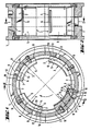
- the basic structure of the hydrodynamic radial slide bearing shown in FIGS. 1 to 3 consists of a bearing housing 1, a cylindrical tilting segment receptacle 2, a plurality of tilting segments 3 inserted into the tilting segment receptacle 2, distributed over their circumference, and a lubricant supply device 4.
- the tilting segments 3 have, on the shaft side, as usual, a sliding surface 5 with a lubricant supply transverse groove 6 on the edge 7 of the sliding surface 5 opposite the running direction of the shaft and on the rear side a tilting shape 8.
- the lubricant supply transverse grooves 6 are each provided with a lubricant supply opening 9 assigned.
- the radial section of the tilting formation 8 corresponds to the section of a circle with a radius r that is reduced compared to the radius R of the cylindrical tilting segment receptacle 2. For this purpose, reference is also made to FIG. 4.
- This design leads to the tilting segments 3 forming a gap 10, 11 on both sides of the tilting formation 8 relative to the cylindrical tilting segment receptacle 2, which becomes wedge-shaped narrower in accordance with the tilting formation 8, that is to say in an outward radial projection under the tilting formation 8. 1 and 4, it can be seen that the gap spaces 10, 11 of the tilting segments 3 have an extension, namely a damping gap area 10, at least in the wedge-shaped area opposite the running direction of the shaft and formed by the tilting shape 8.
- This damping gap area 10 is formed, on the one hand, by a surface area of the cylindrical tilting segment receptacle 2, and, on the other hand, by a concentric back surface area 12 of the tilting segment 3, which is considered to be untilted.
- the arrangement is such that it has a segment channel 13 by means of the lubricant supply device 4, which is inclined from the lubricant supply transverse groove 6 obliquely to the tilting formation 8 and to an arranged lubricant supply opening 9 leads in the cylindrical tilting element holder 2.
- the damping gap area 10 opposite to the running direction of the shaft is several times longer than the area 11 lying in the running direction. It is understood that the damping gap areas 10, 11 in the figures are exaggerated for illustration reasons. In practice, the arrangement is generally such that the damping gap regions 10, 11, when the tilting segments 3 are not tilted, have a maximum gap thickness D which is approximately 2% of the sliding surface radius GR of the tilt segments 3.
- the supply of oil is ensured in the radial slide bearing described in that the segment channel 13 has a slot-shaped cross section extending over the width of the tilting segments 3 and runs out into a plurality of lubricant outlet bores 14.
- the lubricant outlet bores 14 open into the lubricant supply transverse groove 6. It goes without saying that the lubricant supply opening 9 is adapted to the cross section of the segment channel 13.
- the tilting segments 3 have a very large section modulus. In this respect, they are designed to be very rigid. This is achieved in that the tilting formations 8 and the tilting segment 3 each represent a single component.
Abstract
Description
Die Erfindung bezieht sich gattungsgemäß auf ein hydrodynamisches Radialgleitlager, - mit Lagergehäuse, zylindrischer Kippsegmentaufnahme, in die Kippsegmentaufnahme eingesetzten, über deren Umfang verteilten Kippsegmenten und Schmiermittelzuführungseinrichtung mit Schmiermittelzuführungsöffnungen in der Kippsegmentaufnahme, wobei die Kippsegmente wellenseitig eine Gleitfläche mit Schmiermittelzuführungsquernut an dem der Laufrichtung der Welle entgegengesetzten Rand ihrer Gleitfläche und rückseitig eine Kippausformung aufweisen, deren Radialschnitt dem Ausschnitt eines Kreises mit gegenüber dem Radius der zylinderischen Kippsegmentaufnahme reduziertem Radius entspricht, wobei außerdem die Kippsegmente beidseits der Kippausformung gegenüber der zylindrischen Kippsegmentaufnahme einen Spaltraum bilden, der nach Maßgabe der Kippausformung, d.h. in einer radial nach außen gerichteten Projektion gleichsam unter der Kippausformung sich über die gesamte Breite der einzelnen Kippsegmente erstrecken kann oder nur bereichsweise, beispielsweise im mittleren Bereich der Breite der Kippsegmente, angeordnet sein kann. - Ein solches Radialgleitlager muß einerseits die Wellendynamik bzw. die Dynamik eines mit der Welle verbundenen Rotors beherrschen und andererseits verlustarm arbeiten. Zur Wellendynamik gehören die mit der Biegeschwingung bzw. den kritischen Drehzahlen verbundenen Schwingungsamplituden der Welle und/oder des Rotors. Diese Schwingungserscheinungen gilt es zu dämpfen. Die Verluste resultieren aus der Schmiermittelreibung nicht nur in den Gleitspalten, die die Gleitflächen der Kippsegmente mit der Oberfläche der Welle bilden, sondern auch in den Kippsegmentzwischenräumen.The invention relates generically to a hydrodynamic radial plain bearing, - with bearing housing, cylindrical tilting segment receptacle, inserted into the tilting segment receptacle, tilt segments distributed over its circumference and lubricant supply device with lubricant supply openings in the tilting segment receptacle, the tilting segments on the shaft side having a sliding surface with lubricant supply direction transverse to the shaft Edge of their sliding surface and on the back have a tilting shape, the radial section of which corresponds to the cutout of a circle with a radius that is reduced compared to the radius of the cylindrical tilting segment receptacle, wherein the tilting segments on both sides of the tilting shape form a gap with respect to the cylindrical tilting segment receptacle, which according to the tilting shape, ie in a radially outward projection, as it were, under the tilt formation, can extend over the entire width of the individual tilt segments or can be arranged only in regions, for example in the central region of the width of the tilt segments. - Such a radial slide bearing must on the one hand master the shaft dynamics or the dynamics of a rotor connected to the shaft and on the other hand work with little loss. The wave dynamics include the vibration amplitudes of the shaft and / or the rotor which are associated with the bending vibration or the critical speeds. It is important to dampen these vibrations. The losses result from the lubricant friction not only in the sliding gaps that form the sliding surfaces of the tilting segments with the surface of the shaft, but also in the spaces between the tilting segments.
Bei der bekannten gattungsgemäßen Ausführungsform (DE-A-3 414 910) sind die Spalte am Segmentrücken über ihre gesamte Länge in der beschriebenen Weise keilförmig. Die Schmiermittelzuführungskanäle verlaufen in den Kippsegmenten mehr oder weniger radial und befinden sich im Bereich der Segmentabstützung. Von dort aus wird das Schmiermittel den Schmierspalten zugeführt. Das hat zur Folge, daß bei arbeitendem Radialgleitlager über die Spalträume Schmiermittel austritt, welches in den Spalträumen zur Dämpfung der eingangs beschriebenen Schwingungen kaum beiträgt. Die Dämpfung erfolgt praktisch ausschließlich in der Schmiermittelschicht und ist bei gattungsgemäßen Radialgleitlagern verbesserungsbedürftig. Das Schmiermittel gelangt in die Kippsegmentzwischenräume und trägt durch Verwirbelung und dadurch bedingter innerer Reibung in erheblichem Maße zu einerseits Verlustleistung, andererseits Ölverlusten bei.In the known generic embodiment (DE-A-3 414 910), the gaps on the segment back are wedge-shaped over their entire length in the manner described. The lubricant supply channels run more or less radially in the tilting segments and are located in the area of the segment support. From there, the lubricant is fed to the lubrication gaps. As a result, when the radial plain bearing is working, lubricant escapes through the gap spaces, which lubricant hardly contributes to damping the vibrations described at the beginning. The damping takes place practically exclusively in the lubricant layer and is in need of improvement in the case of generic radial plain bearings. The lubricant gets into the space between the tilting segments and, due to turbulence and the resulting internal friction, contributes considerably to power loss and oil loss.
Der Erfindung liegt die Aufgabe zugrunde, ein gattungsgemäßes Radialgleitlager so weiter auszubilden, daß ohne zusätzliche Bauteile eine sehr ausgeprägte Dämpfung der beschriebenen Schwingungen erfolgt und die Ölverluste sowie Verlustleistung reduziert werden.The invention has for its object to further develop a generic radial slide bearing so that without additional components, a very pronounced damping of the vibrations described takes place and the oil losses and power loss are reduced.
Zur Lösung dieser Aufgabe lehrtdie Erfindung, daß die Spalträume der Kippsegmente zumindest an dem der Laufrichtung der Welle entgegengesetzten keilförmigen, durch die Kippausformung gebildeten Bereichen eine Verlängerung, nämlich einen Dämpfungsspaltbereich aufweisen, der einerseits durch einen Flächenbereich der zylindrischen Kippsegmentaufnahme, andererseits durch einen dazu konzentrischen Rückenflächenbereich des Kippsegmentes gebildet ist, und daß die Schmiermittelzuführungseinrichtung einen Segmentkanal aufweist, der von der Schmiermittelzuführungsquernut schräg zur Kippausformung und zu der dort angeordneten, zugeordneten Schmiermittelzuführungsöffnung in der Kippsegmentaufnahme führt. - Die Erfindung geht von der Erkenntnis aus, daß die Spalträume unter den Kippsegmenten in erheblichem Maße zur Reduzierung der Ölverluste und Verlustleistung sowie zur Schwingungsdämpfung beitragen können, wenn Sie Bereiche aufweisen, die nicht keilförmig erweitert, sondern als Dämpfungsspaltbereiche geringer Spaltdicke ausgeführt sind. Das erreicht man, wenn man Dämpfungsspaltbereiche bildet, die einerseits durch einen Flächenbereich der zylindrischen Kippsegmentaufnahme, andererseits durch einen dazu konzentrischen Rückenflächenbereich des ungekippt betrachteten Kippsegmentes gebildet sind und wenn man dafür Sorge trägt, daß außerdem dieser Dämpfungsspaltbereich hinreichend lang ist. Dazu gehört, daß die Schmiermittelzuführungseinrichtung die beschriebenen, schräg geführten Segmentkanäle aufweist, so daß in die Kippsegmentzwischenräume kein Schmiermittel eindringen kann. Es versteht sich, daß man die Dicke der Dämpfungsspaltbereiche und deren Länge den speziellen Verhältnissen anpassen muß, wobei auf den Kippfreiheitsgrad der Kippsegmente Rücksicht zu nehmen ist. Man wird die Dicke der Dämpfungsspaltbereiche so gering wie möglich machen, andererseits die Dämpfungsspaltbereiche in Umfangsrichtung so lang wie möglich erstrecken. Eine bevorzugte und bewährte Ausführungsform der Erfindung mit beidseits der keilförmigen, durch die Kippsegmentausformung gebildeten Bereiche angeordneten, Dämpfungsspaltbereichen ist dadurch gekennzeichnet, daß der der Laufrichtung der Welle entgegengesetzte Dämpfungsspaltbereich um ein Mehrfaches länger ist als der in Laufrichtung liegende Bereich, weil dieser Bereich in stärkerem Maße als der in Laufrichtung liegende Bereich zur Dämpfung der beschriebenen Schwingungen beitragen kann. Handelt es sich um Radialgleitlager mit einem Radius von 5 bis 10 cm, so empfiehlt es sich die Auslegung so zu treffen, daß die Dämpfungsspaltbereiche, bei ungekippten Kippsegmenten als Parallelspalte ausgebildet sind und eine Spaltdicke aufweisen, die maximal von 2 %, vorzugsweise weniger als 1 %, vom Gleitflächenradius der Kippsegmente ausmacht. Damit die Schmiermittelzuführung den bei erfindungsgemäßen Radialgleitlagern auftretenden Anforderungen genügt, empfiehlt die Erfindung, daß der Segmentkanal einen über die Breite der Kippsegmente erstreckten schlitzförmigen Querschnitt aufweist und in eine Mehrzahl von Schmiermittelaustrittsbohrungen ausläuft, die in die Schmiermittelzuführungsquernut einmünden, und daß die Schmiermittelzuführungsöffnung dem Querschnitt des Segmentkanals angepaßt ist.To achieve this object, the invention teaches that the gap spaces of the tilting segments have an extension, namely a damping gap area, at least on the wedge-shaped areas formed by the tilting shape opposite the running direction of the shaft, which on the one hand has a surface area of the cylindrical tilting segment receptacle and on the other hand a concentric back surface area of the tilting segment is formed, and that the lubricant supply device has a segment channel which leads obliquely from the lubricant supply transverse groove to the tilting shape and to the associated lubricant supply opening arranged there in the tilting segment receptacle. - The invention is based on the knowledge that the gap spaces under the tilting segments can make a significant contribution to reducing oil losses and power loss as well as to damping vibrations if they have areas that are not wedge-shaped, but are designed as damping gap areas with a small gap thickness. This is achieved if damping gap areas are formed, which are formed on the one hand by a surface area of the cylindrical tilting segment receptacle, on the other hand by a concentric back surface area of the tilting segment that is not tilted, and if care is taken to ensure that this damping gap area is also sufficiently long. This includes that the lubricant supply device has the described, inclined segment channels, so that no lubricant can penetrate into the tilting segment spaces. It goes without saying that the thickness of the damping gap areas and their length must be adapted to the special conditions, taking into account the degree of freedom of tilting of the tilting segments. The thickness of the damping gap regions will be made as small as possible, on the other hand the damping gap regions will extend in the circumferential direction as long as possible. A preferred and proven embodiment of the invention with damping gap regions arranged on both sides of the wedge-shaped regions formed by the tilting segment shape is characterized in that the damping gap region opposite the direction of travel of the shaft is several times longer than the region lying in the running direction, because this region is to a greater extent than the area lying in the running direction can contribute to damping the described vibrations. If radial slide bearings with a radius of 5 to 10 cm are involved, it is advisable to design them so that the damping gap areas, in the case of untilted tilting segments, are designed as parallel gaps and have a gap thickness of a maximum of 2%, preferably less than 1 %, of the sliding surface radius of the tilting segments. So that the lubricant supply In the case of requirements that arise in the case of radial plain bearings according to the invention, the invention recommends that the segment channel have a slot-shaped cross section that extends across the width of the tilting segments and that they run into a plurality of lubricant outlet bores that open into the lubricant supply transverse groove, and that the lubricant supply opening is adapted to the cross section of the segment channel.
Bei einem hydrodynamischen Radialgleitlager des beschriebenen Aufbaus erfahren die Kippsegmente erhebliche mechanische Beanspruchungen. Dazu gehören auch Biegemomente mit einer mehr oder weniger mit der Radialgleitlagerachse zusammenfallenden Biegemomentachse. Um nichtsdestoweniger sicherzustellen, daß das Radialgleitlager mit definierten Verhältnissen in bezug auf die Dämpfungsspaltbereiche und in bezug auf die Schmiermittelschicht auf den Gleitflächen arbeitet, ist eine bevorzugte Ausführungsform der Erfindung, der selbständige Bedeutung zukommt (in Kombination zu den übrigen, vorstehend behandelten Merkmalen) dadurch gekennzeichnet, daß die Kippausformung und das Kippsegment jeweils als einheitliches Bauteil geformt sind. Die so aufgebauten Kippsegmente haben in bezug auf die aufzunehmenden mechanischen Beanspruchungen ein sehr großes Widerstandsmoment und folglich auch eine entsprechende Biegesteifigkeit. Hinzu kommt, daß in diesem Fall auf den Einsatz zusätzlicher Bauteile verzichtet wird. Dadurch lassen sich besonders kleine Lager mit einer direkten Schmiermittelüberleitung verwirklichen. Wo die mechanischen Beanspruchungen weniger groß sind, kann aber auch in an sich bekannter Weise die Kippausformung an einem besonderen Bauteil ausgeformt sein, welches in eine entsprechende Aufnahme im Rücken der Kippsegmente eingesetzt ist.In the case of a hydrodynamic radial sliding bearing of the construction described, the tilting segments are subjected to considerable mechanical loads. This also includes bending moments with a bending moment axis that coincides more or less with the radial slide bearing axis. In order to ensure nonetheless that the radial slide bearing operates with defined ratios in relation to the damping gap areas and in relation to the lubricant layer on the sliding surfaces, a preferred embodiment of the invention is of independent importance (in combination with the other features discussed above) that the tilt formation and the tilt segment are each formed as a single component. The tilting segments constructed in this way have a very large section modulus in relation to the mechanical loads to be absorbed and consequently also a corresponding bending stiffness. In addition, the use of additional components is dispensed with in this case. This makes it possible to realize particularly small bearings with direct lubricant transfer. Where the mechanical stresses are less great, the tilting formation can also be formed in a manner known per se on a special component which is inserted into a corresponding receptacle in the back of the tilting segments.
Die erreichten Vorteile sind darin zu sehen, daß bei einem erfindungsgemäßen Radialgleitlager eine sehr ausgeprägte Dämpfung der eingangs beschriebenen Schwingungen erreicht wird, weil diese Dämpfung nicht nur in der Schmiermittelschicht über der Gleitfläche, sondern auch in den Spalträumen unter den Kippsegmenten erfolgt, die entsprechend ausgebildet sind. Hinzu kommt, daß bei dieser Ausbildung der Spalträume zu Dämpfungsspaltbereichen der Schmiermittelaustritt über die Dämpfungsspaltbereiche reduziert wird, so daß die Ölmenge, die sich in den Kippsegmentzwischenräumen ansammelt, verhältnismäßig gering ist und zu den vorstehend beschriebenen Verlusten praktisch nicht mehr beiträgt. Folglich wurden die Ölverluste und die Verlustleistung reduziert. Das erfindungsgemäße Radialgleitlager arbeitet daher in beachtlichem Maße verlustarm. Es versteht sich, daß das Lagergehäuse stirnseitig offen ist, so daß das Schmiermittel wie üblich abfließen kann. Darüber hinaus ist die Forderung nach guter Kippbeweglichkeit der Kippsegmente einerseits und nach geringer Spalthöhe im Bereich des Ölübertritts vom Lagergehäuse zu den Kippsegmenten erfüllt.The advantages achieved can be seen in the fact that, in a radial slide bearing according to the invention, a very pronounced damping of the vibrations described at the outset is achieved, because this damping takes place not only in the lubricant layer above the sliding surface, but also in the gap spaces under the tilting segments, which are designed accordingly . In addition, with this configuration of the gap spaces to damping gap areas, the lubricant leakage through the damping gap areas is reduced, so that the amount of oil that accumulates in the tilting segment spaces is relatively small and practically no longer contributes to the losses described above. As a result, oil losses and power loss have been reduced. The radial sliding bearing according to the invention therefore operates with a low loss. It goes without saying that the end face of the bearing housing is open, so that the lubricant can flow away as usual. In addition, the requirement for good tilting mobility of the tilting segments on the one hand and for a small gap height in the region of the oil transfer from the bearing housing to the tilting segments is met.
Im folgenden wird die Erfindung anhand einer lediglich ein Ausführungsbeispiel darstellenden Zeichnung ausführlicher erläutert. Es zeigen in schematischer Darstellung
- Fig. 1 einen orthogonal zur Achse geführten Schnitt durch ein erfindungsgemäßes Radialgleitlager,
- Fig. 2 einen Querschnitt durch den Gegenstand nach Fig. 1,
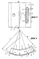
- Fig. 3 eine Ansicht des Kippsegmentes aus dem Gegenstand nach Fig. 1 aus Richtung des pfeiles A ausschnittsweise und
- Fig. 4 in gegenüber den Fig. 1 bis 3 wesentlich vergrößertem Maßstab die Ansicht eines Kippsegmentes aus einem erfindungsgemäßen Radialgleitlager.
- 1 is a section perpendicular to the axis through a radial slide bearing according to the invention,
- 2 shows a cross section through the object according to FIG. 1,
- Fig. 3 is a partial view of the tilting segment from the object according to Fig. 1 from the direction of arrow A and
- Fig. 4 in a significantly enlarged scale compared to FIGS. 1 to 3, the view of a tilting segment from a radial slide bearing according to the invention.
Das in den Figuren 1 bis 3 dargestellte hydrodynamische Radialgleitlager besteht in seinem grundsätzlichen Aufbau aus einem Lagergehäuse 1 einer zylindrischen Kippsegmentaufnahme 2, einer Mehrzahl von in die Kippsegmentaufnahme 2 eingesetzten, über deren Umfang verteilten Kippsegmenten 3 und einer Schmiermittelzuführungseinrichtung 4.The basic structure of the hydrodynamic radial slide bearing shown in FIGS. 1 to 3 consists of a bearing housing 1, a cylindrical
Die Kippsegmente 3 besitzen wellenseitig, wie üblich, eine Gleitfläche 5 mit Schmiermittelzuführungsquernut 6 an dem der Laufrichtung der Welle entgegengesetzten Rand 7 der Gleitfläche 5 und rückenseitig eine Kippausformung 8. Wie insbesondere die Fig. 1 erkennen läßt, ist den Schmiermittelzuführungsquernuten 6 jeweils eine Schmiermittelzuführungsöffnung 9 zugeordnet. Der Radialschnitt der Kippausformung 8 entspricht dem Ausschnitt eines Kreises mit gegenüber dem Radius R der zylindrischen Kippsegmentaufnahme 2 reduziertem Radius r. Dazu wird auch auf die Figur 4 verwiesen. Diese Gestaltung führt dazu, daß die Kippsegmente 3 beidseits der Kippausformung 8 gegenüber der zylindrischen Kippsegmentaufnahme 2 einen Spaltraum 10, 11 bilden, der nach Maßgabe der Kippausformung 8, d.h. in einer nach außen gerichteten radialen Projektion gleichsam unter der Kippausformung 8, keilförmig enger wird. Aus einer vergleichenden Betrachtung der Fig. 1 und 4 entnimmt man, daß die Spalträume 10, 11 der Kippsegmente 3 zumindest an dem der Laufrichtung der Welle entgegengesetzten keilförmigen, durch die Kippausformung 8 gebildeten Bereich eine Verlängerung, nämlich einen Dämpfungsspaltbereich 10 aufweisen. Dieser Dämpfungsspaltbereich 10 ist einerseits durch einen Flächenbereich ser zylindrischen Kippsegmentaufnahme 2, andererseits durch einen dazu konzentrischen Rückenflächenbereich 12 des insoweit ungekippt betrachteten Kippsegmentes 3 gebildet. Damit der Strömungsweg des Schmiermittels in diesen Dämpfungsspaltbereichen 10 möglichst lang ist, wie die Figur 1 zeigt, ist die Anordnung so getroffen, daß sie mittels Schmiermittelzuführungseinrichtung 4 einen Segmentkanal 13 aufweist, der von der Schmiermittelzuführungsquernut 6 schräg zur Kippausformung 8 und zu einer angeordneten Schmiermittelzuführungsöffnung 9 in der zylindrischen Kippsementaufnahme 2 führt. In Figur 1 wurde dargestellt, daß der der Laufrichtung der Welle entgegengesetzte Dämpfungsspaltbereich 10 um ein Mehrfaches länger ist als der in Laufrichtung liegende Bereich 11. Es versteht sich, daß die Dämpfungsspaltbereiche 10, 11 in den Figuren aus darstellungstechnischen Gründen übertrieben groß gezeichnet sind. In der Praxis ist die Anordnung im allgemeinen so getroffen, daß die Dämpfungsspaltbereiche 10, 11 bei ungekippten Kippsegmenten 3 betrachtet, eine maximale Spaltdicke D aufweisen, die etwa 2 % vom Gleitflächenradius GR der Kippsegmente 3 ausmacht.The
Die Ölzuführung ist bei dem beschriebenen Radialgleitlager dadurch sichergestellt, daß der Segmentkanal 13 einen über die Breite der Kippsegmente 3 erstreckten schlitzförmigen Querschnitt aufweist und in eine Mehrzahl von Schmiermittelaustrittsbohrungen 14 ausläuft. Dazu wird insbesondere auf die Figur 3 verwiesen. Die Schmiermittelaustrittsbohrungen 14 münden in der Schmiermittelzuführungsquernut 6. Es versteht sich, daß die Schmiermittelzuführungsöffnung 9 dem Querschnitt des Segmentkanals 13 angepaßt ist.The supply of oil is ensured in the radial slide bearing described in that the
Bei der dargestellten Ausführungsform besitzen die Kippsegmente 3 ein sehr großes Widerstandsmoment. Sie sind insoweit sehr biegesteif gestaltet. Das erreicht man dadurch, daß die Kippausformungen 8 und das Kippsegment 3 jeweils ein einheitliches Bauteil darstellen.In the embodiment shown, the
Claims (5)
Priority Applications (1)
| Application Number | Priority Date | Filing Date | Title |
|---|---|---|---|
| AT87902409T ATE56507T1 (en) | 1986-05-23 | 1987-04-28 | HYDRODYNAMIC RADIAL PLAIN BEARING. |
Applications Claiming Priority (2)
| Application Number | Priority Date | Filing Date | Title |
|---|---|---|---|
| DE3617289 | 1986-05-23 | ||
| DE19863617289 DE3617289A1 (en) | 1986-05-23 | 1986-05-23 | HYDRODYNAMIC RADIAL SLIDING BEARING |
Publications (2)
| Publication Number | Publication Date |
|---|---|
| EP0269647A1 EP0269647A1 (en) | 1988-06-08 |
| EP0269647B1 true EP0269647B1 (en) | 1990-09-12 |
Family
ID=6301421
Family Applications (1)
| Application Number | Title | Priority Date | Filing Date |
|---|---|---|---|
| EP87902409A Expired - Lifetime EP0269647B1 (en) | 1986-05-23 | 1987-04-28 | Hydrodynamic radial sliding bearing |
Country Status (5)
| Country | Link |
|---|---|
| US (1) | US4815865A (en) |
| EP (1) | EP0269647B1 (en) |
| BR (1) | BR8707312A (en) |
| DE (2) | DE3617289A1 (en) |
| WO (1) | WO1987007341A1 (en) |
Families Citing this family (13)
| Publication number | Priority date | Publication date | Assignee | Title |
|---|---|---|---|---|
| US5288153A (en) * | 1993-01-04 | 1994-02-22 | Delaware Capital Formation, Inc. | Tilting pad journal bearing using directed lubrication |
| GB9400392D0 (en) * | 1994-01-11 | 1994-03-09 | Chester Keith I | Improved bearing assembly |
| US5720558A (en) * | 1995-10-16 | 1998-02-24 | Dresser-Rand Company | Tilting bearing pad with an axial feed groove having an exit side profiled area |
| US5759011A (en) * | 1996-05-14 | 1998-06-02 | Dresser-Rand Company | Journal bearing assembly |
| EP1890045A1 (en) * | 2006-08-16 | 2008-02-20 | Siemens Aktiengesellschaft | hydrodynamic journal bearings for large turbo sets |
| US7780424B2 (en) * | 2008-10-21 | 2010-08-24 | Baker Hughes Incorporated | Self leveling dynamically stable radial bearing |
| US8342821B2 (en) | 2010-10-21 | 2013-01-01 | Baker Hughes Incorporated | Tuned bearing |
| WO2013046404A1 (en) * | 2011-09-29 | 2013-04-04 | 株式会社日立製作所 | Direct lubrication-type tilting pad journal bearing |
| DE102013223329A1 (en) * | 2013-11-15 | 2015-05-21 | Bosch Mahle Turbo Systems Gmbh & Co. Kg | Gas dynamic air bearing |
| TWI597436B (en) * | 2016-03-15 | 2017-09-01 | 財團法人工業技術研究院 | Hydrostatic bearing |
| CN109312778B (en) * | 2016-05-26 | 2020-12-01 | 弗兰德-格拉芬斯达登有限公司 | Hydrodynamic bearing with injector and deflector |
| KR102058810B1 (en) * | 2016-08-10 | 2019-12-23 | 미츠비시 히타치 파워 시스템즈 가부시키가이샤 | Bearing device and rolling machine |
| DE102020209611A1 (en) * | 2020-07-30 | 2022-02-03 | Siemens Energy Global GmbH & Co. KG | Hydrodynamic radial tilting pad bearing |
Family Cites Families (11)
| Publication number | Priority date | Publication date | Assignee | Title |
|---|---|---|---|---|
| US3023055A (en) * | 1960-03-14 | 1962-02-27 | Earl A Thompson | Pressure fed rocker shoe bearing |
| FR1450715A (en) * | 1964-08-19 | 1966-06-24 | Escher Wyss Sa | Shaft bearing with rotor sliding on swiveling segment pads |
| US3351394A (en) * | 1965-01-07 | 1967-11-07 | Mechanical Tech Inc | Hydrostatic bearings for a rotatable element |
| FR1492819A (en) * | 1965-12-28 | 1967-08-25 | Productions Ind Et De Distrib | Self-adjusting oil wedge bush or the like and its various applications |
| CH430344A (en) * | 1965-12-31 | 1967-02-15 | Bbc Brown Boveri & Cie | Radial plain bearings |
| US3589782A (en) * | 1969-09-18 | 1971-06-29 | Westinghouse Electric Corp | Damper bearing to increase rotor stability |
| CH569895A5 (en) * | 1973-12-19 | 1975-11-28 | Maag Zahnraeder & Maschinen Ag | |
| DE3414910A1 (en) * | 1984-04-19 | 1985-10-24 | A. Friedr. Flender Gmbh & Co Kg, 4290 Bocholt | Tilting-pad sliding bearing |
| CH665262A5 (en) * | 1984-06-22 | 1988-04-29 | Bbc Brown Boveri & Cie | TIP SEGMENT RADIAL BEARING. |
| CH668811A5 (en) * | 1984-07-19 | 1989-01-31 | Glyco Metall Werke | HYDRODYNAMIC SLIDING BEARING. |
| US4568204A (en) * | 1984-09-04 | 1986-02-04 | Kingsbury, Inc. | Journal bearing |
-
1986
- 1986-05-23 DE DE19863617289 patent/DE3617289A1/en active Granted
-
1987
- 1987-04-28 WO PCT/DE1987/000187 patent/WO1987007341A1/en active IP Right Grant
- 1987-04-28 EP EP87902409A patent/EP0269647B1/en not_active Expired - Lifetime
- 1987-04-28 US US07/137,019 patent/US4815865A/en not_active Expired - Fee Related
- 1987-04-28 DE DE8787902409T patent/DE3764931D1/en not_active Expired - Fee Related
- 1987-04-28 BR BR8707312A patent/BR8707312A/en not_active IP Right Cessation
Also Published As
| Publication number | Publication date |
|---|---|
| WO1987007341A1 (en) | 1987-12-03 |
| DE3617289C2 (en) | 1989-12-14 |
| EP0269647A1 (en) | 1988-06-08 |
| DE3764931D1 (en) | 1990-10-18 |
| US4815865A (en) | 1989-03-28 |
| BR8707312A (en) | 1988-09-13 |
| DE3617289A1 (en) | 1987-11-26 |
Similar Documents
| Publication | Publication Date | Title |
|---|---|---|
| EP0269647B1 (en) | Hydrodynamic radial sliding bearing | |
| DE2939945C2 (en) | ||
| EP1644647B1 (en) | Axial friction bearing | |
| EP2140114B1 (en) | Axial bearing particularly for a turbocharger | |
| DE69721336T2 (en) | DYNAMIC GAS WAREHOUSE WITH FILMS | |
| EP1148965B1 (en) | Saw blade with elongated air passages | |
| DE4440868C2 (en) | Temperature sensitive fan fluid friction clutch | |
| EP0230885A1 (en) | Turbocharger | |
| EP0158242A2 (en) | Sliding contact bearing for radial load | |
| DE10334880A1 (en) | Thrust washer for planetary gear | |
| DE2622204A1 (en) | MOLDED FILM STORAGE | |
| DE2356817B2 (en) | Self-pressure generating radial plain bearing | |
| EP0476395A2 (en) | Arrangement of axial bearing-discs of planet wheels in a planet carrier | |
| DE2838768B2 (en) | Multi-surface plain bearings | |
| DE3327119A1 (en) | AIR BEARING ARRANGEMENT FOR A DENTAL HANDPIECE | |
| DE4019699C2 (en) | ||
| DE19804734A1 (en) | Planet disk | |
| DE3905450C2 (en) | bearings | |
| EP0287847B1 (en) | Cutting tool | |
| CH677009A5 (en) | ||
| EP1266128A1 (en) | Reinforcement and cooling structure of a turbine blade | |
| DE3001061C2 (en) | ||
| CH626959A5 (en) | ||
| DE2139768A1 (en) | HYDROSTATIC BEARING | |
| DE102016103396A1 (en) | Brake pad of a disc brake and brake pad set |
Legal Events
| Date | Code | Title | Description |
|---|---|---|---|
| PUAI | Public reference made under article 153(3) epc to a published international application that has entered the european phase |
Free format text: ORIGINAL CODE: 0009012 |
|
| 17P | Request for examination filed |
Effective date: 19880217 |
|
| AK | Designated contracting states |
Kind code of ref document: A1 Designated state(s): AT BE CH DE FR GB IT LI NL SE |
|
| 17Q | First examination report despatched |
Effective date: 19890623 |
|
| RBV | Designated contracting states (corrected) |
Designated state(s): AT BE CH DE FR GB IT LI SE |
|
| ITF | It: translation for a ep patent filed |
Owner name: DE DOMINICIS & MAYER S.R.L. |
|
| GRAA | (expected) grant |
Free format text: ORIGINAL CODE: 0009210 |
|
| AK | Designated contracting states |
Kind code of ref document: B1 Designated state(s): AT BE CH DE FR GB IT LI SE |
|
| REF | Corresponds to: |
Ref document number: 56507 Country of ref document: AT Date of ref document: 19900915 Kind code of ref document: T |
|
| REF | Corresponds to: |
Ref document number: 3764931 Country of ref document: DE Date of ref document: 19901018 |
|
| ET | Fr: translation filed | ||
| GBT | Gb: translation of ep patent filed (gb section 77(6)(a)/1977) | ||
| ITTA | It: last paid annual fee | ||
| PLBE | No opposition filed within time limit |
Free format text: ORIGINAL CODE: 0009261 |
|
| STAA | Information on the status of an ep patent application or granted ep patent |
Free format text: STATUS: NO OPPOSITION FILED WITHIN TIME LIMIT |
|
| 26N | No opposition filed | ||
| PGFP | Annual fee paid to national office [announced via postgrant information from national office to epo] |
Ref country code: DE Payment date: 19940223 Year of fee payment: 8 |
|
| PGFP | Annual fee paid to national office [announced via postgrant information from national office to epo] |
Ref country code: SE Payment date: 19940321 Year of fee payment: 8 |
|
| PGFP | Annual fee paid to national office [announced via postgrant information from national office to epo] |
Ref country code: FR Payment date: 19940323 Year of fee payment: 8 |
|
| PGFP | Annual fee paid to national office [announced via postgrant information from national office to epo] |
Ref country code: BE Payment date: 19940415 Year of fee payment: 8 |
|
| PGFP | Annual fee paid to national office [announced via postgrant information from national office to epo] |
Ref country code: CH Payment date: 19940425 Year of fee payment: 8 |
|
| PGFP | Annual fee paid to national office [announced via postgrant information from national office to epo] |
Ref country code: AT Payment date: 19940429 Year of fee payment: 8 |
|
| EAL | Se: european patent in force in sweden |
Ref document number: 87902409.9 |
|
| PGFP | Annual fee paid to national office [announced via postgrant information from national office to epo] |
Ref country code: GB Payment date: 19950216 Year of fee payment: 9 |
|
| PG25 | Lapsed in a contracting state [announced via postgrant information from national office to epo] |
Ref country code: AT Effective date: 19950428 |
|
| PG25 | Lapsed in a contracting state [announced via postgrant information from national office to epo] |
Ref country code: SE Effective date: 19950429 |
|
| PG25 | Lapsed in a contracting state [announced via postgrant information from national office to epo] |
Ref country code: LI Effective date: 19950430 Ref country code: CH Effective date: 19950430 Ref country code: BE Effective date: 19950430 |
|
| BERE | Be: lapsed |
Owner name: BRAUNSCHWEIGER HUTTENWERK G.M.B.H. Effective date: 19950430 |
|
| REG | Reference to a national code |
Ref country code: CH Ref legal event code: PL |
|
| PG25 | Lapsed in a contracting state [announced via postgrant information from national office to epo] |
Ref country code: FR Effective date: 19951229 |
|
| PG25 | Lapsed in a contracting state [announced via postgrant information from national office to epo] |
Ref country code: DE Effective date: 19960103 |
|
| EUG | Se: european patent has lapsed |
Ref document number: 87902409.9 |
|
| REG | Reference to a national code |
Ref country code: FR Ref legal event code: ST |
|
| PG25 | Lapsed in a contracting state [announced via postgrant information from national office to epo] |
Ref country code: GB Effective date: 19960428 |
|
| GBPC | Gb: european patent ceased through non-payment of renewal fee |
Effective date: 19960428 |
|
| PG25 | Lapsed in a contracting state [announced via postgrant information from national office to epo] |
Ref country code: IT Free format text: LAPSE BECAUSE OF NON-PAYMENT OF DUE FEES Effective date: 20050428 |