EP0230885A1 - Turbocharger - Google Patents
Turbocharger Download PDFInfo
- Publication number
- EP0230885A1 EP0230885A1 EP87100217A EP87100217A EP0230885A1 EP 0230885 A1 EP0230885 A1 EP 0230885A1 EP 87100217 A EP87100217 A EP 87100217A EP 87100217 A EP87100217 A EP 87100217A EP 0230885 A1 EP0230885 A1 EP 0230885A1
- Authority
- EP
- European Patent Office
- Prior art keywords
- bearing
- sleeve
- exhaust gas
- webs
- gas turbocharger
- Prior art date
- Legal status (The legal status is an assumption and is not a legal conclusion. Google has not performed a legal analysis and makes no representation as to the accuracy of the status listed.)
- Granted
Links
- 239000000314 lubricant Substances 0.000 claims abstract description 12
- 238000013016 damping Methods 0.000 claims abstract description 7
- 230000004323 axial length Effects 0.000 claims description 5
- 238000006073 displacement reaction Methods 0.000 claims description 2
- 230000000694 effects Effects 0.000 abstract description 5
- 238000004519 manufacturing process Methods 0.000 description 4
- 230000006378 damage Effects 0.000 description 3
- 238000009825 accumulation Methods 0.000 description 2
- 238000005461 lubrication Methods 0.000 description 2
- 230000009182 swimming Effects 0.000 description 2
- 241000209035 Ilex Species 0.000 description 1
- 238000010521 absorption reaction Methods 0.000 description 1
- 238000010276 construction Methods 0.000 description 1
- 238000001816 cooling Methods 0.000 description 1
- 230000018109 developmental process Effects 0.000 description 1
- 230000001771 impaired effect Effects 0.000 description 1
- 238000009434 installation Methods 0.000 description 1
- 239000000463 material Substances 0.000 description 1
Images

Classifications
-
- F—MECHANICAL ENGINEERING; LIGHTING; HEATING; WEAPONS; BLASTING
- F16—ENGINEERING ELEMENTS AND UNITS; GENERAL MEASURES FOR PRODUCING AND MAINTAINING EFFECTIVE FUNCTIONING OF MACHINES OR INSTALLATIONS; THERMAL INSULATION IN GENERAL
- F16C—SHAFTS; FLEXIBLE SHAFTS; ELEMENTS OR CRANKSHAFT MECHANISMS; ROTARY BODIES OTHER THAN GEARING ELEMENTS; BEARINGS
- F16C32/00—Bearings not otherwise provided for
- F16C32/06—Bearings not otherwise provided for with moving member supported by a fluid cushion formed, at least to a large extent, otherwise than by movement of the shaft, e.g. hydrostatic air-cushion bearings
- F16C32/0681—Construction or mounting aspects of hydrostatic bearings, for exclusively rotary movement, related to the direction of load
- F16C32/0685—Construction or mounting aspects of hydrostatic bearings, for exclusively rotary movement, related to the direction of load for radial load only
- F16C32/0688—Construction or mounting aspects of hydrostatic bearings, for exclusively rotary movement, related to the direction of load for radial load only with floating bearing elements
-
- F—MECHANICAL ENGINEERING; LIGHTING; HEATING; WEAPONS; BLASTING
- F01—MACHINES OR ENGINES IN GENERAL; ENGINE PLANTS IN GENERAL; STEAM ENGINES
- F01D—NON-POSITIVE DISPLACEMENT MACHINES OR ENGINES, e.g. STEAM TURBINES
- F01D25/00—Component parts, details, or accessories, not provided for in, or of interest apart from, other groups
- F01D25/16—Arrangement of bearings; Supporting or mounting bearings in casings
- F01D25/162—Bearing supports
- F01D25/164—Flexible supports; Vibration damping means associated with the bearing
-
- F—MECHANICAL ENGINEERING; LIGHTING; HEATING; WEAPONS; BLASTING
- F01—MACHINES OR ENGINES IN GENERAL; ENGINE PLANTS IN GENERAL; STEAM ENGINES
- F01D—NON-POSITIVE DISPLACEMENT MACHINES OR ENGINES, e.g. STEAM TURBINES
- F01D25/00—Component parts, details, or accessories, not provided for in, or of interest apart from, other groups
- F01D25/16—Arrangement of bearings; Supporting or mounting bearings in casings
- F01D25/166—Sliding contact bearing
-
- F—MECHANICAL ENGINEERING; LIGHTING; HEATING; WEAPONS; BLASTING
- F16—ENGINEERING ELEMENTS AND UNITS; GENERAL MEASURES FOR PRODUCING AND MAINTAINING EFFECTIVE FUNCTIONING OF MACHINES OR INSTALLATIONS; THERMAL INSULATION IN GENERAL
- F16C—SHAFTS; FLEXIBLE SHAFTS; ELEMENTS OR CRANKSHAFT MECHANISMS; ROTARY BODIES OTHER THAN GEARING ELEMENTS; BEARINGS
- F16C17/00—Sliding-contact bearings for exclusively rotary movement
- F16C17/02—Sliding-contact bearings for exclusively rotary movement for radial load only
-
- F—MECHANICAL ENGINEERING; LIGHTING; HEATING; WEAPONS; BLASTING
- F16—ENGINEERING ELEMENTS AND UNITS; GENERAL MEASURES FOR PRODUCING AND MAINTAINING EFFECTIVE FUNCTIONING OF MACHINES OR INSTALLATIONS; THERMAL INSULATION IN GENERAL
- F16C—SHAFTS; FLEXIBLE SHAFTS; ELEMENTS OR CRANKSHAFT MECHANISMS; ROTARY BODIES OTHER THAN GEARING ELEMENTS; BEARINGS
- F16C17/00—Sliding-contact bearings for exclusively rotary movement
- F16C17/12—Sliding-contact bearings for exclusively rotary movement characterised by features not related to the direction of the load
- F16C17/18—Sliding-contact bearings for exclusively rotary movement characterised by features not related to the direction of the load with floating brasses or brushing, rotatable at a reduced speed
-
- F—MECHANICAL ENGINEERING; LIGHTING; HEATING; WEAPONS; BLASTING
- F16—ENGINEERING ELEMENTS AND UNITS; GENERAL MEASURES FOR PRODUCING AND MAINTAINING EFFECTIVE FUNCTIONING OF MACHINES OR INSTALLATIONS; THERMAL INSULATION IN GENERAL
- F16C—SHAFTS; FLEXIBLE SHAFTS; ELEMENTS OR CRANKSHAFT MECHANISMS; ROTARY BODIES OTHER THAN GEARING ELEMENTS; BEARINGS
- F16C27/00—Elastic or yielding bearings or bearing supports, for exclusively rotary movement
- F16C27/02—Sliding-contact bearings
-
- F—MECHANICAL ENGINEERING; LIGHTING; HEATING; WEAPONS; BLASTING
- F05—INDEXING SCHEMES RELATING TO ENGINES OR PUMPS IN VARIOUS SUBCLASSES OF CLASSES F01-F04
- F05D—INDEXING SCHEME FOR ASPECTS RELATING TO NON-POSITIVE-DISPLACEMENT MACHINES OR ENGINES, GAS-TURBINES OR JET-PROPULSION PLANTS
- F05D2220/00—Application
- F05D2220/40—Application in turbochargers
-
- F—MECHANICAL ENGINEERING; LIGHTING; HEATING; WEAPONS; BLASTING
- F16—ENGINEERING ELEMENTS AND UNITS; GENERAL MEASURES FOR PRODUCING AND MAINTAINING EFFECTIVE FUNCTIONING OF MACHINES OR INSTALLATIONS; THERMAL INSULATION IN GENERAL
- F16C—SHAFTS; FLEXIBLE SHAFTS; ELEMENTS OR CRANKSHAFT MECHANISMS; ROTARY BODIES OTHER THAN GEARING ELEMENTS; BEARINGS
- F16C2360/00—Engines or pumps
- F16C2360/23—Gas turbine engines
- F16C2360/24—Turbochargers
-
- Y—GENERAL TAGGING OF NEW TECHNOLOGICAL DEVELOPMENTS; GENERAL TAGGING OF CROSS-SECTIONAL TECHNOLOGIES SPANNING OVER SEVERAL SECTIONS OF THE IPC; TECHNICAL SUBJECTS COVERED BY FORMER USPC CROSS-REFERENCE ART COLLECTIONS [XRACs] AND DIGESTS
- Y10—TECHNICAL SUBJECTS COVERED BY FORMER USPC
- Y10S—TECHNICAL SUBJECTS COVERED BY FORMER USPC CROSS-REFERENCE ART COLLECTIONS [XRACs] AND DIGESTS
- Y10S384/00—Bearings
- Y10S384/90—Cooling or heating
- Y10S384/901—Floating bushing
Definitions
- the invention relates to an exhaust gas turbocharger with a sleeve arranged in a bearing housing for the radial mounting of a shaft, the sleeve having an inner bearing surface and an outer lateral surface at each of its two axial end regions, and with means arranged in the bearing housing, by means of which the sleeve prevents rotation in the bore of the bearing housing is secured, the lubricant present in a gap between the sleeve and the bore causing damping.
- An exhaust gas turbocharger is known from CA-PS 718 715, the sleeve of which is provided with teeth and slots at one axial end.
- a thrust washer connected in a rotationally fixed manner to the bearing housing has corresponding slots and teeth, into which those of the sleeve engage.
- the means designed in this way not only prevent the rotation of the sleeve about the axis of rotation of the shaft.
- Other degrees of freedom are also largely restricted, with the other two degrees of freedom, in particular, being practically eliminated around the spatial axes perpendicular to the longitudinal axis. Even the translatori degrees of freedom are not insignificantly restricted, since a surface pressure occurs on the contact surfaces of the teeth of the sleeve and thrust washer.
- a floating arrangement of the known sleeve is not implemented in the required manner.
- the sleeve contains two small holes for the lubricant in the middle and has a comparatively large mass.
- speeds of up to about 80,000 rpm can be achieved.
- an exhaust gas turbocharger with two axially spaced bearing bushes is known from DE-GM 73 37 624.
- a third bushing is provided which is pressed into the bearing housing.
- the bearing bushes are connected to the middle bushing by means of elastic elements so that they can carry out small vibratory movements independently of one another.
- the pressure oil used for lubrication is used to dampen these vibrations.
- a floating bearing is not achieved in this way, especially since the bearing bushes serve not only for radial bearing but also for the axial bearing of the shaft. Furthermore, the bearing bushes move independently of one another within predetermined limits.
- an “oil whip” effect can occur, which can occur in speed ranges greater than twice the value of the first or second critical speed.
- This effect excites the shaft in the sense that the shaft ends perform a second rotary movement superimposed on the shaft rotation about the geometric axis.
- the part of the shaft, which is located between the two axially spaced bearing surfaces, is deflected in the opposite direction, and is therefore referred to as the so-called rope impact effect. If the superimposed rotary movement takes place at half the shaft speed, metallic contact can occur between the shaft and the bearing bush, which results in the complete loss of bearing capacity and the destruction of the bearing can.
- the resulting deformation of the shaft can lead to an impermissible edge pressure at the ends of the bearing bushes.
- Floating bearing bushes which rotate freely at around half the shaft speed, can each carry out slight radial and tilting movements independently of one another.
- the measures mentioned are not sufficient to enable functionally reliable storage.
- Exhaust gas turbochargers of this type have very small rotating masses with a minimal shaft diameter, and the unbalance load due to the shaft deformation can be up to a hundred times the mass of the rotor.
- Such a shaft deflection or the cable impact effect which then occurs can become inadmissibly large, as a result of which not only the mechanical damage mentioned above can occur, but also a strong noise development can occur.
- the invention is therefore based on the object of proposing an exhaust gas turbocharger, in particular for high speeds and small dimensions, which ensures good rotor stability with high functional reliability and service life.
- the exhaust gas turbocharger should be able to be equipped with an extremely thin or flexible shaft and friction losses should be kept low. Even with small rotating masses, in particular the turbine wheel, the thin shaft and the compressor wheel, stable rotor dynamics and also low-noise operation should be ensured.
- the exhaust gas turbocharger should run reliably at high speeds of over 150,000 revolutions and in particular up to at least 200,000 rpm with a long service life.
- the sleeve is divided into two axially spaced-apart bearing bushes with the bearing surfaces, that the two bearing bushes are connected to one another by means of narrow and essentially rigid webs, and that the securing means contain a pin connected to the bearing housing, which is attached to one of the webs.
- the exhaust gas turbocharger according to the invention is characterized by a high level of functional reliability in a simple construction, even at high speeds greater than 150,000 rpm. Bearing damage or disturbing noises can be reliably avoided.
- the shaft can have an extremely small diameter in view of low bearing friction losses, and stable operation is achieved without the disadvantages indicated above.
- the webs arranged for the direct connection of the two bearing bushes are inelastic and consequently there is a rigid structure which can float in its entirety and can carry out all movements except the rotation about the longitudinal axis. Due to the narrow webs, the two bearing bushes keep their geometrical assignment to one another. Due to the perforations, a significant reduction in the total mass of the sleeve is achieved; this is of particular importance for the vibration behavior at high speeds.
- the openings are designed as elongated holes, the width of which is substantially greater in the circumferential direction than the width of the narrow webs.
- the webs extending in the axial direction are of essentially the same width over their entire length.
- the comparatively short, axially parallel length of the inner bearing surface contributes to the reduction of friction, while the length of the outer circumferential surface, which is greater in comparison with this in accordance with the invention, results in a larger pinch oil film, as a result of which good damping is reliably achieved.
- the direct connection of the two bearing bushes by means of webs and the openings located between them ensure an undisturbed outflow of the lubricant or oil.
- the narrow webs according to the invention and the substantially larger openings prevent a build-up of lubricant which emerges from the bearing gaps towards the center; disadvantageous braking due to the accumulation of lubricant is avoided.
- the sleeve or the two bearing bushes do not serve to absorb axial loads and are therefore only effective as radial bearings, since otherwise the absorption of axial forces means free movement or swimming would prevent the sleeve.
- an axial bearing which is not further explained here, is provided for the shaft.
- the securing means provided according to the invention serve exclusively to fix the sleeve in the direction of rotation of the shaft.
- the pin engages essentially at one point on one of the connecting webs.
- the securing means do not limit the axial mobility of the sleeve.
- the sleeve is prevented from rotating about the axis of rotation without impairing the free mobility or the possibility of swimming, the limits corresponding to the loose installation in the bearing housing being effective, of course.
- the rotor weight is very small compared to the unbalance load of the shaft, the "rope impact potential" being correspondingly large, the distance between the two bearing bushes or the bearing surfaces is relatively small.
- a special embodiment is characterized in that the axially parallel length of the inner bearing surface to that of the outer lateral surface is 0.25 to 0.5 to 1. In this way, an optimal dimensioning is achieved in such a way that on the one hand an extremely low bearing friction takes place in the area of the inner bearing surface and on the other hand an excellent stability due to the good crushing oil damping is ensured due to the comparatively large lateral surface.
- Another important embodiment is characterized in that the axially parallel length of each of the inner bearing surfaces of the two bearing bushes is 0.3 to 0.5 to 1 to the inner diameter of the bushings. This design, which is important in view of the extremely thin shaft diameter, minimizes bearing friction losses.
- the sleeve is secured at its two axial ends with play by means of locking elements, in particular locking rings, against axial displacement.
- locking elements in particular locking rings
- the axial thrust is absorbed exclusively by a separate axial bearing.
- These circlips also serve as a throttle element.
- a high pressure can thus build up in the gap between the lateral surface and the bore of the bearing housing, which pressure is of particular importance with regard to the squeezing oil damping.
- the ends of the lateral surfaces facing the center are designed as throttling points. This is expediently carried out by leaving the burrs which arise when the openings are made or when the webs are worked out.
- the sleeve is arranged in the bearing housing in such a way that the webs lie essentially in a horizontal plane and the openings are directed vertically downwards or upwards.
- the webs are relatively narrow and are arranged on the side of the shaft. Proper free oil drainage is ensured by the downward opening. Due to the symmetrical design of the sleeve with two side webs, assembly errors can be excluded.
- the axial length of the webs is essentially the same size as the axial length of the lateral surface of the respective bearing bush.
- FIG. 1 shows the compressor housing 2 on the left and the turbine housing 4 on the right, which are connected to one another in a known manner via a bearing housing 6.
- the compressor wheel 10 like the turbine wheel 12, is arranged on a shaft 14 in a rotationally fixed manner.
- An axial bearing 16 is used for axial mounting in the bearing housing 6.
- Pressure oil in particular from the engine, is supplied to the bearing housing 6 through a bore 18 in order to serve in the usual manner for lubrication and cooling of the bearings.
- the shaft 14 has a relatively small diameter and is mounted radially in an inner bore of the bearing housing 6 by means of two axially spaced bearing bushes 20, 22.
- the two bearing bushes 20, 22 are integrated with one another into a sleeve 26 by means of two axially extending narrow webs 24.
- the sleeve 26 thus has an opening 28 in the form of an elongated hole between the two webs 24.
- the two webs 24 are arranged essentially in a radial plane, each to the side of the shaft 14, and the lubricant can flow freely through the opening 28 located vertically below; Accumulation of oil in the middle area of the sleeve and the resulting losses are avoided.
- the two webs 24 also have approximately the same length in the axial direction as the outer lateral surfaces 32 of the two bearing bushes 20, 22, which will be explained below.
- the sleeve 26 is axially secured by means of retaining rings 30. It is essential that the axial bearing is carried out exclusively by means of the axial bearing 16, the sleeve 26 being arranged between the retaining rings 30 with play in the bearing housing 6.
- the openings 28, which are designed according to the invention as elongated holes extending in the axial direction, minimize the overall mass of the sleeve and the free mobility of the sleeve realized with significantly reduced inertia forces.
- the outer lateral surface 32 has a greater axial length than the inner bearing surface 34. Between the inner surface 36 of the bore of the bearing housing 6 and the lateral surface 32 there is therefore a pinch oil gap which is substantially larger Surface and axial length than the inner bearing surface. According to the invention, a large pinch oil film is formed, and functionally reliable damping is achieved due to this pinch oil gap.
- a bore 38, 40 through which the pressure oil is supplied, leads to the pinch oil gap of each bearing point.
- the securing rings 30 arranged on the two axial end faces of the bearing bushes 20, 22 and the sleeve 26 for fixing the sleeve also serve as throttling elements of the pinch oil gap, thereby ensuring a reliable pressure build-up.
- the inner ends of the lateral surfaces are also designed as throttling points. According to the invention, this is done simply by leaving the burrs produced when the openings are made in the manufacture of the webs 24, which burrs radially outward slightly beyond the lateral surface.
- the two bearing bushes each have two outer circumferential grooves with four radial bores 42 evenly distributed over the circumference, through which the pressure oil reaches the inner bearing surfaces 34.
- extensions 44 with an enlarged diameter adjoin the inner bearing surface 34 axially towards the center. These extensions 44 then merge continuously into the webs 24, which are also at a corresponding radial distance from the shaft 14; the two extensions 44 have an axial extent in the order of magnitude of the bearing surfaces.
- the inner bearing surface 34 is thus significantly smaller than the outer circumferential surface 32, and the friction losses can consequently be kept small.
- Fig. 3 shows the means for fixing or preventing the rotation of the sleeve 26.
- the sleeve 26 here is one To recognize web 24.
- the bearing housing 6 In the bearing housing 6 there is a locking pin 46, the tip of which rests on the side surface 48 of the web 24. An essentially point-like support is created so that the mobility of the sleeve 26 is not impaired. Only the rotation is prevented by means of the locking pin 46.
- the pin 46 engages essentially in the middle between the two bearing bushes 20, 22. Otherwise, the sleeve 26 is arranged according to the game between the outer surface and the bearing housing on the one hand and between the inner bearing surface 34 and shaft 14 on the other hand and also the game to the retaining rings freely floating.
- the locking pin 46 By means of the locking pin 46 there is no fixing in the axial direction. It is also essential that the locking pin 46 is not arranged in the radial direction, but parallel to a radial plane. The impact of the shaft on the locking pin 46, which is screwed in too far due to manufacturing tolerances, is avoided.
- the webs 24 which extend in the axial direction are relatively narrow and nevertheless ensure a rigid connection between the two axially spaced bearing bushes.
- the two webs 24 according to the invention are produced with little manufacturing effort by removing the material originally present in the area of the openings 28.
Landscapes
- Engineering & Computer Science (AREA)
- General Engineering & Computer Science (AREA)
- Mechanical Engineering (AREA)
- Supercharger (AREA)
- Support Of The Bearing (AREA)
- Cylinder Crankcases Of Internal Combustion Engines (AREA)
- Iron Core Of Rotating Electric Machines (AREA)
- Sliding-Contact Bearings (AREA)
Abstract
Description
Die Erfindung betrifft einen Abgasturbolader mit einer in einem Lagergehäuse angeordneten Hülse zur radialen Lagerung einer Welle, wobei die Hülse an ihren beiden axialen Endbereichen jeweils eine innere Lagerfläche und eine äußere Mantelfläche aufweist, und mit im Lagergehäuse angeordneten Mitteln, durch welche die Hülse gegen Rotation in der Bohrung des Lagergehäuses gesichert ist, wobei das in einem Spalt zwischen der Hülse und der Bohrung vorhandene Schmiermittel eine Dämpfung bewirkt.The invention relates to an exhaust gas turbocharger with a sleeve arranged in a bearing housing for the radial mounting of a shaft, the sleeve having an inner bearing surface and an outer lateral surface at each of its two axial end regions, and with means arranged in the bearing housing, by means of which the sleeve prevents rotation in the bore of the bearing housing is secured, the lubricant present in a gap between the sleeve and the bore causing damping.
Aus der CA-PS 718 715 ist ein Abgasturbolader bekannt, dessen Hülse an dem einen axialen Ende mit Zähnen und Schlitzen versehen ist. Eine mit dem Lagergehäuse drehfest verbundene Druckscheibe weist entsprechende Schlitze und Zähne auf, in welche die der Hülse eingreifen. Die derart ausgebildeten Mittel verhindern nicht nur die Rotation der Hülse um die Drehachse der Welle. Auch weitere Freiheitsgrade werden weitgehend eingeschränkt, wobei insbesondere die beiden anderen rotatorischen Freiheitsgrade um die zur Längsachse senkrechten Raumachsen praktisch aufgehoben werden. Auch die translatori schen Freiheitsgrade werden nicht unwesentlich eingeschränkt, da an den Berührungsflächen der Zähne von Hülse und Druckscheibe eine Flächenpressung auftritt. Eine schwimmende Anordnung der vorbekannten Hülse ist nicht in der erforderlichen Weise realisiert. Die Hülse enthält in der Mitte zwei kleine Bohrungen für das Schmiermittel und weist im übrigen eine vergleichsweise große Masse auf. Mit dem vorbekannten Abgasturbolader lassen sich Drehzahlen bis etwa 80.000 U/min realisieren.An exhaust gas turbocharger is known from CA-PS 718 715, the sleeve of which is provided with teeth and slots at one axial end. A thrust washer connected in a rotationally fixed manner to the bearing housing has corresponding slots and teeth, into which those of the sleeve engage. The means designed in this way not only prevent the rotation of the sleeve about the axis of rotation of the shaft. Other degrees of freedom are also largely restricted, with the other two degrees of freedom, in particular, being practically eliminated around the spatial axes perpendicular to the longitudinal axis. Even the translatori degrees of freedom are not insignificantly restricted, since a surface pressure occurs on the contact surfaces of the teeth of the sleeve and thrust washer. A floating arrangement of the known sleeve is not implemented in the required manner. The sleeve contains two small holes for the lubricant in the middle and has a comparatively large mass. With the known exhaust gas turbocharger, speeds of up to about 80,000 rpm can be achieved.
Ferner ist aus dem DE-GM 73 37 624 ein Abgasturbolader mit zwei axial beabstandeten Lagerbuchsen bekannt. In der Mitte zwischen den Lagerbuchsen ist eine dritte Buchse vorgesehen, die in das Lagergehäuse eingepreßt ist. Die Lagerbuchsen sind mittels elastischen Elementen mit der mittleren Buchse verbunden, damit jene kleine Schwingungsbewegungen unabhängig voneinander durchführen können. Zur Dämpfung dieser Schwingungen wird das zur Schmierung dienende Drucköl benutzt. Eine schwimmende Lagerung ist hierdurch nicht erreicht, zumal die Lagerbuchsen nicht nur zur radialen Lagerung sondern auch zur axialen Lagerung der Welle dienen. Ferner bewegen sich die Lagerbuchsen innerhalb vorgegebener Grenzen unabhängig voneinander.Furthermore, an exhaust gas turbocharger with two axially spaced bearing bushes is known from DE-GM 73 37 624. In the middle between the bearing bushes, a third bushing is provided which is pressed into the bearing housing. The bearing bushes are connected to the middle bushing by means of elastic elements so that they can carry out small vibratory movements independently of one another. The pressure oil used for lubrication is used to dampen these vibrations. A floating bearing is not achieved in this way, especially since the bearing bushes serve not only for radial bearing but also for the axial bearing of the shaft. Furthermore, the bearing bushes move independently of one another within predetermined limits.
Bei schnelldrehenden Rotoren kann ein als "oil whip" bezeichneter Effekt auftreten, welcher in Drehzahlbereichen größer als der zweifache Wert der ersten oder zweiten kritischen Drehzahl auftreten kann. Dieser Effekt bewirkt eine Anregung der Welle in dem Sinne, daß die Wellenenden eine der Wellenrotation überlagerte zweite Drehbewegung um die geometrische Achse durchführen. Der Teil der Welle, der zwischen den beiden axial beabstandet angeordneten Lagerflächen sich befindet, wird in die entgegengesetzte Richtung ausgelenkt, und man spricht daher vom sogenannten Seilschlageffekt. Wenn die überlagerte Drehbewegung mit der halben Wellendrehzahl erfolgt, kann ein metallischer Kontakt zwischen der Welle und der Lagerbuchse eintreten, woraus der vollständige Verlust der Lagertragfähigkeit und die Zerstörung der Lagerung resultieren können. Die auftretende Verformung der Welle kann zu einer unzulässigen Kantenpressung an den Enden der Lagerbuchsen führen. Schwimmende Lagerbuchsen, die etwa mit der halben Wellendrehzahl frei mitrotieren, können jeweils unabhängig voneinander leichte Radial- und Kippbewegungen ausführen. Bei kleinen Abgasturboladern, die mit sehr hohen Drehzahlen rotieren, und zwar über 150.000 U/min., genügen die genannten Maßnahmen jedoch nicht, um eine funktionssichere Lagerung zu ermöglichen. Derartige Abgasturbolader weisen recht kleine rotierende Massen bei minimalem Wellendurchmesser auf, wobei die aufgrund der Wellenverformung bedingte Unwuchtbelastung bis zu dem hundertfachen Wert der Masse des Rotors betragen kann. Eine derartige Wellendurchbiegung bzw. der dann eintretende Seilschlageffekt kann unzulässig groß werden, wodurch nicht nur die oben genannten mechanischen Schäden eintreten, sondern auch eine starke Geräuschentwicklung eintreten kann.In the case of high-speed rotors, an “oil whip” effect can occur, which can occur in speed ranges greater than twice the value of the first or second critical speed. This effect excites the shaft in the sense that the shaft ends perform a second rotary movement superimposed on the shaft rotation about the geometric axis. The part of the shaft, which is located between the two axially spaced bearing surfaces, is deflected in the opposite direction, and is therefore referred to as the so-called rope impact effect. If the superimposed rotary movement takes place at half the shaft speed, metallic contact can occur between the shaft and the bearing bush, which results in the complete loss of bearing capacity and the destruction of the bearing can. The resulting deformation of the shaft can lead to an impermissible edge pressure at the ends of the bearing bushes. Floating bearing bushes, which rotate freely at around half the shaft speed, can each carry out slight radial and tilting movements independently of one another. In the case of small exhaust gas turbochargers which rotate at very high speeds, namely more than 150,000 rpm, the measures mentioned are not sufficient to enable functionally reliable storage. Exhaust gas turbochargers of this type have very small rotating masses with a minimal shaft diameter, and the unbalance load due to the shaft deformation can be up to a hundred times the mass of the rotor. Such a shaft deflection or the cable impact effect which then occurs can become inadmissibly large, as a result of which not only the mechanical damage mentioned above can occur, but also a strong noise development can occur.
Der Erfindung liegt daher die Aufgabe zugrunde, einen Abgasturbolader, insbesondere für hohe Drehzahlen und kleine Abmessungen, vorzuschlagen, der eine gute Rotorstabilität bei hoher Funktionssicherheit und Lebensdauer gewährleistet. Der Abgasturbolader soll mit einer extrem dünnen bzw. biegeweichen Welle ausgestattet werden können und Reibungsverluste sollen gering gehalten werden. Auch bei kleinen rotierenden Massen, und zwar insbesondere des Turbinenrades, der dünnen Welle sowie des Verdichterrades, soll eine stabile Rotordynamik und ferner ein geräuscharmer Lauf gewährleistet werden. Der Abgasturbolader soll bei hohen Drehzahlen über 150.000 Umdrehungen und insbesondere bis wenigstens 200.000 U/min funktionssicher mit einer langen Lebensdauer laufen.The invention is therefore based on the object of proposing an exhaust gas turbocharger, in particular for high speeds and small dimensions, which ensures good rotor stability with high functional reliability and service life. The exhaust gas turbocharger should be able to be equipped with an extremely thin or flexible shaft and friction losses should be kept low. Even with small rotating masses, in particular the turbine wheel, the thin shaft and the compressor wheel, stable rotor dynamics and also low-noise operation should be ensured. The exhaust gas turbocharger should run reliably at high speeds of over 150,000 revolutions and in particular up to at least 200,000 rpm with a long service life.
Zur Lösung dieser Aufgabe wird vorgeschlagen, daß die Hülse in zwei axial beabstandet angeordnete Lagerbuchsen mit den Lagerflächen unterteilt ist, daß die beiden Lagerbuchsen mittels schmalen und im wesentlichen steifen Stegen miteinander verbunden sind und daß die Sicherungsmittel einen mit dem Lagergehäuse verbundenen Stift enthalten, der an einem der Stege anliegt.To solve this problem it is proposed that the sleeve is divided into two axially spaced-apart bearing bushes with the bearing surfaces, that the two bearing bushes are connected to one another by means of narrow and essentially rigid webs, and that the securing means contain a pin connected to the bearing housing, which is attached to one of the webs.
Der erfindungsgemäße Abgasturbolader zeichnet sich bei einfacher Konstruktion durch eine hohe Funktionssicherheit aus, wobei auch bei hohen Drehzahlen größer als 150.000 U/min. Lagerschäden oder störende Geräusche zuverlässig vermieden werden können. Die Welle kann im Hinblick auf geringe Lagerreibungsverluste einen äußerst geringen Durchmesser aufweisen, und es wird ein stabiler Betrieb ohne die oben aufgezeigten Nachteile erreicht. Die zur unmittelbaren Verbindung der beiden Lagerbuchsen angeordneten Stege sind unelastisch und es liegt folglich ein in sich starres Gebilde vor, das in seiner Gesamtheit schwimmen kann und alle Bewegungen, ausgenommen die Drehung um die Längsachse, ausführen kann. Aufgrund der schmalen Stege behalten die beiden Lagerbuchsen ihre geometrische Zuordnung zueinander. Aufgrund der Durchbrechungen wird eine erhebliche Reduzierung der Gesamtmasse der Hülse erreicht; dies ist von besonderer Bedeutung für das Schwingungsverhalten bei hohen Drehzahlen. Die Durchbrechungen sind als Langlöcher ausgebildet, deren Breite in Umfangsrichtung wesentlich größer ist als die Breite der schmalen Stege. Die sich in axialer Richtung erstreckenden Stege sind über ihre gesamte Länge im wesentlichen gleich breit ausgebildet. Die vergleichsweise geringe achsparallele Länge der inneren Lagerfläche trägt zur Reduzierung der Reibung bei, während die im Vergleich hierzu erfindungsgemäß größere Länge der äußeren Mantelfläche einen größeren Quetschölfilm ergibt, wodurch in zuverlässiger Weise eine gute Dämpfung bewirkt wird. Die direkte Verbindung der beiden Lagerbuchsen mittels Stegen und die zwischen denselben befindlichen Durchbrechungen gewährleisten einen ungestörten Abfluß des Schmiermittels bzw. Öles. Die erfindungsgemäß schmalen Stege und die wesentlich größeren Durchbrechungen vermeiden ein Stauen von Schmiermittel, das aus den Lagerspalten zur Mitte hin austritt; ein nachteiliges Abbremsen infolge von sich stauendem Schmiermittel wird vermieden. Die Hülse bzw. die beiden Lagerbuchsen dienen nicht zur Aufnahme von axialen Belastungen und sind somit ausschließlich als Radiallager wirksam, da anderenfalls die Aufnahme von Axialkräften die freie Bewegbarkeit bzw. das Schwim men der Hülse verhindern würde. Zusätzlich ist für die Welle ein hier nicht weiter zu erläuterndes Axiallager vorgesehen. Die erfindungsgemäß vorgesehenen Sicherungsmittel dienen ausschließlich zur Festlegung der Hülse in Drehrichtung der Welle. Der Stift greift im Rahmen dieser Erfindung im wesentlichen punktförmig an einem der Verbindungsstege an. Es wird nur der eine rotatorische Freiheitsgrad durch die genannten Mittel aufgehoben, während die übrigen Freiheitsgrade, entsprechend dem vorgegebenen Spiel, für die schwimmend angeordnete Hülse vorhanden sind. Die Sicherungsmittel bewirken keine Einschränkung der axialen Bewegbarkeit der Hülse. Die Hülse wird an einer Rotation um die Drehachse gehindert, ohne daß im übrigen die freie Beweglichkeit bzw. die Möglichkeit des Schwimmens beeinträchtigt wird, wobei natürlich die Begrenzungen entsprechend dem losen Einbau in das Lagergehäuse wirksam sind. Unter Berücksichtigung der Tatsache, daß das Rotorgewicht im Vergleich zur Unwuchtbelastung der Welle sehr klein ist, wobei das "Seilschlagpotential" entsprechend groß ist, ist der Abstand der beiden Lagerbuchsen bzw. der Lagerflächen relativ klein.The exhaust gas turbocharger according to the invention is characterized by a high level of functional reliability in a simple construction, even at high speeds greater than 150,000 rpm. Bearing damage or disturbing noises can be reliably avoided. The shaft can have an extremely small diameter in view of low bearing friction losses, and stable operation is achieved without the disadvantages indicated above. The webs arranged for the direct connection of the two bearing bushes are inelastic and consequently there is a rigid structure which can float in its entirety and can carry out all movements except the rotation about the longitudinal axis. Due to the narrow webs, the two bearing bushes keep their geometrical assignment to one another. Due to the perforations, a significant reduction in the total mass of the sleeve is achieved; this is of particular importance for the vibration behavior at high speeds. The openings are designed as elongated holes, the width of which is substantially greater in the circumferential direction than the width of the narrow webs. The webs extending in the axial direction are of essentially the same width over their entire length. The comparatively short, axially parallel length of the inner bearing surface contributes to the reduction of friction, while the length of the outer circumferential surface, which is greater in comparison with this in accordance with the invention, results in a larger pinch oil film, as a result of which good damping is reliably achieved. The direct connection of the two bearing bushes by means of webs and the openings located between them ensure an undisturbed outflow of the lubricant or oil. The narrow webs according to the invention and the substantially larger openings prevent a build-up of lubricant which emerges from the bearing gaps towards the center; disadvantageous braking due to the accumulation of lubricant is avoided. The sleeve or the two bearing bushes do not serve to absorb axial loads and are therefore only effective as radial bearings, since otherwise the absorption of axial forces means free movement or swimming would prevent the sleeve. In addition, an axial bearing, which is not further explained here, is provided for the shaft. The securing means provided according to the invention serve exclusively to fix the sleeve in the direction of rotation of the shaft. In the context of this invention, the pin engages essentially at one point on one of the connecting webs. Only one rotational degree of freedom is canceled by the means mentioned, while the other degrees of freedom, in accordance with the predetermined play, are available for the floating sleeve. The securing means do not limit the axial mobility of the sleeve. The sleeve is prevented from rotating about the axis of rotation without impairing the free mobility or the possibility of swimming, the limits corresponding to the loose installation in the bearing housing being effective, of course. Taking into account the fact that the rotor weight is very small compared to the unbalance load of the shaft, the "rope impact potential" being correspondingly large, the distance between the two bearing bushes or the bearing surfaces is relatively small.
Eine besondere Ausgestaltung ist dadurch gekennzeichnet, daß die achsparallele Länge der inneren Lagerfläche sich zu der der äußeren Mantelfläche wie 0,25 bis 0,5 zu 1 verhält. Hierdurch ist eine optimale Dimensionierung derart erreicht, daß einerseits eine äußerst geringe Lagerreibung im Bereich der inneren Lagerfläche stattfindet und andererseits aufgrund der vergleichsweise großen Mantelfläche eine ausgezeichnete Stabilität aufgrund der guten Quetschöldämpfung gewährleistet wird.A special embodiment is characterized in that the axially parallel length of the inner bearing surface to that of the outer lateral surface is 0.25 to 0.5 to 1. In this way, an optimal dimensioning is achieved in such a way that on the one hand an extremely low bearing friction takes place in the area of the inner bearing surface and on the other hand an excellent stability due to the good crushing oil damping is ensured due to the comparatively large lateral surface.
Eine weitere wichtige Ausführungsform ist dadurch gekennzeichnet, daß die achsparallele Länge jeder der inneren Lagerflächen der beiden Lagerbuchsen sich zum Innendurchmesser der Buchsen wie 0,3 bis 0,5 zu 1 verhält. Durch diese gerade im Hinblick auf die extrem dünnen Wellendurchmesser wichtige Auslegung werden Lagerreibungsverluste minimiert.Another important embodiment is characterized in that the axially parallel length of each of the inner bearing surfaces of the two bearing bushes is 0.3 to 0.5 to 1 to the inner diameter of the bushings. This design, which is important in view of the extremely thin shaft diameter, minimizes bearing friction losses.
In einer besonderen Ausgestaltung wird die Hülse an ihren beiden axialen Enden mit Spiel mittels Sicherungselementen, insbesondere Sicherungsringen, gegen axiale Verschiebung gesichert. Eine einfache und kostengünstige Fertigung und ferner die freie Beweglichkeit der Hülse wird gewährleistet. Im Rahmen dieser Erfindung wird der Axialschub ausschließlich von einem separaten Axiallager aufgenommen. Diese Sicherungsringe dienen gleichzeitig auch als Drosselelement. In dem Spalt zwischen Mantelfläche und Bohrung des Lagergehäuses kann sich somit ein hoher Druck aufbauen, der im Hinblick auf die Quetschöldämpfung von besonderer Bedeutung ist. Aus dem gleichen Grunde sind auch die zur Mitte gewandten Enden der Mantelflächen als Drosselstellen ausgebildet. Dies erfolgt zweckmäßig durch Stehenlassen der Grate, die beim Einbringen der Durchbrechungen bzw. beim Herausarbeiten der Stege entstehen.In a special embodiment, the sleeve is secured at its two axial ends with play by means of locking elements, in particular locking rings, against axial displacement. A simple and inexpensive production and also the free mobility of the sleeve is guaranteed. In the context of this invention, the axial thrust is absorbed exclusively by a separate axial bearing. These circlips also serve as a throttle element. A high pressure can thus build up in the gap between the lateral surface and the bore of the bearing housing, which pressure is of particular importance with regard to the squeezing oil damping. For the same reason, the ends of the lateral surfaces facing the center are designed as throttling points. This is expediently carried out by leaving the burrs which arise when the openings are made or when the webs are worked out.
In einer weiteren Ausführungsform ist die Hülse derart in dem Lagergehäuse angeordnet, daß die Stege im wesentlichen in einer horizontalen Ebene liegen und die Durchbrüche vertikal nach unten bzw. oben gerichtet sind. Die Stege sind erfindungsgemäß relativ schmal ausgebildet und seitlich der Welle angeordnet. Ein ordnungsgemäßer freier Ölabfluß ist durch die nach unten gerichtete Durchbrechung gewährleistet. Aufgrund der symmetrischen Ausbildung der Hülse mit zwei seitlichen Stegen können Montagefehler ausgeschlossen werden. Bei der erfindungsgemäßen Hülse ist die axiale Länge der Stege im wesentlichen gleich groß wie die axiale Länge der Mantelfläche der jeweiligen Lagerbuchse.In a further embodiment, the sleeve is arranged in the bearing housing in such a way that the webs lie essentially in a horizontal plane and the openings are directed vertically downwards or upwards. According to the invention, the webs are relatively narrow and are arranged on the side of the shaft. Proper free oil drainage is ensured by the downward opening. Due to the symmetrical design of the sleeve with two side webs, assembly errors can be excluded. In the sleeve according to the invention, the axial length of the webs is essentially the same size as the axial length of the lateral surface of the respective bearing bush.
Die Erfindung wird nachfolgend an Hand des in der Zeichnung dargestellten Ausführungsbeispieles näher erläutert. Es zeigen:
- Fig. 1 einen axialen Längsschnitt durch einen Abgasturbolader,
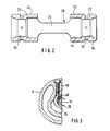
- Fig. 2 vergrößert die Hülse mit den beiden Lagerbuchsen,
- Fig. 3 einen Schnitt entlang Schnittlinie A, gemäß Fig. 1.
- 1 shows an axial longitudinal section through an exhaust gas turbocharger,
- 2 enlarges the sleeve with the two bearing bushes,
- 3 shows a section along section line A according to FIG. 1.
In Fig. 1 ist links das Verdichtergehäuse 2 und rechts das Turbinengehäuse 4 dargestellt, die in bekannter Weise über ein Lagergehäuse 6 miteinander verbunden sind. Das Verdichterrad 10 ist ebenso wie das Turbinenrad 12 auf einer Welle 14 drehfest angeordnet. Zur axialen Lagerung im Lagergehäuse 6 dient ein Axiallager 16. Durch eine Bohrung 18 wird Drucköl, insbesondere vom Motor, dem Lagergehäuse 6 zugeführt, um in gewohnter Weise zur Schmierung und Kühlung der Lager zu dienen.1 shows the compressor housing 2 on the left and the turbine housing 4 on the right, which are connected to one another in a known manner via a bearing
Die Welle 14 weist einen relativ kleinen Durchmesser auf und ist in einer Innenbohrung des Lagergehäuses 6 mittels zwei axial beabstandeten Lagerbuchsen 20, 22 radial gelagert. Die beiden Lagerbuchsen 20, 22 sind mittels zweier axial verlaufenden schmalen Stegen 24 miteinander zu einer Hülse 26 integriert. In der Zeichnung ist hier nur der eine Steg 24, der hinter der Zeichenebene liegt, zu erkennen. Ein weiterer Steg ist entsprechend vor der Zeichnebene vorgesehen. Die Hülse 26 weist somit zwischen den beiden Stegen 24 jeweils eine als Langloch ausgebildete Durchbrechung 28 auf. Die beiden Stege 24 sind im wesentlichen in einer Radialebene jeweils seitlich der Welle 14 angeordnet, und durch die vertikal unterhalb befindliche Durchbrechung 28 kann das Schmiermittel ungehindert abfließen; ein Stauen von Öl im mittleren Bereich der Hülse und daraus resultierende Verluste werden vermieden. Erfindungsgemäß weisen ferner die beiden Stege 24 in axialer Richtung näherungsweise die gleiche Länge auf wie die nachfolgend noch zu erläuternden äußeren Mantelflächen 32 der beiden Lagerbuchsen 20, 22. Die Hülse 26 wird mittels Sicherungsringen 30 axial gesichert. Wesentlich ist, daß die axiale Lagerung ausschließlich mittels des Axiallagers 16 erfolgt, wobei die Hülse 26 zwischen den Sicherungsringen 30 mit Spiel in dem Lagergehäuse 6 angeordnet ist. Durch die erfindungsgemäß als in axialer Richtung sich erstreckende Langlöcher ausgebildeten Durchbrechungen 28 wird die Gesamtmasse der Hülse minimiert und die freie Bewegbarkeit der Hülse bei wesentlich reduzierten Massekräften realisiert.The
Wie aus der vergrößerten Darstellung gemäß Fig. 2 ersichtlich, weist die äußere Mantelfläche 32 axial eine größere Länge auf als die innere Lagerfläche 34. Zwischen der Innenfläche 36 der Bohrung des Lagergehäuses 6 und der Mantelfläche 32 ist somit ein Quetschölspalt vorhanden, der eine wesentlich größere Fläche und axiale Länge aufweist, als die innere Lagerfläche. Es bildet sich erfindungsgemäß ein großer Quetschölfilm aus, und eine funktionssichere Dämpfung aufgrund dieses Quetschölspaltes wird erreicht. Im Rahmen dieser Erfindung führt zu dem Quetschölspalt jeder Lagerstelle jeweils eine Bohrung 38, 40, durch welche das Drucköl zugeführt wird. Die an den beiden axialen Stirnflächen der Lagerbuchsen 20, 22 bzw. der Hülse 26 zur Fixierung der Hülse angeordneten Sicherungsringe 30 dienen gleichzeitig auch als Drosselelemente des Quetschölspaltes, wodurch ein zuverlässiger Druckaufbau gewährleistet wird. Auch die inneren Enden der Mantelflächen sind als Drosselstellen ausgebildet. Dies erfolgt erfindungsgemäß einfach dadurch, daß die beim Einbringen der Durchbrechungen bei der Herstellung der Stege 24 erzeugten Grate stehengelassen werden, welche geringfügig über die Mantelfläche radial nach außen vorstehen. Die beiden Lagerbuchsen weisen jeweils zwei äußere Umfangsnuten mit vier über den Umfang gleichmäßig verteilten Radialbohrungen 42 auf, durch welche das Drucköl zu den inneren Lagerflächen 34 gelangt. Erfindungsgemäß schließen sich zur Mitte hin axial an die innere Lagerfläche 34 Erweiterungen 44 mit vergrößertem Durchmesser an. Diese Erweiterungen 44 gehen dann kontinuierlich in die Stege 24 über, die ebenfalls einen entsprechenden radialen Abstand zur Welle 14 aufweisen; die beiden Erweiterungen 44 weisen eine axiale Erstreckung in der Größenordnung der Lagerflächen auf. Die innere Lagerfläche 34 ist somit wesentlich kleiner als die äußere Mantelfläche 32, und die Reibungsverluste können folglich klein gehalten werden.As can be seen from the enlarged representation according to FIG. 2, the outer
Fig. 3 zeigt die Mittel zur Festlegung bzw. zur Verhinderung der Rotation der Hülse 26. Von der Hülse 26 ist hier der eine Steg 24 zu erkennen. Im Lagergehäuse 6 befindet sich ein Sicherungsstift 46, dessen Spitze auf der Seitenfläche 48 des Steges 24 aufliegt. Es ist eine im wesentlichen punktartige Auflagerung geschaffen, so daß im übrigen die Bewegbarkeit der Hülse 26 nicht beeinträchtigt wird. Mittels des Sicherungsstiftes 46 wird ausschließlich die Rotation unterbunden. Im Rahmen der Erfindung greift der Stift 46 im wesentlichen in der Mitte zwischen den beiden Lagerbuchsen 20, 22 an. Im übrigen ist die Hülse 26 entsprechend dem Spiel zwischen Mantelfläche und Lagergehäuse einerseits sowie zwischen der inneneren Lagerfläche 34 und Welle 14 andererseits und ferner dem Spiel zu den Sicherungsringen frei schwimmend angeordnet. Mittels des Sicherungsstiftes 46 erfolgt keinerlei Festlegung in axialer Richtung. Wesentlich ist ferner, daß der Sicherungsstift 46 nicht in radialer Richtung, sondern parallel zu einer Radialebene angeordnet ist. Das Anschlagen der Welle an den aufgrund von Fertigungstoleranzen zu weit eingeschraubten Sicherungsstift 46 wird vermieden. Die in axialer Richtung sich erstreckenden Stege 24 sind relativ schmal ausgebildet und gewährleisten gleichwohl eine starre Verbindung zwischen den beiden axial beabstandet angeordneten Lagerbuchsen. Die erfindungsgemäßen zwei Stege 24 werden mit geringem Fertigungsaufwand durch Entfernen des ursprünglich im Bereich der Durchbrechungen 28 vorhandenen Materials hergestellt.Fig. 3 shows the means for fixing or preventing the rotation of the
- 2 Verdichtergehäuse2 compressor housings
- 4 Turbinengehäuse4 turbine housings
- 6 Lagergehäuse6 bearing housings
- 10 Verdichterrad10 compressor wheel
- 12 Turbinenrad12 turbine wheel
- 14 Welle14 wave
- 16 Axiallager16 thrust bearings
- 18 Bohrung18 hole
- 20, 22 Lagerbuchse20, 22 bearing bush
- 24 Steg24 bridge
- 26 Hülse26 sleeve
- 28 Durchbrechung28 breakthrough
- 30 Sicherungsring30 circlip
- 32 Mantelfläche32 lateral surface
- 34 innere Lagerfläche34 inner storage area
- 36 Innenbohrung36 inner bore
- 38, 40 Bohrung38, 40 hole
- 42 Zulaufbohrung42 inlet bore
- 44 Erweiterung44 extension
- 46 Sicherungsstift46 locking pin
- 48 Seitenfläche48 side surface
Claims (10)
dadurch gekennzeichnet, daß die Hülse (26) in zwei axial beabstandete Lagerbuchsen (20, 22) mit den Lagerflächen (34) unterteilt ist,
daß die beiden Lagerbuchsen (20, 22) mittels schmalen steifen Stegen (24) miteinander verbunden sind
und daß die Sicherungsmittel einen Stift (26) enthalten, der an einem der Stege (24) angreift.1. Exhaust gas turbocharger with a sleeve (26) arranged in a bearing housing (6) for the radial mounting of a shaft (14), the sleeve (26) having an inner bearing surface (34) and an outer lateral surface at each of its two axial end regions Securing means arranged in the bearing housing (6), by means of which the sleeve (26) in the bore (36) of the bearing housing (6) is secured against rotation, the lubricant present in a gap between the sleeve (26) and the bore (36) damping causes
characterized in that the sleeve (26) is divided into two axially spaced bearing bushes (20, 22) with the bearing surfaces (34),
that the two bearing bushes (20, 22) are connected to one another by means of narrow, rigid webs (24)
and that the securing means include a pin (26) which engages one of the webs (24).
Priority Applications (1)
| Application Number | Priority Date | Filing Date | Title |
|---|---|---|---|
| AT87100217T ATE41973T1 (en) | 1986-01-16 | 1987-01-09 | EXHAUST TURBOCHARGER. |
Applications Claiming Priority (2)
| Application Number | Priority Date | Filing Date | Title |
|---|---|---|---|
| DE19863601082 DE3601082A1 (en) | 1986-01-16 | 1986-01-16 | EXHAUST TURBOCHARGER |
| DE3601082 | 1986-01-16 |
Publications (2)
| Publication Number | Publication Date |
|---|---|
| EP0230885A1 true EP0230885A1 (en) | 1987-08-05 |
| EP0230885B1 EP0230885B1 (en) | 1989-04-05 |
Family
ID=6291942
Family Applications (1)
| Application Number | Title | Priority Date | Filing Date |
|---|---|---|---|
| EP87100217A Expired EP0230885B1 (en) | 1986-01-16 | 1987-01-09 | Turbocharger |
Country Status (6)
| Country | Link |
|---|---|
| US (1) | US4738548A (en) |
| EP (1) | EP0230885B1 (en) |
| JP (1) | JPS62170727A (en) |
| AT (1) | ATE41973T1 (en) |
| BR (1) | BR8700144A (en) |
| DE (2) | DE3601082A1 (en) |
Cited By (4)
| Publication number | Priority date | Publication date | Assignee | Title |
|---|---|---|---|---|
| EP0339601A1 (en) * | 1988-04-26 | 1989-11-02 | Nissan Motor Co., Ltd. | Bearing holding arrangement in supercharger |
| WO1991009211A2 (en) * | 1989-12-12 | 1991-06-27 | Allied-Signal Inc. | Turbocharger bearing retention and lubrication system |
| EP1998010A3 (en) * | 2007-05-30 | 2010-07-21 | Bosch Mahle Turbo Systems GmbH & Co. KG | Bearing arrangement of a turbocharger |
| EP1762713A3 (en) * | 2005-09-09 | 2012-03-28 | IHI Corporation | Bearing structure of motor-driven supercharger |
Families Citing this family (29)
| Publication number | Priority date | Publication date | Assignee | Title |
|---|---|---|---|---|
| DE3712444A1 (en) * | 1987-04-11 | 1988-10-27 | Kuehnle Kopp Kausch Ag | EXHAUST TURBOCHARGER STORAGE |
| JPH0830501B2 (en) * | 1988-06-07 | 1996-03-27 | 日産自動車株式会社 | Bearing fixing device |
| US4902144A (en) * | 1989-05-02 | 1990-02-20 | Allied-Signal, Inc. | Turbocharger bearing assembly |
| DE3936069A1 (en) * | 1989-10-28 | 1991-05-02 | Kuehnle Kopp Kausch Ag | Turbocharger bearing device - has non-circular cylindrical bearing bush surfaces |
| US5232342A (en) * | 1990-07-07 | 1993-08-03 | David Brown Engineering Limited | High pressure multi-stage centrifugal pumps |
| DE4230037A1 (en) * | 1991-09-09 | 1993-03-11 | Aisin Seiki | CENTRIFUGAL RECHARGE BLOWER |
| JP2759754B2 (en) * | 1994-06-07 | 1998-05-28 | 川崎重工業株式会社 | Ceramic gas turbine rotor |
| US5974802A (en) * | 1997-01-27 | 1999-11-02 | Alliedsignal Inc. | Exhaust gas recirculation system employing a fluidic pump |
| GB0025248D0 (en) * | 2000-10-13 | 2000-11-29 | Holset Engineering Co | A turbine |
| DE10238415B4 (en) * | 2002-08-22 | 2016-08-11 | Volkswagen Ag | Slide bearing for a shaft of an exhaust gas turbocharger |
| DE10311996B4 (en) * | 2003-03-19 | 2005-02-24 | Mtu Friedrichshafen Gmbh | Arrangement of an exhaust gas turbocharger with a carrier housing |
| DE102007036916A1 (en) | 2007-08-06 | 2009-02-19 | Voith Patent Gmbh | Turbocharger, particularly exhaust gas turbocharger for combustion engine, has turbine, which has turbine rotor, compressor, which has compressor rotor and shaft on which turbine rotor and compressor rotor are mounted in torque proof manner |
| DE102007036913A1 (en) | 2007-08-06 | 2010-12-02 | Voith Patent Gmbh | Turbocharger, particularly supercharger for internal-combustion engine, has turbine, compressor and shaft, on which turbine rotor and compressor rotor are installed in pivoted manner |
| US8961128B2 (en) | 2009-08-26 | 2015-02-24 | Honeywell International Inc. | Bearing spacer and housing |
| US8496452B2 (en) | 2009-08-26 | 2013-07-30 | Honeywell International Inc. | Bearing spacer and housing |
| DE112011102728T5 (en) * | 2010-08-16 | 2013-06-13 | Borgwarner Inc. | Bearing housing of an exhaust gas turbocharger |
| US8967977B2 (en) | 2010-08-30 | 2015-03-03 | United Technologies Corporation | Locked spacer for a gas turbine engine shaft |
| JP2013079591A (en) * | 2011-10-03 | 2013-05-02 | Ihi Corp | Supercharger |
| CN102337962B (en) * | 2011-11-01 | 2013-07-17 | 湖南天雁机械有限责任公司 | Rotation stopping device of turbosupercharger for marine |
| US9121304B2 (en) | 2012-09-11 | 2015-09-01 | Honeywell International Inc. | Outer race locating washer |
| JP5811071B2 (en) * | 2012-11-02 | 2015-11-11 | トヨタ自動車株式会社 | Turbocharger bearing structure |
| DE102013113710B4 (en) | 2013-12-09 | 2023-05-11 | Ihi Charging Systems International Gmbh | Bearing device for an exhaust gas turbocharger and exhaust gas turbocharger |
| DE102014213330A1 (en) * | 2014-07-09 | 2016-01-14 | Bosch Mahle Turbo Systems Gmbh & Co. Kg | loader |
| US9638138B2 (en) * | 2015-03-09 | 2017-05-02 | Caterpillar Inc. | Turbocharger and method |
| US9739238B2 (en) * | 2015-03-09 | 2017-08-22 | Caterpillar Inc. | Turbocharger and method |
| US9683520B2 (en) * | 2015-03-09 | 2017-06-20 | Caterpillar Inc. | Turbocharger and method |
| US9752536B2 (en) * | 2015-03-09 | 2017-09-05 | Caterpillar Inc. | Turbocharger and method |
| US20160281647A1 (en) * | 2015-03-09 | 2016-09-29 | Caterpillar Inc. | Turbocharger and Method |
| USD837667S1 (en) * | 2017-10-20 | 2019-01-08 | Great American Merchandise & Events, Llc | Floating thermometer |
Citations (6)
| Publication number | Priority date | Publication date | Assignee | Title |
|---|---|---|---|---|
| CH211645A (en) * | 1938-05-04 | 1940-10-15 | Miag Muehlenbau & Ind Ag | Plant for heating and cooling grain. |
| GB908567A (en) * | 1960-06-09 | 1962-10-17 | Eng Productions Clevedon Ltd | Improved turbocharger bearing assembly |
| DE1400440A1 (en) * | 1961-09-28 | 1969-04-03 | Thompson Ramo Wooldridge Inc | Bearings for high-speed shafts |
| DE7337624U (en) * | 1974-01-24 | Kuehnle Ag Kopp & Kausch | Storage of the shaft of an exhaust gas turbocharger | |
| US3811741A (en) * | 1972-12-26 | 1974-05-21 | Garrett Corp | Bearing |
| DE2403768A1 (en) * | 1974-01-26 | 1975-08-07 | Josef Dr Ing Reisacher | STORAGE OF HIGH-SPEED ROTORS, IN PARTICULAR OF EXHAUST GAS TURBOCHARGERS |
Family Cites Families (6)
| Publication number | Priority date | Publication date | Assignee | Title |
|---|---|---|---|---|
| CA718715A (en) * | 1965-09-28 | Schwitzer Corporation | Bearing structure | |
| US3395949A (en) * | 1964-07-16 | 1968-08-06 | Union Carbide Corp | Gas-bearing assembly |
| US3448632A (en) * | 1967-11-15 | 1969-06-10 | Scully Intern Corp | Self-adjusting hydrostatic lead screw and nut assembly |
| US4256441A (en) * | 1979-06-19 | 1981-03-17 | Wallace-Murray Corporation | Floating ring bearing structure and turbocharger employing same |
| JPS58119926A (en) * | 1982-01-06 | 1983-07-16 | Hitachi Ltd | Bearing device for supercharger |
| US4613288A (en) * | 1983-05-26 | 1986-09-23 | The Garrett Corporation | Turbocharger |
-
1986
- 1986-01-16 DE DE19863601082 patent/DE3601082A1/en active Granted
-
1987
- 1987-01-09 EP EP87100217A patent/EP0230885B1/en not_active Expired
- 1987-01-09 AT AT87100217T patent/ATE41973T1/en not_active IP Right Cessation
- 1987-01-09 DE DE8787100217T patent/DE3760089D1/en not_active Expired
- 1987-01-09 US US07/001,909 patent/US4738548A/en not_active Expired - Lifetime
- 1987-01-15 BR BR8700144A patent/BR8700144A/en not_active IP Right Cessation
- 1987-01-16 JP JP62007977A patent/JPS62170727A/en active Pending
Patent Citations (6)
| Publication number | Priority date | Publication date | Assignee | Title |
|---|---|---|---|---|
| DE7337624U (en) * | 1974-01-24 | Kuehnle Ag Kopp & Kausch | Storage of the shaft of an exhaust gas turbocharger | |
| CH211645A (en) * | 1938-05-04 | 1940-10-15 | Miag Muehlenbau & Ind Ag | Plant for heating and cooling grain. |
| GB908567A (en) * | 1960-06-09 | 1962-10-17 | Eng Productions Clevedon Ltd | Improved turbocharger bearing assembly |
| DE1400440A1 (en) * | 1961-09-28 | 1969-04-03 | Thompson Ramo Wooldridge Inc | Bearings for high-speed shafts |
| US3811741A (en) * | 1972-12-26 | 1974-05-21 | Garrett Corp | Bearing |
| DE2403768A1 (en) * | 1974-01-26 | 1975-08-07 | Josef Dr Ing Reisacher | STORAGE OF HIGH-SPEED ROTORS, IN PARTICULAR OF EXHAUST GAS TURBOCHARGERS |
Cited By (7)
| Publication number | Priority date | Publication date | Assignee | Title |
|---|---|---|---|---|
| EP0339601A1 (en) * | 1988-04-26 | 1989-11-02 | Nissan Motor Co., Ltd. | Bearing holding arrangement in supercharger |
| US4943170A (en) * | 1988-04-26 | 1990-07-24 | Nissan Motor Company, Limited | Bearing holding arrangement in supercharger |
| WO1991009211A2 (en) * | 1989-12-12 | 1991-06-27 | Allied-Signal Inc. | Turbocharger bearing retention and lubrication system |
| WO1991009211A3 (en) * | 1989-12-12 | 1991-07-25 | Allied Signal Inc | Turbocharger bearing retention and lubrication system |
| US5076766A (en) * | 1989-12-12 | 1991-12-31 | Allied-Signal Inc. | Turbocharger bearing retention and lubrication system |
| EP1762713A3 (en) * | 2005-09-09 | 2012-03-28 | IHI Corporation | Bearing structure of motor-driven supercharger |
| EP1998010A3 (en) * | 2007-05-30 | 2010-07-21 | Bosch Mahle Turbo Systems GmbH & Co. KG | Bearing arrangement of a turbocharger |
Also Published As
| Publication number | Publication date |
|---|---|
| US4738548A (en) | 1988-04-19 |
| DE3601082A1 (en) | 1987-07-23 |
| EP0230885B1 (en) | 1989-04-05 |
| JPS62170727A (en) | 1987-07-27 |
| ATE41973T1 (en) | 1989-04-15 |
| BR8700144A (en) | 1987-12-01 |
| DE3760089D1 (en) | 1989-05-11 |
| DE3601082C2 (en) | 1988-01-28 |
Similar Documents
| Publication | Publication Date | Title |
|---|---|---|
| EP0230885B1 (en) | Turbocharger | |
| EP0286883B1 (en) | Turbo charger bearing arrangement | |
| DE102005007297B4 (en) | Fluid dynamic air bearing system for pivotal mounting of an engine | |
| DE69513473T2 (en) | Hydrodynamic bearing and seal | |
| EP0440917B1 (en) | Bearing arrangement for a turbocharger | |
| DE102004045629B4 (en) | Fluid dynamic storage system | |
| EP2167839B1 (en) | Balancing shaft | |
| DE102005036214B4 (en) | Fluid dynamic storage system | |
| DE3628687C2 (en) | ||
| DE3124462A1 (en) | "ARRANGEMENT FOR THE STORAGE OF A ROTOR, WHICH ENABLES A SAFE RUNNING OF THE ROTOR EVEN IF A DYNAMIC BALANCE COMES IN" | |
| EP2426374A1 (en) | Balancing shaft | |
| EP0976938A2 (en) | Radial bearing with viscous damping mechanism | |
| WO2016116105A1 (en) | Bearing assembly and exhaust gas turbocharger | |
| DE102010052892A1 (en) | Bearing arrangement for a shaft of a turbine wheel | |
| EP3377785B1 (en) | Torsional vibration damper having a bearing device and method for producing the bearing device | |
| DE19828817A1 (en) | Turbine rotor with releasably connected blade disks | |
| DE2251614A1 (en) | FLEXIBLE SHAFT FOR TRANSMISSION OF ROTATING FORCE | |
| DE3936069A1 (en) | Turbocharger bearing device - has non-circular cylindrical bearing bush surfaces | |
| EP0949419B1 (en) | Internal gear pump | |
| DE19961788B4 (en) | Two-stage planetary gear set with little play | |
| CH621827A5 (en) | ||
| DE102005005414B3 (en) | Fluid-dynamic bearing system for rotary bearing of spindle motor used in hard disk drive assembly, has bushings surrounding divided sections of tubular case surrounding rotary shaft, forming gap which is filled with bearing fluid | |
| DE102005012083A1 (en) | Bearing for shaft has double-walled tube filled with oil mounted between it and shaft to reduce vibration and noise | |
| DE202005000155U1 (en) | Fluid dynamic storage system | |
| DE102017120760A1 (en) | Axialluftlageranordnung |
Legal Events
| Date | Code | Title | Description |
|---|---|---|---|
| PUAI | Public reference made under article 153(3) epc to a published international application that has entered the european phase |
Free format text: ORIGINAL CODE: 0009012 |
|
| 17P | Request for examination filed |
Effective date: 19870109 |
|
| AK | Designated contracting states |
Kind code of ref document: A1 Designated state(s): AT DE FR GB IT |
|
| 17Q | First examination report despatched |
Effective date: 19880321 |
|
| GRAA | (expected) grant |
Free format text: ORIGINAL CODE: 0009210 |
|
| AK | Designated contracting states |
Kind code of ref document: B1 Designated state(s): AT DE FR GB IT |
|
| REF | Corresponds to: |
Ref document number: 41973 Country of ref document: AT Date of ref document: 19890415 Kind code of ref document: T |
|
| ITF | It: translation for a ep patent filed | ||
| REF | Corresponds to: |
Ref document number: 3760089 Country of ref document: DE Date of ref document: 19890511 |
|
| ET | Fr: translation filed | ||
| GBT | Gb: translation of ep patent filed (gb section 77(6)(a)/1977) | ||
| PLBE | No opposition filed within time limit |
Free format text: ORIGINAL CODE: 0009261 |
|
| STAA | Information on the status of an ep patent application or granted ep patent |
Free format text: STATUS: NO OPPOSITION FILED WITHIN TIME LIMIT |
|
| 26N | No opposition filed | ||
| ITTA | It: last paid annual fee | ||
| PGFP | Annual fee paid to national office [announced via postgrant information from national office to epo] |
Ref country code: GB Payment date: 19931220 Year of fee payment: 8 |
|
| PGFP | Annual fee paid to national office [announced via postgrant information from national office to epo] |
Ref country code: FR Payment date: 19940104 Year of fee payment: 8 |
|
| PGFP | Annual fee paid to national office [announced via postgrant information from national office to epo] |
Ref country code: AT Payment date: 19940114 Year of fee payment: 8 |
|
| PGFP | Annual fee paid to national office [announced via postgrant information from national office to epo] |
Ref country code: DE Payment date: 19940207 Year of fee payment: 8 |
|
| PG25 | Lapsed in a contracting state [announced via postgrant information from national office to epo] |
Ref country code: GB Effective date: 19950109 Ref country code: AT Effective date: 19950109 |
|
| GBPC | Gb: european patent ceased through non-payment of renewal fee |
Effective date: 19950109 |
|
| PG25 | Lapsed in a contracting state [announced via postgrant information from national office to epo] |
Ref country code: FR Effective date: 19950929 |
|
| PG25 | Lapsed in a contracting state [announced via postgrant information from national office to epo] |
Ref country code: DE Effective date: 19951003 |
|
| REG | Reference to a national code |
Ref country code: FR Ref legal event code: ST |
|
| PG25 | Lapsed in a contracting state [announced via postgrant information from national office to epo] |
Ref country code: IT Free format text: LAPSE BECAUSE OF NON-PAYMENT OF DUE FEES;WARNING: LAPSES OF ITALIAN PATENTS WITH EFFECTIVE DATE BEFORE 2007 MAY HAVE OCCURRED AT ANY TIME BEFORE 2007. THE CORRECT EFFECTIVE DATE MAY BE DIFFERENT FROM THE ONE RECORDED. Effective date: 20050109 |