EP0269480A1 - Revêtement métallique réalisé sur un substrat minéral - Google Patents
Revêtement métallique réalisé sur un substrat minéral Download PDFInfo
- Publication number
- EP0269480A1 EP0269480A1 EP87402364A EP87402364A EP0269480A1 EP 0269480 A1 EP0269480 A1 EP 0269480A1 EP 87402364 A EP87402364 A EP 87402364A EP 87402364 A EP87402364 A EP 87402364A EP 0269480 A1 EP0269480 A1 EP 0269480A1
- Authority
- EP
- European Patent Office
- Prior art keywords
- metallic
- metallic coating
- intermediate layer
- substrate
- mineral substrate
- Prior art date
- Legal status (The legal status is an assumption and is not a legal conclusion. Google has not performed a legal analysis and makes no representation as to the accuracy of the status listed.)
- Granted
Links
Images


Classifications
-
- C—CHEMISTRY; METALLURGY
- C23—COATING METALLIC MATERIAL; COATING MATERIAL WITH METALLIC MATERIAL; CHEMICAL SURFACE TREATMENT; DIFFUSION TREATMENT OF METALLIC MATERIAL; COATING BY VACUUM EVAPORATION, BY SPUTTERING, BY ION IMPLANTATION OR BY CHEMICAL VAPOUR DEPOSITION, IN GENERAL; INHIBITING CORROSION OF METALLIC MATERIAL OR INCRUSTATION IN GENERAL
- C23C—COATING METALLIC MATERIAL; COATING MATERIAL WITH METALLIC MATERIAL; SURFACE TREATMENT OF METALLIC MATERIAL BY DIFFUSION INTO THE SURFACE, BY CHEMICAL CONVERSION OR SUBSTITUTION; COATING BY VACUUM EVAPORATION, BY SPUTTERING, BY ION IMPLANTATION OR BY CHEMICAL VAPOUR DEPOSITION, IN GENERAL
- C23C28/00—Coating for obtaining at least two superposed coatings either by methods not provided for in a single one of groups C23C2/00 - C23C26/00 or by combinations of methods provided for in subclasses C23C and C25C or C25D
-
- C—CHEMISTRY; METALLURGY
- C04—CEMENTS; CONCRETE; ARTIFICIAL STONE; CERAMICS; REFRACTORIES
- C04B—LIME, MAGNESIA; SLAG; CEMENTS; COMPOSITIONS THEREOF, e.g. MORTARS, CONCRETE OR LIKE BUILDING MATERIALS; ARTIFICIAL STONE; CERAMICS; REFRACTORIES; TREATMENT OF NATURAL STONE
- C04B41/00—After-treatment of mortars, concrete, artificial stone or ceramics; Treatment of natural stone
- C04B41/45—Coating or impregnating, e.g. injection in masonry, partial coating of green or fired ceramics, organic coating compositions for adhering together two concrete elements
- C04B41/52—Multiple coating or impregnating multiple coating or impregnating with the same composition or with compositions only differing in the concentration of the constituents, is classified as single coating or impregnation
-
- C—CHEMISTRY; METALLURGY
- C23—COATING METALLIC MATERIAL; COATING MATERIAL WITH METALLIC MATERIAL; CHEMICAL SURFACE TREATMENT; DIFFUSION TREATMENT OF METALLIC MATERIAL; COATING BY VACUUM EVAPORATION, BY SPUTTERING, BY ION IMPLANTATION OR BY CHEMICAL VAPOUR DEPOSITION, IN GENERAL; INHIBITING CORROSION OF METALLIC MATERIAL OR INCRUSTATION IN GENERAL
- C23C—COATING METALLIC MATERIAL; COATING MATERIAL WITH METALLIC MATERIAL; SURFACE TREATMENT OF METALLIC MATERIAL BY DIFFUSION INTO THE SURFACE, BY CHEMICAL CONVERSION OR SUBSTITUTION; COATING BY VACUUM EVAPORATION, BY SPUTTERING, BY ION IMPLANTATION OR BY CHEMICAL VAPOUR DEPOSITION, IN GENERAL
- C23C4/00—Coating by spraying the coating material in the molten state, e.g. by flame, plasma or electric discharge
- C23C4/02—Pretreatment of the material to be coated, e.g. for coating on selected surface areas
-
- Y—GENERAL TAGGING OF NEW TECHNOLOGICAL DEVELOPMENTS; GENERAL TAGGING OF CROSS-SECTIONAL TECHNOLOGIES SPANNING OVER SEVERAL SECTIONS OF THE IPC; TECHNICAL SUBJECTS COVERED BY FORMER USPC CROSS-REFERENCE ART COLLECTIONS [XRACs] AND DIGESTS
- Y10—TECHNICAL SUBJECTS COVERED BY FORMER USPC
- Y10T—TECHNICAL SUBJECTS COVERED BY FORMER US CLASSIFICATION
- Y10T428/00—Stock material or miscellaneous articles
- Y10T428/12—All metal or with adjacent metals
- Y10T428/12493—Composite; i.e., plural, adjacent, spatially distinct metal components [e.g., layers, joint, etc.]
- Y10T428/12535—Composite; i.e., plural, adjacent, spatially distinct metal components [e.g., layers, joint, etc.] with additional, spatially distinct nonmetal component
- Y10T428/12542—More than one such component
- Y10T428/12549—Adjacent to each other
-
- Y—GENERAL TAGGING OF NEW TECHNOLOGICAL DEVELOPMENTS; GENERAL TAGGING OF CROSS-SECTIONAL TECHNOLOGIES SPANNING OVER SEVERAL SECTIONS OF THE IPC; TECHNICAL SUBJECTS COVERED BY FORMER USPC CROSS-REFERENCE ART COLLECTIONS [XRACs] AND DIGESTS
- Y10—TECHNICAL SUBJECTS COVERED BY FORMER USPC
- Y10T—TECHNICAL SUBJECTS COVERED BY FORMER US CLASSIFICATION
- Y10T428/00—Stock material or miscellaneous articles
- Y10T428/12—All metal or with adjacent metals
- Y10T428/12493—Composite; i.e., plural, adjacent, spatially distinct metal components [e.g., layers, joint, etc.]
- Y10T428/12535—Composite; i.e., plural, adjacent, spatially distinct metal components [e.g., layers, joint, etc.] with additional, spatially distinct nonmetal component
- Y10T428/12611—Oxide-containing component
Definitions
- the invention relates to metallic coatings to be produced on natural or synthetic mineral substrates such as sandstone, various rocks, sintered aluminum oxides, sintered or molten ceramic materials and any other non-weldable material.
- metallic coatings can be made on a substrate by the techniques of hot spraying of a filler material constituted by a metallic alloy known as “autofusistill” in the form of molten particles or in a pasty state which, by the effect of the speed to which they are subjected, come crashing onto the substrate, forming a more or less porous and more or less adherent layer.
- the filler material may be in the form of solid wires, filled wires, rods, flexible cords, powders.
- the temperature to which the particles are brought can be obtained by gas combustions or electric arcs.
- the speed of particles, caused by the action of compressed gases from combustion flames or columns of plasmas, can vary from a few meters per second to several times the speed of sound.
- flame pistols including detonation guns and electric arc pistols including plasma generators are used for this hot spraying.
- the deposited layer can be densified in order to eliminate all the porosities and to obtain a sealed metallic deposit by effecting a fusion of this layer, by heating, for example, by induction, gas, laser and electron beam, metal or metal alloy.
- the present invention aims to make this possible and it provides for this purpose an intermediate layer which also allows to absorb the stresses due to the melting and removal of the metal alloy constituting the metal coating and which can , if the mineral substrate is made up of several parts, temporarily hold them in position during projection and reflow this metallic alloy and then contribute to their final maintenance.
- An object of the invention is thus a metallic coating produced on a mineral substrate by hot spraying of a metallic alloy, characterized in that it is carried out on an intermediate layer of a refractory metallic alloy chosen from the list of nickel alloys -chrome and nickel and titanium aluminides, obtained by hot spraying.
- this intermediate layer is itself deposited on a ceramic sublayer taken from the list of aluminum and zirconium oxides and titanium hydrides, formed by hot spraying on the mineral substrate.
- This sub-layer further improves the adhesion of the intermediate layer to certain substrates and it possibly contributes to the maintenance of the parts forming the substrate.
- measurement probes are mounted on the mineral substrate and covered by said intermediate layer which holds them in place. These probes are embedded either in a portion of the thickness of the intermediate layer or in said sub-layer if it exists.
- the thickness of the sub-layer will generally be less than 0.5 mm and that of the intermediate layer and of said metallic coating will generally be less than 1 mm.
- this metallic coating has an outer surface made rough and serving as a support for a thicker porous surround, made of a material chosen from the list of metallic and ceramic materials, deposited by hot spraying.
- the thickness of this surround will generally be several millimeters in order to be able to achieve thermal insulation and circulate a fluid therein.
- the substrate consists of an axial succession of cylindrical cores taken from a natural formation, for example thirty sandstone cores with a diameter of 60 mm and a length of 100 mm placed end to end and kept pressed. against each other to form a whole substrate 3 meters long.
- the installation of FIG. 3 comprises a lathe on which the substrate 6 is held in axial compression between a mandrel 7 and a tailstock 8 and driven in rotation, while on the bench 9 of the lathe moves longitudinally a carriage 10 carrying a spray gun 11 and a coil 12 for winding a gun power cord.
- An extractor hood 13 moves at the same time as the carriage 10.
- These probes 14 extend longitudinally on the cores from the holes 15 or the locations which receive their active end, to reach one or the other of the two longitudinal ends of the axial succession of carrots.
- These probes 14 make it possible to determine the temperature difference between the inside of the cores and the external surface of the latter.
- tubular metal end pieces 16 made of stainless steel and discs of sintered material 17 so that it is thus possible to form, after execution of a sealed metal coating on all the carrots , a conduit in which the discs 17 ensure good distribution of a fluid through the cores.
- This fluid can be constituted, for example, by air or oxygen injected at very high temperature and one can follow the front of the combustion thus generated. We can in this way reconstitute in the laboratory operating conditions similar to those existing at the depth from which the cores were taken.
- a ceramic underlay 18 is deposited laterally on the axial succession of the cores by means of the installation of FIG. 3 in which the spray gun 11 is an oxy-acetylene flame gun fed by a flexible cord of the blue corundum type.
- the gun 11 is automatically moved in longitudinal translation while all the cores are rotated. A uniform sub-layer is thus obtained, the thickness of which is, for example, 0.3 mm.
- an intermediate layer 19 for example 0.7 mm thick, is deposited with the same installation and a flexible cord of nickel aluminide.
- This coating 20 is remelted by inductive heating using the installation of FIG. 4 which includes a tower such as that of FIG. 3, but the carriage 10 of which carries a high frequency generator 21.
- a thick ceramic coating 22 In the embodiment according to FIG. 2 to deposit on the metallic coating 20 a thick ceramic coating 22. To ensure the adhesion of this new deposit, the exterior surface of the metallic coating 20 has been etched with an abrasive jet, for example corundum. make this surface rough, the roughness being between 6 and 15 ⁇ Ra.
- the adhesion was improved by depositing, by hot spraying, a bonding layer of nickel aluminide with 5% aluminum, with a thickness of 50 to 100 ⁇ m. On this bonding layer, the thick ceramic coating 22, for example 10 mm thick, was sprayed hot, which serves as a thermal barrier.
- This coat ment thick 22 can in particular be obtained from a bead of blue alumina corundum with 3% titanium oxide.
- annular space 23 has been provided, formed for example between the covering 22 covered with a sealing layer 24 1 mm thick in a synthetic resin and an outer envelope 25 comprising an outer layer of coated KEVLAR fibers 26 4 mm thick and an inner layer of synthetic rubber 27 1 mm thick.
- the outer casing 25 is held at its longitudinal ends by conventional support means not shown here.
- the annular space 23 has, for example, a thickness of 2.5 mm and it is used for the circulation of a cooling fluid.
Landscapes
- Chemical & Material Sciences (AREA)
- Engineering & Computer Science (AREA)
- Materials Engineering (AREA)
- Organic Chemistry (AREA)
- Chemical Kinetics & Catalysis (AREA)
- Mechanical Engineering (AREA)
- Metallurgy (AREA)
- Ceramic Engineering (AREA)
- Physics & Mathematics (AREA)
- Plasma & Fusion (AREA)
- Structural Engineering (AREA)
- Coating By Spraying Or Casting (AREA)
Abstract
Description
- L'invention concerne des revêtements métalliques devant être réalisés sur des substrats minéraux naturels ou synthétiques tels que des grès, des roches diverses, des oxydes d'aluminium frittés, des matériaux céramiques frittés ou fondus et tout autre matériau non soudable.
- On sait que l'on peut effectuer des revêtements métalliques sur un substrat par les techniques de projection à chaud d'un matériau d'apport constitué par un alliage métallique dit "autofusiblé" sous forme de particules fondues ou à l'état pâteux qui, par l'effet de la vitesse à laquelle elles sont soumises, viennent s'écraser sur le substrat en formant une couche plus ou moins poreuse et plus ou moins adhérente. Le matériau d'apport peut se présenter sous forme de fils pleins, de fils fourrés, de baguettes, de cordons souples, de poudres. La température à laquelle sont portées les particules peut être obtenue par des combustions de gaz ou des arcs électriques. La vitesse des particules, provoquée par l'action de gaz comprimés de flammes de combustion ou de colonnes de plasmas, peut varier de quelques mètres par seconde à plusieurs fois la vitesse du son. On utilise pour cette projection à chaud des pistolets à flamme y compris des canons à détonation et des pistolets à arc électrique y compris des générateurs de plasmas.
- On sait aussi que l'on peut densifier la couche déposee afin d'éliminer toutes les porosités et d'obtenir un dépôt métallique étanche en effectuant une fusion de cette couche, par chauffage, par exemple, à induction, à gaz, à laser et à faisceau d'électrons, d'un métal ou d'un alliage métallique.
- Mais avec un substrat minéral, on se heurte à des difficultés d'adhérence du revêtement métallique telles que la réalisation d'un revêtement métallique étanche sur un substrat minéral paraissait jusqu'ici impossible.
- La présente invention a pour objectif de rendre cette réalisation possible et elle prévoit à cet effet une couche intermédiaire qui permet, en outre, d'encaisser les contraintes dues à la fusion et au retrait de l'alliage métallique constituant le revêtement métallique et qui peut, si le substrat minéral est formé de plusieurs pièces, maintenir temporairement celles-ci en position pendant la projection et la refusion de cet alliage métallique et contribuer ensuite à leur maintien définitif.
- Un objet de l'invention est ainsi un revêtement métallique réalisé sur un substrat minéral par projection à chaud d'un alliage métallique, caractérisé en ce qu'il est effectué sur une couche intermédiaire en un alliage métallique réfractaire choisi dans la liste des alliages nickel-chrome et des aluminiures de nickel et de titane, obtenue par projection à chaud.
- Selon un autre objet de l'invention, cette couche intermédiaire est elle-même déposée sur une sous-couche en une céramique prise dans la liste des oxydes d'aluminium et de zirconium et des hydrures de titane, formée par projection à chaud sur le substrat minéral. Cette sous-couche améliore encore l'adhérence de la couche intermédiaire sur certains substrats et elle contribue éventuellement au maintien des pièces formant le substrat.
- Selon un objet supplémentaire de l'invention, des sondes de mesure sont montées sur le substrat minéral et recouvertes par ladite couche intermédiaire qui les maintient en place. Ces sondes se trouvent noyées soit dans une portion de l'épaisseur de la couche intermédiaire soit dans ladite sous-couche si celle-ci existe.
- L'épaisseur de la sous-couche sera généralement inférieure à 0,5 mm et celle de la couche intermédiaire ainsi que dudit revêtement métallique sera généralement inférieure à 1 mm.
- Selon un objet complémentaire de l'invention, ce revêtement métallique présente une surface extérieure rendue rugueuse et servant de support à un entourage poreux plus épais, en un matériau choisi dans la liste des matériaux métalliques et céramiques, déposé par projection à chaud. L'épaisseur de cet entourage sera généralement de plusieurs millimètres afin de pouvoir réaliser une isolation thermique et y faire circuler un fluide.
- D'autres particularités de l'invention ressortiront d'un exemple de réalisation qui va être décrit, à titre non limitatif, en se référant au dessin joint dans lequel :
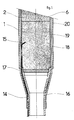
- - la Fig. 1 est une coupe axiale d'une portion d'un substrat sur lequel on a déposé une sous-couche, une couche intermédiaire et un revêtement métallique étanche ;
- - la Fig. 2 est une coupe axiale d'une portion d'un substrat ayant reçu les mêmes dépôts et en plus un dépôt extérieur épais en céramique ;
- - la Fig. 3 représente schématiquement, en élévation, une installation de projection de matériaux d'apport sur un substrat ; et
- - la Fig. 4 représente schématiquement, en élévation, une installation de refusion du revêtement métallique.
- Dans cet exemple, le substrat est constitué par une succession axiale de carottes cylindriques prélevées dans une formation naturelle, par exemple trente carottes en grès d'un diamètre de 60 mm et d'une longueur de 100 mm placées bout à bout et maintenues pressées les unes contre les autres pour former dans leur ensemble un substrat de 3 mètres de long. On voit deux de ces carottes en 1 et 2 sur la Fig. 1 et trois autres carottes 3, 4, 5 sur la Fig. 2. L'installation de la Fig. 3 comporte un tour sur lequel le substrat 6 est tenu en compression axiale entre un mandrin 7 et une contre-pointe 8 et entraîné en rotation, tandis que sur le banc 9 du tour se déplace longitudinalement un chariot 10 porteur d'un pistolet de projection 11 et d'une bobine 12 d'enroulement d'un cordon d'alimentation du pistolet. Une hotte d'aspiration 13 se déplace en même temps que le chariot 10.
- On voit sur les Fig. 1 et 2 des sondes de mesure 14, constituées ici par des thermocouples, dont l'extrémité active est introduite dans des trous 15 percés dans les carottes ou placée à la surface des carottes. Ces sondes 14 s'étendent longitudinalement sur les carottes à partir des trous 15 ou des emplacements qui reçoivent leur extrémité active, pour atteindre l'une ou l'autre des deux extrémités longitudinales de la succession axiale de carottes. Ces sondes 14 permettent de déterminer la différence de température entre l'intérieur des carottes et la surface extérieure de celles-ci.
- Aux extrémités axiales de l'ensemble des carottes sont disposés des embouts métalliques tubulaires 16 en acier inoxydable et des disques en matériau fritté 17 de sorte que l'on peut ainsi constituer, après exécution d'un revêtement métallique étanche sur l'ensemble des carottes, un conduit dans lequel les disques 17 assurent une bonne répartition d'un fluide à travers les carottes. Ce fluide peut être constitué, par exemple, par de l'air ou de l'oxygène injecté à très haute température et on peut suivre le front de la combustion ainsi engendrée. On peut de cette manière reconstituer en laboratoire des conditions opératoires similaires à celles existant à la profondeur à laquelle les carottes ont été prélevées.
- Une sous-couche en céramique 18 est déposée latéralement sur la succession axiale des carottes au moyen de l'installation de la Fig. 3 dans laquelle le pistolet de projection 11 est un pistolet à flamme oxy-acétylénique alimenté par un cordon souple du type corindon bleu. Le pistolet 11 est déplacé automatiquement en translation longitudinale tandis que l'ensemble des carottes est entraîné en rotation. On obtient ainsi une sous-couche uniforme dont l'épaisseur est, par exemple, de 0,3 mm.
- Sur cette sous-couche et sur une portion des embouts 16 on dépose avec la même installation et un cordon souple en aluminiure de nickel une couche intermédiaire 19, par exemple d'une épaisseur de 0,7 mm.
- De même, sur cette couche intermédiaire 19 et une portion supplémentaire des embouts 16, on effectue, à l'aide de l'installation de la Fig. 3 dans laquelle le pistolet 11 est utilisé avec un cordon souple autofusible à base de nickel, un revêtement métallique 20 d'une épaisseur de 0,8 mm, par exemple.
- Ce revêtement 20 est refondu par chauffage inductif à l'aide de l'installation de la Fig. 4 qui comporte un tour tel que celui de la Fig. 3, mais dont le chariot 10 porte un générateur à haute fréquence 21.
- On obtient ainsi autour de la succession axiale de carottes un revêtement étanche lié de manière étanche aux embouts 16, retenant les carottes les unes contre les autres et les sondes de mesure contre les carottes et appliqué latéralement contre la succession axiale de carottes.
- On a prévu dans la réalisation selon la Fig. 2 de déposer sur le revêtement métallique 20 un revêtement épais en céramique 22. Pour assurer l'adhérence de ce nouveau dépôt, on a décapé au jet d'abrasif, par exemple du corindon, la surface extérieure du revêtement métallique 20, de manière à rendre cette surface rugueuse, la rugosité étant comprise entre 6 et 15 µRa. On a amélioré l'adhérence en déposant, par projection à chaud, une couche d'accrochage en aluminiure de nickel à 5 % d'aluminium, d'une épaisseur de 50 à 100 µm. Sur cette couche d'accrochage on a projeté à chaud le revêtement épais en céramique 22, par exemple de 10 mm d'épaisseur, qui sert de barrière thermique. Ce revête ment épais 22 peut notamment être obtenu à partir d'un cordon de corindon bleu d'alumine à 3 % d'oxyde de titane.
- Dans la réalisation selon la Fig. 2, on a prévu un espace annulaire 23 formé par exemple entre le revêtement 22 recouvert d'une couche d'étanchéité 24 de 1 mm d'épaisseur en une résine synthétique et une enveloppe extérieure 25 comprenant une couche extérieure de fibres de KEVLAR enrobées 26 de 4 mm d'épaisseur et une couche intérieure en caoutchouc synthétique 27 de 1 mm d'épaisseur. L'enveloppe extérieure 25 est tenue à ses extrémités longitudinales par des moyens de support classiques non représentés ici. L'espace annulaire 23 a, par exemple, une épaisseur de 2,5 mm et il est utilisé pour la circulation d'un fluide de refroidissement.
Claims (5)
Applications Claiming Priority (2)
| Application Number | Priority Date | Filing Date | Title |
|---|---|---|---|
| FR8615319A FR2606037B1 (fr) | 1986-11-04 | 1986-11-04 | Revetement metallique realise sur un substrat mineral |
| FR8615319 | 1986-11-04 |
Publications (2)
| Publication Number | Publication Date |
|---|---|
| EP0269480A1 true EP0269480A1 (fr) | 1988-06-01 |
| EP0269480B1 EP0269480B1 (fr) | 1991-06-26 |
Family
ID=9340489
Family Applications (1)
| Application Number | Title | Priority Date | Filing Date |
|---|---|---|---|
| EP87402364A Expired - Lifetime EP0269480B1 (fr) | 1986-11-04 | 1987-10-21 | Revêtement métallique réalisé sur un substrat minéral |
Country Status (6)
| Country | Link |
|---|---|
| US (1) | US4839239A (fr) |
| EP (1) | EP0269480B1 (fr) |
| DE (1) | DE3771040D1 (fr) |
| ES (1) | ES2022914B3 (fr) |
| FR (1) | FR2606037B1 (fr) |
| GB (1) | GB2198151B (fr) |
Cited By (3)
| Publication number | Priority date | Publication date | Assignee | Title |
|---|---|---|---|---|
| EP0459865A1 (fr) * | 1990-05-31 | 1991-12-04 | Grumman Aerospace Corporation | Méthode pour protéger les surfaces céramiques |
| EP0480404A2 (fr) * | 1990-10-09 | 1992-04-15 | Daido Tokushuko Kabushiki Kaisha | Matériau métallique composite résistant à la corrosion et à la chaleur et son procédé de fabrication |
| WO1996027570A1 (fr) * | 1995-03-08 | 1996-09-12 | Societe Europeenne De Propulsion | Outillages utilisant des materiaux composites thermostructuraux contenant du carbone pour des installations de traitement thermique et/ou thermochimique |
Families Citing this family (13)
| Publication number | Priority date | Publication date | Assignee | Title |
|---|---|---|---|---|
| DE3907084A1 (de) * | 1989-03-04 | 1990-09-13 | Battelle Institut E V | Reversibler speicher fuer medien sowie anwendung des speichers |
| DE3910725C1 (fr) * | 1989-04-03 | 1990-10-31 | Hydraudyne Cylinders B., Boxtel, Nl | |
| EP0431093A1 (fr) * | 1989-05-10 | 1991-06-12 | Alcan International Limited | Fabrication de soupape en champignon |
| US5201939A (en) * | 1989-12-04 | 1993-04-13 | General Electric Company | Method of modifying titanium aluminide composition |
| US5714243A (en) * | 1990-12-10 | 1998-02-03 | Xerox Corporation | Dielectric image receiving member |
| US5232522A (en) * | 1991-10-17 | 1993-08-03 | The Dow Chemical Company | Rapid omnidirectional compaction process for producing metal nitride, carbide, or carbonitride coating on ceramic substrate |
| JP2763840B2 (ja) * | 1991-11-26 | 1998-06-11 | 大同ほくさん株式会社 | 断熱管体およびその製法 |
| FR2692314B1 (fr) * | 1992-06-10 | 1994-09-23 | Total Sa | Procédé de consolidation et d'étanchéification d'un échantillon de roche. |
| US5582874A (en) * | 1994-11-29 | 1996-12-10 | United Container Machinery Group, Inc. | Method for coating corrugating rolls using high velocity oxygen fueled thermal spray |
| US5711826A (en) * | 1996-04-12 | 1998-01-27 | Crs Holdings, Inc. | Functionally gradient cladding for nuclear fuel rods |
| US6175485B1 (en) | 1996-07-19 | 2001-01-16 | Applied Materials, Inc. | Electrostatic chuck and method for fabricating the same |
| US7278353B2 (en) * | 2003-05-27 | 2007-10-09 | Surface Treatment Technologies, Inc. | Reactive shaped charges and thermal spray methods of making same |
| US9499895B2 (en) * | 2003-06-16 | 2016-11-22 | Surface Treatment Technologies, Inc. | Reactive materials and thermal spray methods of making same |
Citations (7)
| Publication number | Priority date | Publication date | Assignee | Title |
|---|---|---|---|---|
| FR1090257A (fr) * | 1953-11-13 | 1955-03-29 | Libbey Owens Ford Glass Co | Articles en céramique ou verre recouverts d'un enduit conducteur |
| US3010480A (en) * | 1958-10-13 | 1961-11-28 | Clifford A Ragsdale | Thermocouple tube and protective coating |
| FR1434158A (fr) * | 1964-11-25 | 1966-04-08 | Sfec | Perfectionnements aux revêtements protecteurs réfractaires, et procédé de fabrication de ces éléments |
| FR1505106A (fr) * | 1965-12-15 | 1967-12-08 | Philips Nv | Composant électrique semi-conducteur et son procédé de fabrication |
| GB1133403A (en) * | 1967-03-31 | 1968-11-13 | Standard Telephones Cables Ltd | Deposition of metal layers on insulators |
| FR2037986A5 (en) * | 1969-03-14 | 1970-12-31 | Leybold Heraeus Verwaltung | Vacuum deposition of layers of transparent - material onto glass |
| DE2545242A1 (de) * | 1975-10-09 | 1977-04-21 | Metallgesellschaft Ag | Verfahren zum beschichten von kolben und/oder zylindern von brennkraftmaschinen |
Family Cites Families (21)
| Publication number | Priority date | Publication date | Assignee | Title |
|---|---|---|---|---|
| FR773928A (fr) * | 1934-12-29 | 1934-11-28 | Nat Standard Co | Perfectionnements aux objets en acier revêtus d'autres corps et procédés de fabrication desdits objets |
| GB949612A (en) * | 1959-06-26 | 1964-02-12 | Eaton Mfg Co | A process for supplying a coating on at least a portion of a metallic surface and a metal article produced in such process |
| DE1144418B (de) * | 1961-07-20 | 1963-02-28 | Siemens Planiawerke A G Fuer K | Verfahren zur Herstellung einer Kontaktschicht auf einem silizium-haltigen Werkstoff |
| DE1758169A1 (de) * | 1967-04-17 | 1971-01-14 | Mitsubishi Steel Mfg | Elektrode mit gegen Oxydation widerstandsfaehiger Schutzschicht und Verfahren zum UEberziehen der Elektrode mit einer solchen Schutzschicht |
| US3620808A (en) * | 1968-01-05 | 1971-11-16 | James E Monroe Jr | Method of forming a thermal emissivity coating on a metallic substrate |
| AT278983B (de) * | 1968-08-12 | 1970-02-25 | Plansee Metallwerk | Verfahren zur Herstellung von Drehanoden für Röntgenröhren |
| FR1600296A (fr) * | 1968-12-31 | 1970-07-20 | ||
| SE360347B (fr) * | 1969-05-02 | 1973-09-24 | Beers Ltd De | |
| US3967017A (en) * | 1970-03-17 | 1976-06-29 | John Anthony Marten | Method of coating a vehicle test bed rollers |
| GB1393031A (en) * | 1972-06-06 | 1975-05-07 | Sperl R J | Metal plating product and process |
| FR2201542B1 (fr) * | 1972-10-02 | 1977-09-09 | Bendix Corp | |
| US3814447A (en) * | 1972-11-02 | 1974-06-04 | Ramsey Corp | Sealing element for use in internal combustion engines |
| US3890069A (en) * | 1973-07-05 | 1975-06-17 | Ford Motor Co | Coating for rotary engine rotor housings and method of making |
| US3888746A (en) * | 1974-01-04 | 1975-06-10 | Ford Motor Co | Method of providing an intermediate steel layer for chrome plating on rotor housings |
| FR2334431A1 (fr) * | 1975-12-12 | 1977-07-08 | Gen Electric | Procede de depot par pulverisation thermique |
| DE2720726C3 (de) * | 1977-05-07 | 1980-12-18 | Brown, Boveri & Cie Ag, 6800 Mannheim | Elektrochemische Alkali-Schwefel-Speicherzelle bzw. -Batterie |
| DE3018620C2 (de) * | 1980-05-16 | 1982-08-26 | MTU Motoren- und Turbinen-Union München GmbH, 8000 München | Wärmedämmende und dichtende Auskleidung für eine thermische Turbomaschine |
| JPS5789470A (en) * | 1980-11-22 | 1982-06-03 | Kawasaki Steel Corp | Formation of plasma spray-coated film on welded part |
| JPS57140876A (en) * | 1981-02-23 | 1982-08-31 | Toshiba Corp | Heat resistant ceramic coating |
| JPS58213864A (ja) * | 1982-06-04 | 1983-12-12 | Nippon Steel Corp | 熱風炉鉄皮の被覆方法 |
| DE3315556C1 (de) * | 1983-04-29 | 1984-11-29 | Goetze Ag, 5093 Burscheid | Verschleissfeste Beschichtung |
-
1986
- 1986-11-04 FR FR8615319A patent/FR2606037B1/fr not_active Expired
-
1987
- 1987-10-21 ES ES87402364T patent/ES2022914B3/es not_active Expired - Lifetime
- 1987-10-21 EP EP87402364A patent/EP0269480B1/fr not_active Expired - Lifetime
- 1987-10-21 DE DE8787402364T patent/DE3771040D1/de not_active Expired - Lifetime
- 1987-11-02 GB GB8725628A patent/GB2198151B/en not_active Expired - Lifetime
- 1987-11-04 US US07/116,300 patent/US4839239A/en not_active Expired - Fee Related
Patent Citations (8)
| Publication number | Priority date | Publication date | Assignee | Title |
|---|---|---|---|---|
| FR1090257A (fr) * | 1953-11-13 | 1955-03-29 | Libbey Owens Ford Glass Co | Articles en céramique ou verre recouverts d'un enduit conducteur |
| US3010480A (en) * | 1958-10-13 | 1961-11-28 | Clifford A Ragsdale | Thermocouple tube and protective coating |
| FR1434158A (fr) * | 1964-11-25 | 1966-04-08 | Sfec | Perfectionnements aux revêtements protecteurs réfractaires, et procédé de fabrication de ces éléments |
| FR1505106A (fr) * | 1965-12-15 | 1967-12-08 | Philips Nv | Composant électrique semi-conducteur et son procédé de fabrication |
| GB1162390A (en) * | 1965-12-15 | 1969-08-27 | Philips Electronic Associated | Improvements relating to Electric Circuit Elements |
| GB1133403A (en) * | 1967-03-31 | 1968-11-13 | Standard Telephones Cables Ltd | Deposition of metal layers on insulators |
| FR2037986A5 (en) * | 1969-03-14 | 1970-12-31 | Leybold Heraeus Verwaltung | Vacuum deposition of layers of transparent - material onto glass |
| DE2545242A1 (de) * | 1975-10-09 | 1977-04-21 | Metallgesellschaft Ag | Verfahren zum beschichten von kolben und/oder zylindern von brennkraftmaschinen |
Non-Patent Citations (3)
| Title |
|---|
| PATENT ABSTRACTS OF JAPAN, vol. 6, no. 174 (C-123)[1052], 8 septembre 1982; & JP-A-57 89 470 (KAWASAKI SEITETSU K.K.) 03-06-1982 * |
| PATENT ABSTRACTS OF JAPAN, vol. 6, no. 239 (C-137)[1117], 26 novembre 1982; & JP-A-57 140 876 (TOKYO SHIBAURA DENKI K.K.) 31-08-1982 * |
| PATENT ABSTRACTS OF JAPAN, vol. 8, no. 56 (C-214)[1493], 14 mars 1984; & JP-A-58 213 864 (SHIN NIPPON SEITETSU K.K.) 12-12-1983 * |
Cited By (6)
| Publication number | Priority date | Publication date | Assignee | Title |
|---|---|---|---|---|
| EP0459865A1 (fr) * | 1990-05-31 | 1991-12-04 | Grumman Aerospace Corporation | Méthode pour protéger les surfaces céramiques |
| EP0480404A2 (fr) * | 1990-10-09 | 1992-04-15 | Daido Tokushuko Kabushiki Kaisha | Matériau métallique composite résistant à la corrosion et à la chaleur et son procédé de fabrication |
| EP0480404A3 (en) * | 1990-10-09 | 1993-02-17 | Daido Tokushuko Kabushiki Kaisha | Corrosion-resistant and heat-resistant metal composite and method of producing |
| WO1996027570A1 (fr) * | 1995-03-08 | 1996-09-12 | Societe Europeenne De Propulsion | Outillages utilisant des materiaux composites thermostructuraux contenant du carbone pour des installations de traitement thermique et/ou thermochimique |
| FR2731425A1 (fr) * | 1995-03-08 | 1996-09-13 | Europ Propulsion | Procede pour le revetement d'une piece en materiau composite refractaire par une enveloppe metallique, et produits obtenus |
| US5996676A (en) * | 1995-03-08 | 1999-12-07 | Societe Nationale D'etude Et De Construction De Moteurs D'aviation | Tooling using thermostructural composite materials containing carbon for heat treatment and/or thermochemical treatment installations |
Also Published As
| Publication number | Publication date |
|---|---|
| US4839239A (en) | 1989-06-13 |
| ES2022914B3 (es) | 1991-12-16 |
| FR2606037A1 (fr) | 1988-05-06 |
| GB8725628D0 (en) | 1987-12-09 |
| EP0269480B1 (fr) | 1991-06-26 |
| DE3771040D1 (de) | 1991-08-01 |
| GB2198151A (en) | 1988-06-08 |
| FR2606037B1 (fr) | 1989-02-03 |
| GB2198151B (en) | 1991-05-29 |
Similar Documents
| Publication | Publication Date | Title |
|---|---|---|
| EP0269480B1 (fr) | Revêtement métallique réalisé sur un substrat minéral | |
| FR2587109A1 (fr) | Gaine protectrice et dispositif pour un pyrometre a immersion et procede pour sa realisation | |
| CA2567888C (fr) | Procede de realisation d'une lechette de labyrinthe d'etancheite, piece thermomecanique et turbomachine comprenant une telle lechette | |
| EP0600768B1 (fr) | Procédé et dispositif de réparation d'une zone défectueuse de la paroi d'une pièce métallique et en particulier d'une pièce tubulaire | |
| CA2630121C (fr) | Procede pour realiser un depot d'alumine sur un substrat recouvert de sic | |
| FR2459879A1 (fr) | Joint etanche a l'air exterieur recouvert de matiere ceramique pour moteur a turbine a gaz | |
| FR2678954A1 (fr) | Procede pour ameliorer la resistance a la croissance de criques de fatigue. | |
| US20120222373A1 (en) | Method for manufacturing insulating glazing | |
| FR2518123A1 (fr) | Procede pour appliquer un revetement de matiere ceramique sur un substrat metallique et article obtenu | |
| FR2602333A1 (fr) | Pyrometre a immersion muni d'une structure protectrice, destine a etre utilise notamment dans des parois laterales en particulier pour mesurer la temperature des metaux en fusion | |
| FR2568969A1 (fr) | Joint d'etancheite a la maniere de brosse | |
| FR2644088A1 (fr) | Procede de fabrication de coude de fonderie | |
| FR2969521A1 (fr) | Procede pour former des trous de passage dans un substrat a haute temperature | |
| EP0661720B1 (fr) | Utilisation d'un procédé de réalisation d'un revêtement par arc semi-transféré pour la protection d'une zone hétérogène d'un composant nucléaire et dispositif de revêtement | |
| US3010480A (en) | Thermocouple tube and protective coating | |
| EP0628235B1 (fr) | Procede de formation d'un passage etanche dans une piece en materiau composite refractaire, et application a la realisation d'une structure en materiau composite refractaire refroidie par circulation de fluide | |
| FR2652615A1 (fr) | Chambre de combustion de propulseur. | |
| US7144602B2 (en) | Process for obtaining a flexible/adaptive thermal barrier | |
| EP3071722B1 (fr) | Procédé intégré de frittage pour microfissuration et tenue à l'érosion des barrières thermiques | |
| ITRM970437A1 (it) | Procedimento per la produzione di rivestimenti spessi su componenti in rame o sue leghe | |
| EP0669291A1 (fr) | Dispositif de fabrication de matériaux composites à matrice vitreuse ou vitro-céramique renforcée de fibres | |
| Kiełczawa et al. | Isothermal oxidation behavior of MCrAlY bond coats after laser microtexturing | |
| WO1998026104A1 (fr) | Procede et dispositif pour la realisation d'un revetement sur un substrat | |
| JPH11124662A (ja) | 自己修復性断熱皮膜およびその製造方法 | |
| EP1471162A1 (fr) | Procédé d'obtention d'une barrière thermique flexo-adaptive |
Legal Events
| Date | Code | Title | Description |
|---|---|---|---|
| PUAI | Public reference made under article 153(3) epc to a published international application that has entered the european phase |
Free format text: ORIGINAL CODE: 0009012 |
|
| AK | Designated contracting states |
Kind code of ref document: A1 Designated state(s): DE ES IT SE |
|
| 17P | Request for examination filed |
Effective date: 19880729 |
|
| 17Q | First examination report despatched |
Effective date: 19890717 |
|
| GRAA | (expected) grant |
Free format text: ORIGINAL CODE: 0009210 |
|
| AK | Designated contracting states |
Kind code of ref document: B1 Designated state(s): DE ES IT SE |
|
| ITF | It: translation for a ep patent filed |
Owner name: BARZANO' E ZANARDO MILANO S.P.A. |
|
| REF | Corresponds to: |
Ref document number: 3771040 Country of ref document: DE Date of ref document: 19910801 |
|
| PLBE | No opposition filed within time limit |
Free format text: ORIGINAL CODE: 0009261 |
|
| STAA | Information on the status of an ep patent application or granted ep patent |
Free format text: STATUS: NO OPPOSITION FILED WITHIN TIME LIMIT |
|
| 26N | No opposition filed | ||
| PGFP | Annual fee paid to national office [announced via postgrant information from national office to epo] |
Ref country code: SE Payment date: 19920921 Year of fee payment: 6 |
|
| PGFP | Annual fee paid to national office [announced via postgrant information from national office to epo] |
Ref country code: ES Payment date: 19921002 Year of fee payment: 6 |
|
| PGFP | Annual fee paid to national office [announced via postgrant information from national office to epo] |
Ref country code: DE Payment date: 19921229 Year of fee payment: 6 |
|
| PG25 | Lapsed in a contracting state [announced via postgrant information from national office to epo] |
Ref country code: SE Effective date: 19931022 Ref country code: ES Free format text: LAPSE BECAUSE OF EXPIRATION OF PROTECTION Effective date: 19931022 |
|
| PG25 | Lapsed in a contracting state [announced via postgrant information from national office to epo] |
Ref country code: DE Effective date: 19940701 |
|
| EUG | Se: european patent has lapsed |
Ref document number: 87402364.1 Effective date: 19940510 |
|
| REG | Reference to a national code |
Ref country code: ES Ref legal event code: FD2A Effective date: 19990601 |
|
| PG25 | Lapsed in a contracting state [announced via postgrant information from national office to epo] |
Ref country code: IT Free format text: LAPSE BECAUSE OF NON-PAYMENT OF DUE FEES;WARNING: LAPSES OF ITALIAN PATENTS WITH EFFECTIVE DATE BEFORE 2007 MAY HAVE OCCURRED AT ANY TIME BEFORE 2007. THE CORRECT EFFECTIVE DATE MAY BE DIFFERENT FROM THE ONE RECORDED. Effective date: 20051021 |