EP0268349A2 - Elektronische Alarmvorrichtung - Google Patents
Elektronische Alarmvorrichtung Download PDFInfo
- Publication number
- EP0268349A2 EP0268349A2 EP87306638A EP87306638A EP0268349A2 EP 0268349 A2 EP0268349 A2 EP 0268349A2 EP 87306638 A EP87306638 A EP 87306638A EP 87306638 A EP87306638 A EP 87306638A EP 0268349 A2 EP0268349 A2 EP 0268349A2
- Authority
- EP
- European Patent Office
- Prior art keywords
- radio frequency
- frequency signal
- electronic circuit
- coded
- transmitting
- Prior art date
- Legal status (The legal status is an assumption and is not a legal conclusion. Google has not performed a legal analysis and makes no representation as to the accuracy of the status listed.)
- Withdrawn
Links
Images

Classifications
-
- G—PHYSICS
- G08—SIGNALLING
- G08B—SIGNALLING SYSTEMS, e.g. PERSONAL CALLING SYSTEMS; ORDER TELEGRAPHS; ALARM SYSTEMS
- G08B13/00—Burglar, theft or intruder alarms
- G08B13/02—Mechanical actuation
- G08B13/14—Mechanical actuation by lifting or attempted removal of hand-portable articles
Definitions
- This invention relates to improvements in electronic alarm apparatus comprised of a monitor, for receiving a radio frequency signal, and at least one transmitter, for periodically emitting a radio frequency signal, the monitor including means for receiving a radio frequency signal from a transmitter and means for providing visual and audio alarms upon absence of reception of a given number of consecutive signals.
- this invention may relate to improvements in electronic alarm apparatus wherein each transmitter associated with a given monitor transmits a unique identification code so as to permit operation in overlapping areas with a further monitor and its associated transmitters.
- the monitor energizes and codes each transmitter with a unique identification code so that a transmitter, once programmed, becomes associated with that monitor.
- this invention may relate to improvements in electronic alarm apparatus wherein the monitor distinguishes between reception of a radio frequency signal from one of its associated programmed transmitters from that of another, and conversely, provides visual and audio alarms upon absence of a given number of consecutive signals for that transmitter.
- this invention may relate to improvements in an electronic alarm apparatus wherein the monitor is capable of selectively setting the range to define an area within which successful reception of a signal from the transmitters is received; the monitor providing appropriate visual and audio alarms upon moving a transmitter outside the area.
- Systems of the type under consideration normally comprise miniature electronic apparatus for determining the relative direction of a remote source of radio transmissions or comprise perimeter alarm apparatus including a loop of wire to be placed around an area to be guarded and electronic circuitry to be connected with the loop of wire for detecting a signal imposed on the loop from a remote transmitter.
- miniaturized electronic apparatus for determining the relative direction to a remote source of radio transmissions is USP 3,336,530.
- This patent discloses a radio transmitter/receiver tracking system using modulated radio transmissions to provide information of the activity at the location of a remote radio transmitting source, and includes a directional antenna to determine the general direction from which the radio transmissions are being received.
- USP 4,136,3308 discloses a transmitter/monitor system which signals an alarm when the transmitter is moved outside a given boundary.
- the boundary comprises a loop of wire placed around an area to be guarded and electronic circuitry connected to the wire loop for detecting signals imposed on the loop.
- a transmitter within the bounded area provides the signal imposed on the loop. Once the transmitter no longer imposes the signal on the loop, the alarm circuitry is energized and an alarm sounds.
- the transmitter includes a sequencer in connection with three oscillators which alternately energizes coils to create magnetic flux lines.
- the monitor includes a perimeter loop connected with a bandpass filter and amplifier circuit which is connected to a frequency and level detector which operates a time delay circuit to energize an alarm when the necessary signal is absent for a predetermined period of time.
- the perimeter loop and the transmitter are coupled by magnetic induction, upon energization of the coils.
- this invention provides improved apparatus comprised of at least one transmitter, for periodically emitting a radio frequency signal, and a monitor, for receiving the radio frequency signal and for providing visual and audio alarms upon absence of reception of a given number of consecutive signals.
- this invention provides the monitor with means for identifying a signal sent from one of its corresponding transmitters so that operation in overlapping areas with further monitors and their corresponding transmitters is permitted.
- each transmitter is coded by the monitor so that the transmitter becomes associated with that monitor.
- this invention when a monitor turns on a transmitter, only that monitor unit is able to turn off that transmitter.
- the monitor indicate successful reception of signals from remote transmitters and to provide, for a particular transmitter, appropriate audio, visual, or other like alarm after an absence of the corresponding signal over a given duration of time.
- a further possibility of the invention is to provide improved apparatus for monitoring a transmitter attached to an object within a given area and so guard, as in the case of child security, children from a variety of potential hazards during those times when a child is not directly in view or when the parents attention is diverted.
- the improved apparatus need not require the use of complex gadgetry or physical boundary means, allowing easy use of same in a variety of locations and differing terrains - the set-up time involving the programming of the transmitters, only.
- the monitor including an electronic circuit for receiving the coded signal, and at least one transmitter associated with that monitor including electronic circuits for producing and transmitting the coded radio frequency signal.
- the monitor further includes an electronic circuit for verifying that the coded radio frequency signal received was transmitted from an associated transmitter and includes an electronic circuit and appropriate alarm for indicating failure of reception of the coded radio frequency signal.
- the monitor includes an electronic circuit for identifying which of the plurality of associated transmitters produced and transmitted the coded radio frequency signal.
- the plurality of associated transmitters produce and transmit the coded radio frequency signal periodically at spaced apart intervals to one another and the electronic circuit for identifying which of the plurality of associated transmitters produced and transmitted the coded radio frequency signal includes a logic timing circuit.
- the monitor include a means for storing a coded signal.
- An electronic circuit including a check circuit is provided for comparing the coded radio frequency signal received with the coded signal stored.
- the transmitter associated with the monitor including a means for attachment to the object.
- the means for attaching the transmitter to the object including a tamper switch and logic circuit for altering the coded radio frequency signal produced and transmitted by the transmitter upon premature removal of the transmitter from the object.
- the electronic circuit of the transmitter for producing the signal transmitted includes a shift register for storing the digital identification code and outputting same to the electronic circuit for transmitting the coded radio frequency signal, and includes a logic circuit for recirculating the digital identification code outputted from the shift register back into the shift register.
- the electronic circuit for transmitting the coded radio frequency signal includes means for encoding and modulating the digital identification code for transmission.
- the monitor includes an antenna and receiver, including means for demodulating and decoding the received digital identification code.
- the coded signal contained in the storing means of the monitor comprises a digital code substantially identical to the digital identification code stored in the shift register of the transmitter.
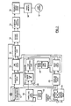
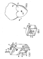
- a typical alarm system of the type under consideration includes at least one transmitter, of which transmitter 10, illustrated in figure 4 is an example thereof, for periodically transmitting through internal antenna 12 a radio frequency signal at approximately 50 megahertz, and monitor 14, illustrated in figure 3, for receiving through antenna 16 the radio frequency signal and providing means, as hereinafter explained, for indicating successful reception of the signal from that transmitter, or conversely, identifying the absence of reception of a signal from a given transmitter.
- Monitor 14 presents on its outer surface, as best illustrated in figure 3, conductive surface area 18 which transmits through local capacitive coupling an identification code or other programming to corresponding conductive surface area 20 located on the outer surface of transmitter 10, as best illustrated in figure 4, when same are brought together in interactive engagement, as will be hereinafter explained.
- Each transmitter 10 is programmed by corresponding monitor 14 with a digital programming code consisting of 1 bit, used for synchronizing the periodic transmissions of transmitter 10 to the reception window of monitor 14, followed by 8 bits, 7 bits being the unique system identification code for that monitor/transmitter(s) system, and the last bit being a zero, representing a tamper flag indicating if tamper switch 22 has been opened prematurely in removing transmitter 10 from an object, as will hereinafter be explained.
- a digital programming code consisting of 1 bit, used for synchronizing the periodic transmissions of transmitter 10 to the reception window of monitor 14, followed by 8 bits, 7 bits being the unique system identification code for that monitor/transmitter(s) system, and the last bit being a zero, representing a tamper flag indicating if tamper switch 22 has been opened prematurely in removing transmitter 10 from an object, as will hereinafter be explained.
- Transmitter 10 basically comprises means for detecting the programming code or other programming from monitor 14 through conductive surface area 20 including capacitive coupling amplifier circuit 24 and digital AM detector circuit 26, means for storing the unique 7 bit identification code and 1 bit tamper flag including 8 bit shift register 28, and means for recombining the output of 8 bit shift register 28 with the synchronizing code and transmitting same as a 50 megahertz radio frequency signal including synchronizing logic 30, for adding the synchronizing code to the output of 8 bit shift register 28, bi-phase encoder 32, 16.620 megahertz crystal oscillator 34, frequency tripler circuit 36, power amplifier 38, and antenna 12.
- Transmitter 10 is programmed by monitor 14 with the programming code when conductive surface area 20 is brought into interactive engagement with conductive surface area 18 of monitor 14. Programming between monitor 14 and transmitter 10 occurs through local capacitive coupling; the signal received by conductive surface area 20 is amplified by capacitive coupling amplifier circuit 24 and sent to digital AM detector circuit 26.
- the programming from monitor 14, amplified by capacitive coupling amplifier circuit 24, is in the form of an amplitude modulated signal having a 32 kilohertz carrier generated by 32 kilohertz crystal oscillator 40 of monitor 14, as best illustrated in figure 1.
- Transmitter 10 includes controlled low powered 32 kilohertz crystal oscillator 42 which continuously feeds divide-by-two circuit 44 reducing the frequency of 32 kilohertz crystal oscillator 42 to approximately 16 kilohertz.
- the 32 kilohertz signal from crystal oscillator 42 is fed together with the 16 kilohertz signal from divide-by two circuit 44 to digital AM detector circuit 26.
- Digital AM detector circuit 26 detects the 32 kilohertz programming signal counting transitions in the signal using flip-flops (not illustrated). This count for the detected signal is then compared to a similar count obtained from the 32 kilohertz signal generated by 32 kilohertz crystal oscillator 42: a successful comparison indicating that a valid programming signal is being received.
- the 16 kilohertz signal is used from divide-by-two circuit 44 to count two transitions of the detected programming signal in one cycle of the 16 kilohertz signal before the flip-flops are reset to zero to start the count again.
- two transactions of the detected programming signal and the 32 kilohertz output of crystal oscillator 42 are to be successfully counted and compared for the digital AM detector circuit 26 to produce a valid output.
- the programming signal is then fed into on/off logic circuit 46 and into identification program logic circuit 48.
- Identification program logic circuit 48 also receives input from on/off logic circuit 46 and 8 bit shift register 28.
- On/off logic circuit 46 outputs an "on” signal after successful reception of all the bits of the programming code from digital AM detector circuit 26. As long as an “off” signal is outputted from on/off logic circuit 46 identification program logic circuit 48 loads 8 bit shift register 28 with the incoming programming code, particularly the 7 bit identification code and 1 bit tamper flag. After receiving all of the programming code from digital AM detector circuit 26, on/off logic circuit 46 outputs an "on” signal, enabling identification program logic circuit 48 to recirculate the programming code stored in 8 bit shift register 28, consisting at this time of the 7 bit unique identification code and the 1 bit tamper flag indicator.
- on/off logic circuit 46 upon receiving the initial synchronizing or start bit of the programming code, energizes time delay circuit 50 which times the output of on/off logic circuit 46, identification program logic circuit 48, tamper flag logic circuit 52, synchronizing logic 30, and bi-phase encoder 32, enabling the programming code stored in transmitter 10 to be transmitted periodically, particularly every two seconds.
- the synchronizing or start bit of the programming code is used for synchronizing and starting the timing of transmitter 10, with monitor 14, as will be hereinafter explained.
- the 1 bit of the start bit must be longer than half a bit period for on/off logic circuit 46 to energize time delay circuit 50. Thereafter on/off logic circuit 46 samples the center of each bit period, outputting an "on" signal after the remaining 7 bit identification code and 1 bit tamper flag have been sampled.
- identification program logic circuit 48 is enabled by time delay circuit 50 to input the 7 bit identification code and 1 bit tamper flag from digital AM detector circuit 26, if on/off logic circuit 46 outputs and "off" signal, to 8 bit shift register, or, when on/off logic circuit 46 outputs and "on” signal, identification program logic circuit 48 recirculates the output of 8 bit shift register 28.
- time delay circuit 50 enables synchronizing logic 30 and bi-phase encoder 32.
- the output of 8 bit shift register 28, comprising the 7 bit identification code and 1 bit tamper flag, is recombined with the synchronization or start bit at synchronizing logic 30 to form the transmitted code, which, in most cases, is identical to the programming code received.
- the transmitted code is then encoded at bi-phase encoder 32 and modulated for FM transmission by 16.620 megahertz crystal oscillator 34.
- the resulting signal is sent to frequency tripler circuit 36, to power amplifier 38 and finally to antenna 12 for transmission.
- Antenna 12 in the preferred embodiment is particularly comprised of a loop antenna. To minimize points of poor reception by monitor 14 of the periodically transmitted code, however, antenna 12 can be combined with a wire antenna.
- the transmitted code is thus transmitted periodically, every 2 seconds, at 2048 baud.
- the start or synchronizing bit provided at synchronizing logic 30 actually consists of 4 bits - 1 bit preceded by three 0 bits.
- the resulting transmitted code is thus 12 bits long.
- Clip 54 is provided on the rear surface of transmitter 10, as best illustrated in figure 4 to attach and secure transmitter 10 to an object such as a child.
- clip 54 is provided with tamper switch 22.
- the opening or breaking of clip 54 causes tamper switch 22 to enable tamper flag logic circuit 52 to change the tamper flag bit located at 56 in 8 bit shift register 28 from zero to one.
- tamper flag logic circuit 52 By timing tamper flag logic circuit 52 with time delay circuit 50 the output of tamper switch 22 is read every two seconds, that is every time transmitter 10 transmits the transmitted code.
- transmitter 10a is in the form of a locket.
- Necklace 54a is provided for attaching and securing transmitter 10a to an object, particularly a child.
- Tamper switch 22a is provided where necklace 54a joins transmitter 10a and operates in the same manner as described hereinbefore.
- Transmitter 10a also provides exteriorly a conductive surface area 20a for receiving programing from monitor 14. Transmitter 10a operates identically to transmitter 10 as already outlined.
- Monitor 14 as best illustrated in figure 1, basically provides means to receive and monitor the periodically transmitted code from transmitter 10, including antenna 16, radio frequency receiver 58, and bi-phase decoder 60, means to identify the received signal, including identification check circuit 62, and identification program unit 64, means to note the presence or absence of an incoming signal from a given transmitter over a set period of time including on/off flag circuits 66, 68, logic timing circuits 70, 72, and counter circuits 74, 76, respectively, and means for providing visual and audio alarms as to the presence or absence of an incoming signal from transmitter 10 including audio logic circuit 78 and liquid crystal display circuit 80; the operation of all these circuits being controlled by monitor control logic circuit 82.
- Operator switch 84 in the preferred embodiment illustrated includes three positions, labelled “off”, “search”, and "guard”. The function of each of these positions shall be hereinafter explained.
- operator switch 84 dispatchs a signal to monitor control logic circuit 82, audio logic circuit 78 and liquid crystal display 80, indicating that monitor 14 is in the "guard" mode.
- the signal outputted by 32 kilohertz crystal oscillator 40 once powered on, enables logic timing circuits 70, 72, to be energized.
- Logic timing circuits 70, 72 are set one second out of synchronization with respect to one another, so that the signals outputted by logic timing circuits 70, 72, to monitor control logic circuit 82 are 1 second apart, enabling monitor control logic circuit 82 to determine which transmitter 10 is transmitting the transmitted code at that time.
- monitor control Iogic circuit 82 upon receiving an appropriate signal from logic timing circuits 70 or 72 that a particular transmitter 10 shall be transmitting the transmitted code, outputs a signal energizing radio frequency receiver 58, bi-phase decoder 60, and identification check circuit 62.
- logic timing circuits 70, 72 are timed such that monitor control logic circuit 82 energizes radio frequency receiver 58 1/32 of a second before the expected transmission from a given transmitter 10, and maintains the energization of same for 1/16 of a second.
- the incoming signal from transmitter 10 is then received and demodulated through radio frequency receiver 58, including antenna 16, and bi-phase decoder 60.
- the range of radio frequency receiver 58 can be adjusted by slide switch 92 which adjusts the gain of radio frequency receiver 58. Therefor, the distance that a transmitter 10 can be away from monitor 14 in order that a transmitted signal be received can be adjusted. It is to be appreciated that due to nature of transmitter antenna 12 and monitor antenna 16 and any intervening obstacles between monitor 14 and transmitter 10 the distance that transmitter 10 can be from monitor 14 is never a fixed measurement, but rather a variable range. For example, in the preferred embodiment a high setting on slide switch 92 would set the distance that transmitter 10 can be away from monitor 14 up to 1000 feet. Medium to low settings will set the range at various intermediate points from monitor 14.
- Bi-phase decoder 60 then outputs the received demodulated transmitted code to identification check circuit 62.
- the 7 bit identification code of the received transmitted code is compared to the stored 7 bit identification code from identification program unit 64.
- identification unit 64 is programmed with the 7 bit identification code at the time of manufacture, the identification code for the system being hard wired by means of jumper wires into identification program unit 64. Therefor, each monitor 14 programs its associated transmitters 10 with a unique 7 bit programming code.
- identification check circuit 62 Upon favorable comparison between the transmitted code and the programmed 7 bit unique identification code from identification program unit 64, and upon the tamper flag latch remaining unchanged, identification check circuit 62 transmits a valid comparison signal to monitor control logic circuit 82.
- Monitor control logic circuit 82 then transmits the valid comparison signal to appropriate logic timing circuit 70 or 72, depending upon which one is currently energized.
- On/off flag circuits 66, 68 indicate to monitor control logic circuit 82 the number of transmitters currently activated and programmed (in the preferred embodiment this is two) while timing circuits 70, 72 indicate to monitor control logic circuit 82 which transmitter 10 is transmitting the coded radio frequency signal at that time.
- monitor control logic circuit 82 determines which logic timing circuit 70 or 72, should the valid comparison signal be transmitted to.
- logic timing circuit 70 or 72 Upon receiving the valid comparison signal from monitor control logic circuit 82 logic timing circuit 70 or 72 transmits an appropriate signal to corresponding counter 74 or 76, respectively, resetting same.
- logic timing circuit 70 or 72 transmits an appropriate signal to corresponding counter 74 or 76 counting off one unsuccessful transmission from that transmitter 10. Each successive unsuccessful transmission from transmitter 10 causes a further count to be recorded by corresponding counter 74 or 76.
- counters 74 and 76 are set so that three consecutive transmission times are missed before counter 74 or 76 outputs a signal to audio warning circuit 78 energizing same, and liquid crystal display 80, to indicate visually which transmitter 10 failed to transmit, or transmitted an invalid transmitted code (as in the case of tamper flag bit at 56 in 8 bit shift register 28 of transmitter 10 being changed), so that the appropriate warnings are indicated.
- monitor 14 when operator switch 84 is in the "search” mode is similar to that as in the "guard” mode. In “search” mode, however, audio warning circuit 78 is enabled to give the appropriate audio indication upon reception of a successful signal by monitor 14 from transmitter 10.
- Logic timing circuits 70 or 72 upon receiving a valid comparison signal from monitor control logic circuit 82 transmit an appropriate signal to audio logic circuit 78 and liquid crystal display 80, for indicating successful reception of same, as well as reset counters 74 or 76.
- counters 74 or 76 have counted three consecutive failed transmissions, either by failing to receive the transmitted signal from transmitter 10 or receiving an invalid programming code, an appropriate signal is transmitted from counters 74 or 76 to audio warning circuit 78, ceasing the audio tone, which in the "search" mode indicates unsuccessful reception of a valid signal from a given transmitter 10.
- monitor 14 when monitor 14 is in "search” mode, monitor 14 is able to program transmitter 10 with the programming code, consisting of the 7 bit unique identification code, the tamper flag bit, and the start or synchronizing bit.
- radio frequency receiver 58 is energized by monitor control logic circuit 82 through logic timing circuits 70 or 72 to receive a transmitted signal from transmitter 10, the 7 bit unique identification code from identification program unit 64 is transmitted to program logic circuit 90 for transmission, together with the start or synchronizing bit and 1 bit tamper flag, by local capacitive coupling through conductive surface area 18 on monitor 14 to conductive surface area 20 on transmitter 10, when same are brought together in interactive engagement.
- monitor control logic circuit 82 upon receiving an indication from either logic timing circuit 70 or 72 to energize radio frequency receiver 58, instructs identification check circuit 62, bi-phase decoder 60 and program logic circuit 90 to transmit the programming code to transmitter 10.
- identification check circuit 62 upon receiving an indication from either logic timing circuit 70 or 72 to energize radio frequency receiver 58, instructs identification check circuit 62, bi-phase decoder 60 and program logic circuit 90 to transmit the programming code to transmitter 10.
- the 7 bit unique identification code in identification program unit 64 is inputted to identification check circuit 62 which, through two-way communication line 94, sends the code to bi-phase decoder 60 and onwards to program logic circuit 90.
- the final programming code is then transmitted through local capacitive coupling to transmitter 10 as hereinbefore described.
- monitor control circuit 82 energize program logic circuit 90, bi-phase decoder 60, and identification check circuit 62 to transmit the programming code upon receiving an appropriate energizing signal from logic timing circuit 70 or 72, ensures that transmitter 10 receives the synchronization bit, energizing time delay circuit 50, and ultimately causing transmitter 10 to transmit the transmitted code every two seconds in synchronization with the energization of radio frequency receiver 58 of monitor 14.
- transmitter 10 upon receiving the complete programming code, immediately begins transmitting and continues thereafter every two seconds.
- monitor control logic circuit 82 Upon receiving the transmitted code from transmitter 10, and upon receiving a valid comparison signal from identification check circuit 62, monitor control logic circuit 82 shall, in addition to transmitting a valid comparison signal to either logic timing circuit 70 or 72, program logic circuit 90 to turn “off” and shall instruct the corresponding on/off flag circuits 66 or 68 to turn “on”. On/off flag circuits 66, 68 then provide input to monitor control logic circuit 82 informing same as to the number of transmitters that have been energized and programmed.
- program logic circuit 90 transmits immediately after the programming code a series of "off" pulses, as will be hereinafter described for the "off" mode. If a valid programming code is received by receiver 58 of monitor 14 from transmitter 10 being programmed, then monitor control logic circuit 82 will turn “off” program logic circuit 90 discontinuing the transmission of the "off” pulses. If, however, transmitter 10 is programmed incorrectly identification check circuit 62 upon receiving and comparing the demodulated transmitted code from transmitter 10 will transmit an invalid comparison signal. Hence monitor control logic circuit 82 will not turn “off” program logic circuit 90, and "off” pulses will be fed into transmitter 10, turning same off. The next time logic timing circuit 70 or 72 energize monitor control logic circuit 82 the programming process shall be repeated until the transmitted code from transmitter 10 generates a valid comparison signal from identification check circuit 62, indicating reception of a correct programming code.
- monitor control logic circuit 82 instructs program logic circuit 90 to transmit "off" signals consisting of a series of 32 kilohertz clock bursts, to transmitter 10, again by local capacitive coupling through conductive surface area 18 on monitor 14 to conductive surface area 20 an transmitter 10, when same are brought together in interactive engagement.
- the duration of a burst is one quarter of a bit period at 2048 baud.
- a burst would consist of four 32 kilohertz clocks which is repeated every 1/2048 of a second.
- Monitor control logic circuit 82 of monitor 14 then receives from identification check circuit 62 an invalid comparison signal and relays same to on/off flag circuit 66 or 68 turning same "off”. Once both on/off flag circuits 66 and 68 are turned “off” then OR-gate 86 transmits an "off" signal to 32 kilohertz oscillator 40, effectively turning monitor 14 off.
- monitor 14 In operation, then, operator switch 84 of monitor 14 is first switched from the "off" position to the "search” mode. Monitor 14 is then ready to receive a transmitted radio frequency code from its associated transmitters 10, and more particularly, monitor 14 is now ready to program transmitters 10 with the 7 bit identification code, and 1 bit tamper flag, as described hereinbefore.
- conductive surface area 20 on transmitter 10 is brought into interactive engagement with conductive surface area 18 on monitor 14 so that the programming code can be fed into transmitter 10 through local capacitive coupling.
- on/off flag circuit 66 of monitor 14 Upon successful programming of one transmitter 10, on/off flag circuit 66 of monitor 14 outputs an "on” signal indicating to monitor control circuit 82 that one transmitter 10 has been programmed. Also, an "on” signal is outputted to liquid crystal display 80 so that the appropriate "Unit-On” shall be lit. In this particular example the "Unit 1-On" display 96 shall light up.
- audio logic circuit 78 Upon receiving a successful transmission from transmitter 10, audio logic circuit 78 shall provide the appropriate tone, every two seconds. Further, liquid crystal display 80 shall, at the same time, provide visual indication of successful reception of transmission through happy face 98.
- a second transmitter 10 can then be programmed in a similar manner.
- On/off flag circuit 68 will then output an "on" signal letting monitor control logic circuit 82 know that two transmitters have been programmed and further having liquid crystal display 80 indicate that a second transmitter has been programmed by the appropriate "Unit 2-On" display 100, being lit, and further, having happy face 102 flashing every two seconds every time a successful signal is received from the second transmitter.
- the transmitters can then be attached by clip 54 or necklace 54a, or any other suitable means, to a given object, person or animal, for example a child or a dog.
- Switching the monitor to "guard” mode causes audio logic circuit 78 to produce a warning audio signal only upon failure of receiving a given number of consecutive transmitted signals. Note, however, that liquid crystal display 80 causes happy faces 98, 102 to flash every time a successful signal is received from the corresponding transmitter in both "search” and “guard” modes.
- Slide switch 92 can be adjusted to set a range defining an area within which transmitters 10 can move freely without setting off an alarm.
- monitor 14 Upon moving a transmitter 10 outside the range setting the monitor will fail to receive the transmitted radio frequency signal. After failure of receiving three consecutive transmissions counter circuits 74 or 76 of monitor 14 instruct audio logic circuit 78 to provide the appropriate warning tone, and further, instructs liquid crystal display 80 to flash the "ALERT" indicator 104. Corresponding happy face 98 or 102 to the out of range transmitter 10 ceases flashing and remains lit continuously, indicating which transmitter 10 has gone outside the desired range setting.
- audio logic circuit 78 can be programmed to provide differing audio tones for the different transmitters.
- monitor 14 can then be used to locate the missing transmitter.
- monitor 14 can be moved until an appropriate tone is heard through audio logic circuit 78, indicating that the transmitter in now within the set range.
- tamper switch 22 and tamper flag logic circuit 52 to change the 1 bit tamper flag located at 56 in 8 bit shift register 28.
- This change is detected by monitor 14 as described hereinbefore and again results in the appropriate audio tone being sound by audio logic circuit 78 and the appropriate happy face 98, 102 remaining continuously lit to indicate which transmitter has become dislodged.
- liquid crystal display 80 causes the "TAMPER" indicator 106 to commence flashing distinguishing between an alarm for the transmitter going out of range, or the transmitter being tampered with.
Landscapes
- Physics & Mathematics (AREA)
- General Physics & Mathematics (AREA)
- Alarm Systems (AREA)
- Burglar Alarm Systems (AREA)
- Selective Calling Equipment (AREA)
Applications Claiming Priority (2)
| Application Number | Priority Date | Filing Date | Title |
|---|---|---|---|
| CA523462 | 1986-11-20 | ||
| CA000523462A CA1257657A (en) | 1986-11-20 | 1986-11-20 | Electronic alarm apparatus |
Publications (2)
| Publication Number | Publication Date |
|---|---|
| EP0268349A2 true EP0268349A2 (de) | 1988-05-25 |
| EP0268349A3 EP0268349A3 (de) | 1989-04-05 |
Family
ID=4134395
Family Applications (1)
| Application Number | Title | Priority Date | Filing Date |
|---|---|---|---|
| EP87306638A Withdrawn EP0268349A3 (de) | 1986-11-20 | 1987-07-28 | Elektronische Alarmvorrichtung |
Country Status (3)
| Country | Link |
|---|---|
| US (1) | US4792796A (de) |
| EP (1) | EP0268349A3 (de) |
| CA (1) | CA1257657A (de) |
Cited By (2)
| Publication number | Priority date | Publication date | Assignee | Title |
|---|---|---|---|---|
| EP0323041A3 (de) * | 1987-12-07 | 1989-10-18 | Barry M. Wolk | Sicherheitssystem für Kinder |
| BE1004724A3 (fr) * | 1991-04-16 | 1993-01-19 | Garot Jospeh | Dispositif de surveillance de la proximite d'un objet portatif. |
Families Citing this family (75)
| Publication number | Priority date | Publication date | Assignee | Title |
|---|---|---|---|---|
| ATE109292T1 (de) * | 1988-05-27 | 1994-08-15 | Digital Products Corp | Belegschafts-sicherheitsüberwachungsvorrichtung |
| US4918425A (en) * | 1988-07-25 | 1990-04-17 | Daniel E. Ely | Monitoring and locating system for an object attached to a transponder monitored by a base station having an associated ID code |
| US4899135A (en) * | 1988-12-05 | 1990-02-06 | Mehdi Ghahariiran | Child monitoring device |
| US5023595A (en) * | 1989-02-27 | 1991-06-11 | Bennett Charles S | Mail arrival signal system |
| US5032835A (en) * | 1989-04-24 | 1991-07-16 | Motorola, Inc. | Out of range indication for radio receivers |
| US4980671A (en) * | 1989-04-26 | 1990-12-25 | Guardian Technologies, Inc. | Remote confinement system with timed tamper signal reset |
| US5293160A (en) * | 1989-11-02 | 1994-03-08 | Nissan Motor Company, Ltd. | Keyless vehicle lock system with distance measuring |
| US5309144A (en) * | 1990-04-19 | 1994-05-03 | Lacombe David K | Proximity sensing security system |
| US5075670A (en) * | 1990-08-01 | 1991-12-24 | Digital Products Corporation | Personnel monitoring tag with tamper detection and secure reset |
| US5266944A (en) * | 1991-06-26 | 1993-11-30 | Bodyguard Technologies, Inc. | Electronic system and method for monitoring abusers for compliance with a protective order |
| US5196825A (en) * | 1991-12-16 | 1993-03-23 | Young James T | Personal security apparatus |
| US5966692A (en) * | 1992-05-12 | 1999-10-12 | Telemed Technologies International Corporation | Method and system for monitoring the heart of a patient |
| USD346125S (en) | 1992-12-11 | 1994-04-19 | Robert Cote | Personnel locator system |
| US5440294A (en) * | 1993-05-20 | 1995-08-08 | Mercier; Ellen L. | Mail delivery signal system |
| WO1994029824A1 (en) * | 1993-06-10 | 1994-12-22 | Direkt, Inc. | Preselected distance monitoring and locating system |
| US5589821A (en) * | 1994-12-13 | 1996-12-31 | Secure Technologies, Inc. | Distance determination and alarm system |
| US5646593A (en) * | 1995-02-02 | 1997-07-08 | Hewlett Electronics | Child proximity detector |
| US6012029A (en) * | 1995-09-29 | 2000-01-04 | Cirino; Sepideh S. | Voice activated system for locating misplaced items |
| SE9504479L (sv) * | 1995-12-14 | 1997-06-15 | Telia Ab | Anordning vid larmsystem |
| FI964417A7 (fi) * | 1996-06-14 | 1997-12-15 | Pasi Olavi Haavisto | Kannettavan laitteen unohtamisen estävä ja laitteen mukaanottamisesta muistuttava järjestelmä |
| USD392202S (en) | 1997-06-11 | 1998-03-17 | Mark Nitzberg | Combined transmitter and receiver for a portable computer alarm |
| US8464359B2 (en) | 1997-11-03 | 2013-06-11 | Intellectual Ventures Fund 30, Llc | System and method for obtaining a status of an authorization device over a network |
| US7280642B2 (en) * | 1997-11-03 | 2007-10-09 | Intellectual Ventures Fund 30, Llc | Status monitoring system utilizing an RFID monitoring system |
| US7088802B2 (en) | 1997-11-03 | 2006-08-08 | Light Elliott D | Method and apparatus for obtaining telephone status over a network |
| US7460859B2 (en) * | 1997-11-03 | 2008-12-02 | Light Elliott D | System and method for obtaining a status of an authorization device over a network for administration of theatrical performances |
| US6944465B2 (en) * | 1998-09-22 | 2005-09-13 | Polaris Wireless, Inc. | Estimating the location of a mobile unit based on the elimination of improbable locations |
| US6118380A (en) * | 1999-02-17 | 2000-09-12 | Gannon; Heather | Switch arrangement for child finder apparatus |
| MXPA01011736A (es) * | 1999-05-21 | 2003-09-04 | Koerner Ralph J | Sistema de identificacion para monitorear la presencia / ausencia de los miembros de un conjunto definido. |
| GB2353910A (en) * | 1999-09-03 | 2001-03-07 | Ibm | Asset tracking using local beacons |
| US6650241B2 (en) * | 1999-12-23 | 2003-11-18 | Harold G. Osborne | Child safety device |
| US7937042B2 (en) * | 2000-06-09 | 2011-05-03 | Dot Holdings, Llc | Animal training and tracking system using RF identification tags |
| US7042360B2 (en) * | 2000-06-09 | 2006-05-09 | Light Elliott D | Electronic tether for portable objects |
| US7064669B2 (en) * | 2000-06-09 | 2006-06-20 | Light Elliott D | Electronic tether for portable objects |
| FI117070B (fi) * | 2000-06-13 | 2006-05-31 | Seppo Luode | Valvonta- ja etsintäjärjestelmä sekä järjestelmään liitettävä turvamoduli |
| GB2367174B (en) * | 2000-09-25 | 2002-08-07 | Gadget Guard Ltd | A method and apparatus for security tagging |
| TW497744U (en) * | 2001-03-05 | 2002-08-01 | De-Shiang Huang | Touching and sensing alarm apparatus |
| US20050149226A1 (en) * | 2002-04-09 | 2005-07-07 | Ebox, Inc. | Warehousing system and method |
| DE10152830A1 (de) * | 2001-10-25 | 2003-05-08 | Philips Corp Intellectual Pty | Sicherungssystem für tragbare elektrische Geräte |
| US20050043886A1 (en) * | 2002-06-06 | 2005-02-24 | John Stevens | Delivery system and method for low visibilty conditions |
| US7433695B2 (en) * | 2002-11-18 | 2008-10-07 | Polaris Wireless, Inc. | Computationally-efficient estimation of the location of a wireless terminal based on pattern matching |
| JP2006508433A (ja) * | 2002-11-21 | 2006-03-09 | アンドレア・ルイージ・ドルセ・ペヒ | 電子離間警報システム及び位相同期生成処理 |
| GB0306898D0 (en) * | 2003-03-26 | 2003-04-30 | Bouchard Michel | Vehicle proximity alarm system |
| US20100033330A1 (en) * | 2003-04-09 | 2010-02-11 | Visible Assets, Inc. | Auditable security for cargo containers and other repositories |
| US7864053B2 (en) * | 2006-04-12 | 2011-01-04 | Visible Assets, Inc. | Visibility radio cap and network |
| US8378841B2 (en) * | 2003-04-09 | 2013-02-19 | Visible Assets, Inc | Tracking of oil drilling pipes and other objects |
| US8681000B2 (en) * | 2003-04-09 | 2014-03-25 | Visible Assets, Inc. | Low frequency inductive tagging for lifecycle management |
| US8026819B2 (en) * | 2005-10-02 | 2011-09-27 | Visible Assets, Inc. | Radio tag and system |
| US20070115132A1 (en) * | 2005-06-10 | 2007-05-24 | Visible Assets, Inc. | Tagging and communication system and methods for use therewith |
| WO2005002080A1 (en) * | 2003-05-28 | 2005-01-06 | Johnson Controls Technology Company | System and method for receiving data for training a trainable transmitter |
| US20050029345A1 (en) * | 2003-07-09 | 2005-02-10 | Paul Waterhouse | Integrated lock, drop-box and delivery system and method |
| US7268680B2 (en) * | 2003-10-06 | 2007-09-11 | Rf Technologies, Inc. | Electronic identification tag with electronic banding |
| US20050118905A1 (en) * | 2003-10-24 | 2005-06-02 | Mobilarm Pty Ltd | Maritime safety system |
| US7242301B2 (en) * | 2004-07-20 | 2007-07-10 | Visible Assets, Inc. | RF-enablement of products and receptacles therefor |
| EP1844455A4 (de) * | 2004-09-28 | 2009-02-11 | Visible Assets Inc | Hf-marken zum verfolgen und finden von reisetaschen |
| US7456418B1 (en) * | 2004-11-15 | 2008-11-25 | Visible Assets, Inc | RF-enablement of auditable storage for hazardous materials |
| US8643503B2 (en) | 2005-01-28 | 2014-02-04 | Kirill Mostov | Transportation security system and associated methods |
| US7990270B2 (en) | 2005-01-28 | 2011-08-02 | Kirsen Technologies Corporation Inc. | Transportation security system and associated methods |
| US7321290B2 (en) * | 2005-10-02 | 2008-01-22 | Visible Assets, Inc. | Radio tag and system |
| US9037098B2 (en) * | 2007-08-30 | 2015-05-19 | Binj Laboratories, Inc. | System and method for wrist band transmitter and system thereof |
| US20080001716A1 (en) * | 2006-07-03 | 2008-01-03 | Stevens John K | Method and Apparatus for Dynamically-Tuned Communication with One Among Myriad Tags |
| US20070069891A1 (en) * | 2005-09-28 | 2007-03-29 | Wallace David B | Child locator |
| US9069933B1 (en) | 2005-09-28 | 2015-06-30 | Visible Assets, Inc. | Secure, networked portable storage device |
| US20070120698A1 (en) * | 2005-11-29 | 2007-05-31 | Jordan Turk | System for monitoring the proximity of personal articles |
| JP2007316068A (ja) * | 2006-05-22 | 2007-12-06 | Polaris Wireless Inc | 無線端末の居場所の予測方法 |
| JP2007316070A (ja) * | 2006-05-22 | 2007-12-06 | Polaris Wireless Inc | 無線端末の居場所の予測方法 |
| WO2008070788A2 (en) | 2006-12-06 | 2008-06-12 | Kirsen Technologies Corporation | System and method for detecting dangerous objects and substances |
| US9430945B2 (en) * | 2006-12-20 | 2016-08-30 | Johnson Controls Technology Company | System and method for providing route calculation and information to a vehicle |
| EP2091784B1 (de) | 2006-12-20 | 2012-02-01 | Johnson Controls Technology Company | Fernanzeige-wiedergabesystem und -verfahren |
| WO2008091727A1 (en) * | 2007-01-23 | 2008-07-31 | Johnson Controls Technology Company | Mobile device gateway systems and methods |
| US8115472B2 (en) * | 2007-10-24 | 2012-02-14 | Kirsen Technologies Corporation Inc. | System and method for space control and remote monitoring |
| EP2223152A4 (de) | 2007-11-20 | 2011-04-20 | Kirsen Technologies Corp | Vorrichtung zur ferndetektion und überwachung verdeckter objekte |
| US9324230B2 (en) * | 2008-12-04 | 2016-04-26 | Gentex Corporation | System and method for configuring a wireless control system of a vehicle using induction field communication |
| JP5623287B2 (ja) | 2007-12-05 | 2014-11-12 | ジョンソン コントロールズテクノロジーカンパニーJohnson Controls Technology Company | 車両ユーザインターフェースシステム及び方法 |
| US20110021147A1 (en) * | 2009-07-21 | 2011-01-27 | Tout Walid R | System and method for determining connectivity status of short range wireless devices |
| US8896450B1 (en) * | 2009-12-23 | 2014-11-25 | Phillip H. Overbye | Fish strike alarm |
Family Cites Families (16)
| Publication number | Priority date | Publication date | Assignee | Title |
|---|---|---|---|---|
| US3336530A (en) * | 1964-10-14 | 1967-08-15 | Trak Microwave Corp | Direction finding system for hunting dogs |
| AU498573B2 (en) * | 1974-06-18 | 1979-03-15 | Aboyne Pty. Ltd. | Information transmission system |
| US4021807A (en) * | 1975-04-02 | 1977-05-03 | Texas Instruments Incorporated | Beacon tracking system |
| DE2647453A1 (de) * | 1976-10-21 | 1978-04-27 | Wolfgang Ing Grad Weil | Verfahren und vorrichtung zur ueberwachung einer beweglichen sache oder person |
| US4136338A (en) * | 1977-03-08 | 1979-01-23 | James D. Pauls & Associates, Ltd. | Perimeter alarm apparatus |
| US4162448A (en) * | 1977-03-16 | 1979-07-24 | Lewis Security Systems Limited | Radio signalling systems |
| US4337462A (en) * | 1977-12-27 | 1982-06-29 | Lemelson Jerome H | Theft detection system and method |
| DE2802075C3 (de) * | 1978-01-18 | 1980-11-13 | Compur-Electronic Gmbh, 8000 Muenchen | Verfahren zur Sicherung und Überwachung, insbesondere zur Personensicherung und -überwachung, sowie Anordnung zur Durchführung des Verfahrens |
| US4236068A (en) * | 1979-03-29 | 1980-11-25 | Walton Charles A | Personal identification and signaling system |
| US4305143A (en) * | 1979-08-08 | 1981-12-08 | Simms Larry L | Automatic man overboard sensor and rescue system |
| US4284985A (en) * | 1980-03-03 | 1981-08-18 | Vernon G. Heger | Stolen equipment recovery device |
| DE3150704C2 (de) * | 1981-12-21 | 1985-12-12 | Brown, Boveri & Cie Ag, 6800 Mannheim | Sende- und Empfangsschaltung für eine Einrichtung zur automatischen Identifizierung von Objekten und/oder Lebewesen |
| US4523184A (en) * | 1982-09-30 | 1985-06-11 | Sentrol, Inc. | Supervised wireless security system |
| US4549169A (en) * | 1982-12-06 | 1985-10-22 | Kelmar Marine Inc. | Personal ocean security system |
| FR2543715A1 (fr) * | 1983-03-30 | 1984-10-05 | Mayer Claude | Dispositif de surveillance declenchant une alarme en cas d'eloignement entre l'utilisateur et une personne, un animal ou un objet surveille |
| US4593273A (en) * | 1984-03-16 | 1986-06-03 | Narcisse Bernadine O | Out-of-range personnel monitor and alarm |
-
1986
- 1986-11-20 CA CA000523462A patent/CA1257657A/en not_active Expired
-
1987
- 1987-02-10 US US07/013,025 patent/US4792796A/en not_active Expired - Fee Related
- 1987-07-28 EP EP87306638A patent/EP0268349A3/de not_active Withdrawn
Cited By (2)
| Publication number | Priority date | Publication date | Assignee | Title |
|---|---|---|---|---|
| EP0323041A3 (de) * | 1987-12-07 | 1989-10-18 | Barry M. Wolk | Sicherheitssystem für Kinder |
| BE1004724A3 (fr) * | 1991-04-16 | 1993-01-19 | Garot Jospeh | Dispositif de surveillance de la proximite d'un objet portatif. |
Also Published As
| Publication number | Publication date |
|---|---|
| CA1257657A (en) | 1989-07-18 |
| EP0268349A3 (de) | 1989-04-05 |
| US4792796A (en) | 1988-12-20 |
Similar Documents
| Publication | Publication Date | Title |
|---|---|---|
| US4792796A (en) | Electronic alarm apparatus | |
| US4630035A (en) | Alarm system having alarm transmitter indentification codes and acoustic ranging | |
| US6806811B1 (en) | Infra-red perimeter alarm | |
| US4675656A (en) | Out-of-range personnel monitor and alarm | |
| US6236319B1 (en) | Personal monitoring system | |
| EP0231291B1 (de) | Elektronisches überwachungssystem und zugehörige sender-empfängeranlage | |
| WO1990013101A1 (en) | Remote confinement system with timed tamper detection reset | |
| CA1207052A (en) | Remote signalling apparatus | |
| CA2054751C (en) | Television signal detection apparatus | |
| GB2136251A (en) | Dedicated message matched filter | |
| KR0163607B1 (ko) | 원격 제어 시스템 | |
| KR100300160B1 (ko) | 무선통신을 이용한 인텔리전트 화재감지 시스템 | |
| DE69817435T2 (de) | Installierung und Überwachung von drahtlosen Sicherheitseinrichtungen mit reduzierter Energie | |
| GB2223380A (en) | Personnel location system | |
| GB2218245A (en) | Radio tag alarm system | |
| US5652573A (en) | Apparatus for the acquisition of events, in particular in carrier pigeon racing | |
| WO2004008181A2 (en) | An apparatus and method for a wireless locating device | |
| JP2840344B2 (ja) | 無線式警報システム | |
| KR920006889B1 (ko) | 무선식 방범 시스템 및 그 제어방법 | |
| JPH02902B2 (de) | ||
| JPS60225998A (ja) | ホ−ムセキユリテイセンサ−送信方式 | |
| JPH0787499B2 (ja) | ワイヤレス送信通報システム | |
| KR100432055B1 (ko) | 이격 감지 장치 | |
| JP2938742B2 (ja) | テレコントロール用送受信装置 | |
| JPH0935166A (ja) | 警報装置 |
Legal Events
| Date | Code | Title | Description |
|---|---|---|---|
| PUAI | Public reference made under article 153(3) epc to a published international application that has entered the european phase |
Free format text: ORIGINAL CODE: 0009012 |
|
| AK | Designated contracting states |
Kind code of ref document: A2 Designated state(s): AT BE CH DE ES FR GB GR IT LI LU NL SE |
|
| PUAL | Search report despatched |
Free format text: ORIGINAL CODE: 0009013 |
|
| AK | Designated contracting states |
Kind code of ref document: A3 Designated state(s): AT BE CH DE ES FR GB GR IT LI LU NL SE |
|
| 17P | Request for examination filed |
Effective date: 19890921 |
|
| STAA | Information on the status of an ep patent application or granted ep patent |
Free format text: STATUS: THE APPLICATION IS DEEMED TO BE WITHDRAWN |
|
| 18D | Application deemed to be withdrawn |
Effective date: 19910201 |
|
| RIN1 | Information on inventor provided before grant (corrected) |
Inventor name: WATERHOUSE, PAUL INGRAM Inventor name: HENSON, JOHN BOSANQUET Inventor name: BRADSHAW, LEROY |