EP0267837A1 - Waschmaschine mit Umlauf- und Entleerungspumpen - Google Patents
Waschmaschine mit Umlauf- und Entleerungspumpen Download PDFInfo
- Publication number
- EP0267837A1 EP0267837A1 EP87402391A EP87402391A EP0267837A1 EP 0267837 A1 EP0267837 A1 EP 0267837A1 EP 87402391 A EP87402391 A EP 87402391A EP 87402391 A EP87402391 A EP 87402391A EP 0267837 A1 EP0267837 A1 EP 0267837A1
- Authority
- EP
- European Patent Office
- Prior art keywords
- tank
- washing machine
- pump
- drive
- recycling
- Prior art date
- Legal status (The legal status is an assumption and is not a legal conclusion. Google has not performed a legal analysis and makes no representation as to the accuracy of the status listed.)
- Withdrawn
Links
Images


Classifications
-
- D—TEXTILES; PAPER
- D06—TREATMENT OF TEXTILES OR THE LIKE; LAUNDERING; FLEXIBLE MATERIALS NOT OTHERWISE PROVIDED FOR
- D06F—LAUNDERING, DRYING, IRONING, PRESSING OR FOLDING TEXTILE ARTICLES
- D06F37/00—Details specific to washing machines covered by groups D06F21/00 - D06F25/00
- D06F37/26—Casings; Tubs
- D06F37/261—Tubs made by a specially selected manufacturing process or characterised by their assembly from elements
- D06F37/262—Tubs made by a specially selected manufacturing process or characterised by their assembly from elements made of plastic material, e.g. by injection moulding
-
- D—TEXTILES; PAPER
- D06—TREATMENT OF TEXTILES OR THE LIKE; LAUNDERING; FLEXIBLE MATERIALS NOT OTHERWISE PROVIDED FOR
- D06F—LAUNDERING, DRYING, IRONING, PRESSING OR FOLDING TEXTILE ARTICLES
- D06F37/00—Details specific to washing machines covered by groups D06F21/00 - D06F25/00
- D06F37/26—Casings; Tubs
- D06F37/261—Tubs made by a specially selected manufacturing process or characterised by their assembly from elements
- D06F37/263—Tubs made by a specially selected manufacturing process or characterised by their assembly from elements assembled from at least two elements connected to each other; Connecting or sealing means therefor
-
- D—TEXTILES; PAPER
- D06—TREATMENT OF TEXTILES OR THE LIKE; LAUNDERING; FLEXIBLE MATERIALS NOT OTHERWISE PROVIDED FOR
- D06F—LAUNDERING, DRYING, IRONING, PRESSING OR FOLDING TEXTILE ARTICLES
- D06F37/00—Details specific to washing machines covered by groups D06F21/00 - D06F25/00
- D06F37/26—Casings; Tubs
- D06F37/267—Tubs specially adapted for mounting thereto components or devices not provided for in preceding subgroups
- D06F37/268—Tubs specially adapted for mounting thereto components or devices not provided for in preceding subgroups for suspension devices
-
- D—TEXTILES; PAPER
- D06—TREATMENT OF TEXTILES OR THE LIKE; LAUNDERING; FLEXIBLE MATERIALS NOT OTHERWISE PROVIDED FOR
- D06F—LAUNDERING, DRYING, IRONING, PRESSING OR FOLDING TEXTILE ARTICLES
- D06F39/00—Details of washing machines not specific to a single type of machines covered by groups D06F9/00 - D06F27/00
- D06F39/08—Liquid supply or discharge arrangements
- D06F39/083—Liquid discharge or recirculation arrangements
- D06F39/085—Arrangements or adaptations of pumps
-
- D—TEXTILES; PAPER
- D06—TREATMENT OF TEXTILES OR THE LIKE; LAUNDERING; FLEXIBLE MATERIALS NOT OTHERWISE PROVIDED FOR
- D06F—LAUNDERING, DRYING, IRONING, PRESSING OR FOLDING TEXTILE ARTICLES
- D06F2103/00—Parameters monitored or detected for the control of domestic laundry washing machines, washer-dryers or laundry dryers
- D06F2103/44—Current or voltage
- D06F2103/48—Current or voltage of the motor driving the pump
Definitions
- the present invention relates to a washing machine with recycling and drain pumps.
- a washing machine usually comprises in the lowest part of its tank, a hydraulic drain circuit comprising a depression or liquid collection well provided with a liquid discharge pipe to which is attached an inlet pipe d '' a drain pump whose outlet is extended outwards by a drain pipe.
- a hydraulic drain circuit comprising a depression or liquid collection well provided with a liquid discharge pipe to which is attached an inlet pipe d '' a drain pump whose outlet is extended outwards by a drain pipe.
- the aim of the present invention is to avoid these drawbacks and makes it possible to produce an economical washing machine provided with a drain pump and a recycling pump which makes it possible to eliminate losses of detergents introduced into the device.
- a washing machine with recycling and drain pumps comprises a tank, the structure of which comprises an assembly comprising a drain pump and a liquid recycling pump, in which shafts of turbines of these pumps are supported by a lower part of a cover of this tank and of the bodies of the chambers of these pumps are directly formed by a lower part of a body of this tank.
- a washing machine 1 according to an exemplary embodiment of the invention, illustrated in FIGS. 1 and 2 comprises a body 2, a tank 3, a washing drum 4, a set for draining and recycling liquid 5, the system driving the drum 4 in rotation and the other accessories of known types not being shown.
- the tank 3 is a tank made of a molded or injected synthetic material, formed of a tank body 6 and a tank cover 7.
- the tank 3 has a structure which includes an assembly comprising 5 of the drain pump 8 and of the liquid recycling pump 9.
- the drain pump 8 comprises (FIGS. 2, 3, 4) a turbine chamber 10 provided with an axial inlet 11 and a lateral outlet 12, a turbine 13 fixed to an inner end a free rotating shaft 14, the outer end of which carries a drive receiving pulley 15 and the recycling pump 9 comprises (FIGS. 2, 3, 5) a turbine chamber 16 provided with an axial inlet 17 and d 'a side outlet 18, a turbine 19 fixed to an inner end of a free-rotating shaft 20, the outer end of which carries a drive receiving pulley 21.
- the separate chambers of turbines 10 and 16 of these pumps 8 and 9 are axially spaced and parallel.
- the assembly including 5 of drain 8 and recycling 9 pumps includes a common intake chamber 23 into which the respective inlets 11 and 17 of these pumps open.
- the free rotating shafts 14 and 20 of the turbines 13 and 19 of the drain 8 and recycling 9 pumps are spaced, parallel and are supported by a lower part 24 of the tank cover 7 which serves as their supports while the bodies of the chambers turbines 10 and 16 are directly formed in a lower part 25 of the tank body 6 of the tank 3 of the washing machine 1.
- the common inlet chamber 23 of the drain 8 and recycling 9 pumps which is formed in a lower part of the tank 3, also constitutes a liquid collection well from this tank 3.
- the lower part 24 of the tank cover 7 which serves as supports for the shafts 14 and 20 of the turbines of the drain 8 and recycling pumps 9 also closes the bodies of the turbine chambers 10 and 16 and therefore constitutes covers for these turbine chamber bodies 10 and 16.
- O-rings 27, 28, 29 are mounted between the tank body 6 and the cover of tank 7, respectively around the body tank 6, turbine chamber 10 and turbine chamber 16 to ensure liquid tightness of the tank 3 and that of these turbine chambers 10 and 16 of the drain 8 and recycling pumps 9.
- the shafts of turbines 14 and 20 are mounted to rotate freely in bearings 30, 31, 32 and made liquid-tight by shaft seals 33, 34 and abutment seals 35, 36.
- the two drive pulleys 15 and 21 turbines 13 and 19 of the drain pumps 8 and 9 are offset in their axial direction, with respect to each other, by a predetermined distance D and successively driven by a system 37 comprising a drive biconic drive pulley 38 slidingly mounted on a sheath 39 secured to a shaft 40 of a drive motor 41 fixed on the lower part 24 of the tank cover 7 which serves as its support.
- the sliding biconical drive pulley 38 comprises a hub 42 provided with a heart-grooved rod 43 intended to receive a lug 44 fixed on the sheath 39.
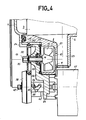
- the heart-grooved rod 43 and the lug 44 determine an amplitude A of the displacement axial of the sliding biconical drive pulley 38 on this sleeve 39, which is equal to the offset D of the receiving drive pulleys 15, 21 in their axial direction so that in an outgoing position (FIG. 5) the outer conical part of the pulley biconical drive 38 engages in drive with the receiving pulley 21 of the recycling pump 9 and in a re-entrant position ( Figure 4) the inner conical portion of the biconical drive pulley 38 engages in drive with the receiving pulley 15 of the drain pump 8.
- a helical spring 46 mounted between the free end of the hub 42 with a cane with a heart groove 43 and a protruding flange from the inner end of the sleeve 39 provides an automatic return. eu of the biconical driving pulley 38 in its outgoing position which puts it in drive engagement with the receiving pulley driving the recycling pump 9 (FIG. 5).
- the sliding biconical drive pulley 38 is pushed into its re-entrant position (FIG. 4) by a finger 47 pivoting about an axis 48, actuated by an electromagnetic control coil with a core 49 when the latter is energized electric by a not shown programmer of the washing machine 1.
- flanges 50 and 51 made of a material with a high coefficient of friction such as an elastomer, which increase the adhesion of the receiving pulleys 15 and 21 with the driving pulley. 38 when engaged.
- the outlet 12 of the drain pump 8 formed directly in the lower part 25 of the tank body 6 is connected to a drain pipe or cane 52 which extends it outside the washing machine 1 while the outlet 18 of the drain pump 9 also produced and directly in the lower part 25 of the body of tank 6 is extended towards an upper part of tank 3 by a passage 54 and a groove 55 (FIGS. 2, 3) directly formed in the tank cover 7.
- the groove 55 is closed in a liquid tight manner by a band 56.
- the groove 55 opens into the tank 3 at a level located above the level of the liquid collection well formed by the common inlet chamber 23 of the pumps 8 and 9.
- the turbine chambers of the drain pumps 8 and recycling 9, their common inlet chamber 23, their outlets 12, 18 and their extension pipes 54, 55 thus form an integral part respectively of the tank body 6 and of the tank cover 7 and are produced simultaneously with the latter during their manufacture by molding or by injection of a synthetic material. All the usual and expensive storage and assembly of "pump-tub" connecting pipes in known washing machines is therefore avoided.
- the electromagnetic control coil 49 is switched off electrically by the programmer of the washing machine 1, the helical spring 46 pushes the biconical drive pulley 38 in its outgoing position ( Figure 5) and triggers the operation of the recycling pump 9.
- the water and detergents accumulated in the bottom of the tank 3 or collection well in other words in the common inlet chamber 23 are then drawn and returned, through the outlet 18 of the recycling pump 9, the passage 54 and the closed groove 55-56, in the tank 3 at a level above the common intake chamber 23.
- the electromagnetic control coil 49 is energized by the programmer, the finger 47 actuated by the core of the coil 49 pushes the sliding biconical drive pulley 38 from its position outgoing in its re-entering position, thereby interrupts the operation of the recycling pump 9 and triggers that of the drain pump 8.
- the liquid in the tank 3 is discharged to the outside of the washing machine 1, via the outlet 12 of the drain pump 8 and the drain hose or pipe 52.
- the electromagnetic control coil 49 is de-energized by the programmer and the sliding drive pulley 38 is pushed back from its re-entrant position to its position outgoing to be again engaged in drive with the recycling pump.
Applications Claiming Priority (2)
| Application Number | Priority Date | Filing Date | Title |
|---|---|---|---|
| FR8614979A FR2605652B1 (fr) | 1986-10-28 | 1986-10-28 | Lave-linge a pompes de recyclage et de vidange |
| FR8614979 | 1986-10-28 |
Publications (1)
| Publication Number | Publication Date |
|---|---|
| EP0267837A1 true EP0267837A1 (de) | 1988-05-18 |
Family
ID=9340277
Family Applications (1)
| Application Number | Title | Priority Date | Filing Date |
|---|---|---|---|
| EP87402391A Withdrawn EP0267837A1 (de) | 1986-10-28 | 1987-10-23 | Waschmaschine mit Umlauf- und Entleerungspumpen |
Country Status (2)
| Country | Link |
|---|---|
| EP (1) | EP0267837A1 (de) |
| FR (1) | FR2605652B1 (de) |
Cited By (6)
| Publication number | Priority date | Publication date | Assignee | Title |
|---|---|---|---|---|
| EP0500144A1 (de) * | 1988-02-01 | 1992-08-26 | Bosch-Siemens Hausgeräte GmbH | Waschmaschine mit einem Laugenbehälter |
| EP0534381A1 (de) * | 1991-09-27 | 1993-03-31 | Whirlpool Europe B.V. | Entleerungsvorrichtung für Waschmaschinen oder dergleichen |
| FR2818669A1 (fr) * | 2000-12-26 | 2002-06-28 | Ciapem | Dispositif permettant de realiser une recirculation de fluide destine notamment a un lave-linge |
| FR2818671A1 (fr) * | 2000-12-26 | 2002-06-28 | Ciapem | Dispositif de filtration pour un lave-linge |
| EP2631345A1 (de) | 2012-02-27 | 2013-08-28 | Electrolux Home Products Corporation N.V. | Waschwanneneinheit und Waschmaschine |
| EP2631343A1 (de) | 2012-02-27 | 2013-08-28 | Electrolux Home Products Corporation N.V. | Waschwanneneinheit und Waschmaschine |
Citations (8)
| Publication number | Priority date | Publication date | Assignee | Title |
|---|---|---|---|---|
| US2880740A (en) * | 1956-12-28 | 1959-04-07 | Waste King Corp | Dishwasher with vibration-preventing motor and impeller mount |
| FR1336973A (fr) * | 1962-10-03 | 1963-09-06 | Constructa Werke Gmbh | Pompe double destinée particulièrement à une machine à laver et à centrifuger, fonctionnant en courant continu |
| DE1653683A1 (de) * | 1968-02-24 | 1971-08-05 | Bosch Hausgeraete Gmbh | Umwaelzpumpe und Abwasserpumpe |
| FR2085269A7 (de) * | 1970-04-03 | 1971-12-24 | Stierlen Werke Ag | |
| FR2425228A1 (fr) * | 1978-05-09 | 1979-12-07 | Indesit | Cuve pour machine a laver la vaisselle |
| EP0026018A1 (de) * | 1979-09-19 | 1981-04-01 | Constructions Electro-Mecaniques D'amiens | Maschine zum Waschen und Schleudern von Wäsche, deren Trommel mittels eines untergetauchten Riemens angetrieben wird |
| FR2528690A3 (fr) * | 1982-06-21 | 1983-12-23 | Indesit | Disposition de la roue de pompe et du moteur electrique sur un lave-vaisselle |
| DE3443166A1 (de) * | 1984-11-27 | 1986-05-28 | Miele & Cie GmbH & Co, 4830 Gütersloh | Geschirrspuelmaschine mit einer entleerungspumpe und einem rueckschlagventil |
-
1986
- 1986-10-28 FR FR8614979A patent/FR2605652B1/fr not_active Expired
-
1987
- 1987-10-23 EP EP87402391A patent/EP0267837A1/de not_active Withdrawn
Patent Citations (8)
| Publication number | Priority date | Publication date | Assignee | Title |
|---|---|---|---|---|
| US2880740A (en) * | 1956-12-28 | 1959-04-07 | Waste King Corp | Dishwasher with vibration-preventing motor and impeller mount |
| FR1336973A (fr) * | 1962-10-03 | 1963-09-06 | Constructa Werke Gmbh | Pompe double destinée particulièrement à une machine à laver et à centrifuger, fonctionnant en courant continu |
| DE1653683A1 (de) * | 1968-02-24 | 1971-08-05 | Bosch Hausgeraete Gmbh | Umwaelzpumpe und Abwasserpumpe |
| FR2085269A7 (de) * | 1970-04-03 | 1971-12-24 | Stierlen Werke Ag | |
| FR2425228A1 (fr) * | 1978-05-09 | 1979-12-07 | Indesit | Cuve pour machine a laver la vaisselle |
| EP0026018A1 (de) * | 1979-09-19 | 1981-04-01 | Constructions Electro-Mecaniques D'amiens | Maschine zum Waschen und Schleudern von Wäsche, deren Trommel mittels eines untergetauchten Riemens angetrieben wird |
| FR2528690A3 (fr) * | 1982-06-21 | 1983-12-23 | Indesit | Disposition de la roue de pompe et du moteur electrique sur un lave-vaisselle |
| DE3443166A1 (de) * | 1984-11-27 | 1986-05-28 | Miele & Cie GmbH & Co, 4830 Gütersloh | Geschirrspuelmaschine mit einer entleerungspumpe und einem rueckschlagventil |
Cited By (9)
| Publication number | Priority date | Publication date | Assignee | Title |
|---|---|---|---|---|
| EP0500144A1 (de) * | 1988-02-01 | 1992-08-26 | Bosch-Siemens Hausgeräte GmbH | Waschmaschine mit einem Laugenbehälter |
| EP0534381A1 (de) * | 1991-09-27 | 1993-03-31 | Whirlpool Europe B.V. | Entleerungsvorrichtung für Waschmaschinen oder dergleichen |
| FR2818669A1 (fr) * | 2000-12-26 | 2002-06-28 | Ciapem | Dispositif permettant de realiser une recirculation de fluide destine notamment a un lave-linge |
| FR2818671A1 (fr) * | 2000-12-26 | 2002-06-28 | Ciapem | Dispositif de filtration pour un lave-linge |
| EP2631345A1 (de) | 2012-02-27 | 2013-08-28 | Electrolux Home Products Corporation N.V. | Waschwanneneinheit und Waschmaschine |
| EP2631343A1 (de) | 2012-02-27 | 2013-08-28 | Electrolux Home Products Corporation N.V. | Waschwanneneinheit und Waschmaschine |
| WO2013127743A2 (en) | 2012-02-27 | 2013-09-06 | Electrolux Home Products Corporation N.V. | Washing tub unit and washing machine |
| WO2013127739A2 (en) | 2012-02-27 | 2013-09-06 | Electrolux Home Products Corporation N.V. | Washing tub unit and washing machine |
| WO2013127739A3 (en) * | 2012-02-27 | 2014-08-28 | Electrolux Home Products Corporation N.V. | Washing tub unit and washing machine |
Also Published As
| Publication number | Publication date |
|---|---|
| FR2605652B1 (fr) | 1989-03-31 |
| FR2605652A1 (fr) | 1988-04-29 |
Similar Documents
| Publication | Publication Date | Title |
|---|---|---|
| EP0267837A1 (de) | Waschmaschine mit Umlauf- und Entleerungspumpen | |
| EP2312042A1 (de) | Waschmaschine mit einem Hydraulikschaltkreis zur Wasserverteilung, der mit zwei Wasserumwälzpumpen ausgestattet ist | |
| FR2556952A1 (fr) | Lave-vaisselle a usage menager | |
| EP0506534B1 (de) | Entnahmekopf für Flüssigkeitsproben | |
| FR2718494A1 (fr) | Pompe à condensat pour un sèche-linge. | |
| EP2434041B1 (de) | Waschmaschine mit einem Hydraulikkreislauf zur Wasserverteilung | |
| EP0110482A1 (de) | Waschmaschine für Wäsche mit im Behälterunterteil anfangender Ablaufleitung | |
| EP2312045A1 (de) | Waschmaschine mit einem Hydraulikschaltkreis zur Wasserverteilung, der mit einer Entlüftungsvorrichtung ausgestattet ist, die an eine Zone mit Flüssigkeitsleitung zu einem Waschtank angeschlossen ist | |
| EP0541464B1 (de) | Durchlaufwaschmaschine für Textilien oder dergleichen | |
| EP0214039B1 (de) | Trommel mit eingebauten Achsen und mit einer solchen Trommel ausgerüstete Waschmaschine | |
| FR2517194A1 (fr) | Lave-vaisselle utilisant une quantite d'eau limitee | |
| FR2599395A3 (fr) | Collecteur de reception du liquide de lavage pour machines lave-linge | |
| FR2785302A1 (fr) | Systeme automatique d'alimentation d'une machine a laver le linge en produit de lavage, et machine equipee d'un tel systeme | |
| FR2505209A1 (fr) | Cuve de traitement d'une matiere presentant une nature permeable a un fluide | |
| BE503502A (de) | ||
| FR2605362A1 (fr) | Pompe, en particulier pour lave-vaisselle et machines a laver | |
| FR2666725A1 (fr) | Porte de lavage d'une machine a baratter. | |
| WO1990014789A1 (fr) | Dispositif de distribution et de dosage pour des installations de lavage ou de nettoyage | |
| FR2818669A1 (fr) | Dispositif permettant de realiser une recirculation de fluide destine notamment a un lave-linge | |
| FR2648697A1 (fr) | Moulinet rotatif pour machine a laver la vaisselle | |
| FR2470268A1 (fr) | Perfectionnements aux pompes de transvasement a tube plongeur et a turbine immergee | |
| BE506640A (de) | ||
| CH339169A (fr) | Machine à laver | |
| FR2619836A1 (fr) | Procede et dispositif pour l'evacuation et l'alimentation des eaux dans un tambour etanche a l'eau | |
| FR2479849A1 (fr) | Appareil pour produire un biogaz |
Legal Events
| Date | Code | Title | Description |
|---|---|---|---|
| PUAI | Public reference made under article 153(3) epc to a published international application that has entered the european phase |
Free format text: ORIGINAL CODE: 0009012 |
|
| AK | Designated contracting states |
Kind code of ref document: A1 Designated state(s): AT BE CH DE ES FR GB GR IT LI LU NL SE |
|
| STAA | Information on the status of an ep patent application or granted ep patent |
Free format text: STATUS: THE APPLICATION IS DEEMED TO BE WITHDRAWN |
|
| 18D | Application deemed to be withdrawn |
Effective date: 19881119 |
|
| RIN1 | Information on inventor provided before grant (corrected) |
Inventor name: BURGEL, CHRISTIAN Inventor name: SAVARY, HENRI |