EP0026018A1 - Maschine zum Waschen und Schleudern von Wäsche, deren Trommel mittels eines untergetauchten Riemens angetrieben wird - Google Patents
Maschine zum Waschen und Schleudern von Wäsche, deren Trommel mittels eines untergetauchten Riemens angetrieben wird Download PDFInfo
- Publication number
- EP0026018A1 EP0026018A1 EP80200866A EP80200866A EP0026018A1 EP 0026018 A1 EP0026018 A1 EP 0026018A1 EP 80200866 A EP80200866 A EP 80200866A EP 80200866 A EP80200866 A EP 80200866A EP 0026018 A1 EP0026018 A1 EP 0026018A1
- Authority
- EP
- European Patent Office
- Prior art keywords
- tank
- drum
- washing machine
- motor
- machine according
- Prior art date
- Legal status (The legal status is an assumption and is not a legal conclusion. Google has not performed a legal analysis and makes no representation as to the accuracy of the status listed.)
- Granted
Links
Images


Classifications
-
- D—TEXTILES; PAPER
- D06—TREATMENT OF TEXTILES OR THE LIKE; LAUNDERING; FLEXIBLE MATERIALS NOT OTHERWISE PROVIDED FOR
- D06F—LAUNDERING, DRYING, IRONING, PRESSING OR FOLDING TEXTILE ARTICLES
- D06F37/00—Details specific to washing machines covered by groups D06F21/00 - D06F25/00
- D06F37/20—Mountings, e.g. resilient mountings, for the rotary receptacle, motor, tub or casing; Preventing or damping vibrations
- D06F37/206—Mounting of motor
-
- D—TEXTILES; PAPER
- D06—TREATMENT OF TEXTILES OR THE LIKE; LAUNDERING; FLEXIBLE MATERIALS NOT OTHERWISE PROVIDED FOR
- D06F—LAUNDERING, DRYING, IRONING, PRESSING OR FOLDING TEXTILE ARTICLES
- D06F37/00—Details specific to washing machines covered by groups D06F21/00 - D06F25/00
-
- D—TEXTILES; PAPER
- D06—TREATMENT OF TEXTILES OR THE LIKE; LAUNDERING; FLEXIBLE MATERIALS NOT OTHERWISE PROVIDED FOR
- D06F—LAUNDERING, DRYING, IRONING, PRESSING OR FOLDING TEXTILE ARTICLES
- D06F37/00—Details specific to washing machines covered by groups D06F21/00 - D06F25/00
- D06F37/26—Casings; Tubs
- D06F37/261—Tubs made by a specially selected manufacturing process or characterised by their assembly from elements
- D06F37/262—Tubs made by a specially selected manufacturing process or characterised by their assembly from elements made of plastic material, e.g. by injection moulding
-
- D—TEXTILES; PAPER
- D06—TREATMENT OF TEXTILES OR THE LIKE; LAUNDERING; FLEXIBLE MATERIALS NOT OTHERWISE PROVIDED FOR
- D06F—LAUNDERING, DRYING, IRONING, PRESSING OR FOLDING TEXTILE ARTICLES
- D06F37/00—Details specific to washing machines covered by groups D06F21/00 - D06F25/00
- D06F37/26—Casings; Tubs
- D06F37/264—Tubs provided with reinforcing structures, e.g. ribs, inserts, braces
-
- D—TEXTILES; PAPER
- D06—TREATMENT OF TEXTILES OR THE LIKE; LAUNDERING; FLEXIBLE MATERIALS NOT OTHERWISE PROVIDED FOR
- D06F—LAUNDERING, DRYING, IRONING, PRESSING OR FOLDING TEXTILE ARTICLES
- D06F37/00—Details specific to washing machines covered by groups D06F21/00 - D06F25/00
- D06F37/26—Casings; Tubs
- D06F37/267—Tubs specially adapted for mounting thereto components or devices not provided for in preceding subgroups
- D06F37/269—Tubs specially adapted for mounting thereto components or devices not provided for in preceding subgroups for the bearing of the rotary receptacle
-
- D—TEXTILES; PAPER
- D06—TREATMENT OF TEXTILES OR THE LIKE; LAUNDERING; FLEXIBLE MATERIALS NOT OTHERWISE PROVIDED FOR
- D06F—LAUNDERING, DRYING, IRONING, PRESSING OR FOLDING TEXTILE ARTICLES
- D06F37/00—Details specific to washing machines covered by groups D06F21/00 - D06F25/00
- D06F37/30—Driving arrangements
-
- F—MECHANICAL ENGINEERING; LIGHTING; HEATING; WEAPONS; BLASTING
- F16—ENGINEERING ELEMENTS AND UNITS; GENERAL MEASURES FOR PRODUCING AND MAINTAINING EFFECTIVE FUNCTIONING OF MACHINES OR INSTALLATIONS; THERMAL INSULATION IN GENERAL
- F16C—SHAFTS; FLEXIBLE SHAFTS; ELEMENTS OR CRANKSHAFT MECHANISMS; ROTARY BODIES OTHER THAN GEARING ELEMENTS; BEARINGS
- F16C23/00—Bearings for exclusively rotary movement adjustable for aligning or positioning
- F16C23/10—Bearings, parts of which are eccentrically adjustable with respect to each other
-
- F—MECHANICAL ENGINEERING; LIGHTING; HEATING; WEAPONS; BLASTING
- F16—ENGINEERING ELEMENTS AND UNITS; GENERAL MEASURES FOR PRODUCING AND MAINTAINING EFFECTIVE FUNCTIONING OF MACHINES OR INSTALLATIONS; THERMAL INSULATION IN GENERAL
- F16C—SHAFTS; FLEXIBLE SHAFTS; ELEMENTS OR CRANKSHAFT MECHANISMS; ROTARY BODIES OTHER THAN GEARING ELEMENTS; BEARINGS
- F16C2340/00—Apparatus for treating textiles
Definitions
- the invention relates to a washing machine and spin dryer comprising a tank for receiving the washing or rinsing water, inside which can rotate a laundry drum of substantially horizontal axis supported by at least one shaft mounted in a bearing housed in the tank wall, an electric motor fixed to the tank driving the drum by means of a belt tensioned between a drive pulley and a take-up pulley secured to the drum, the drive and take-up pulleys and the belt being located inside the tank and bathing at least partially in the washing or rinsing water.
- the motor is generally off-center and mounted on the side of the tank where the pulley is located. receptor.
- This location of the engine means that its mass must be balanced by a counterweight fixed to the tank, so that the center of gravity of the washer unit constituted by the drum, its pulley, the tank and the engine, is constantly in the plane of symmetry perpendicular to the 'axis of rotation of the drum, and this, regardless of the filling of water in the tank.
- the invention consists in combining the two constructions mentioned above.
- the tank in a washing machine with drum drive by belt and submerged pulleys, as described in the preamble above, the tank is arranged in a body to which it is linked in an elastic and damped manner, the motor being fixed so that the center of gravity of the washer unit constituted by the drum, its pulley, the tank and the motor is substantially in the plane of symmetry perpendicular to the axis of the drum.
- a substantially equidistant plane of the vertical flanges of the tank is called plane of symmetry, even if said flanges do not have exactly symmetrical shapes.
- the invention therefore makes it possible to save space between the tank and the body of the machine, and to eliminate the balancing mass of the engine, thus remedying two faults of machines of the type with an elastically suspended tank.
- V-belt or with multiple grooves, or with teeth , subjected to a tension between the motor and receiver axes of approximately 10 daN, adheres sufficiently to its pulleys not to slip when the engine starts, that is to say at the moment when the transmitted torque is maximum.
- materials based on elastomers such as neoprenes, or based on thermoplastic rubbers such as polyesters or polyurethanes, can be used to constitute a belt having good stability of its initial characteristics of breaking strength, the elongation, in tearing, of its modulus of elasticity, having good resistance to bending, to abrasion and a good coefficient of friction, on metals for example.
- the frame of such a belt can for example be made of polyester fibers or glass fibers. It should also be noted that when using a toothed belt, the drive pulley, itself toothed, cannot slide in the belt, regardless of the environment in which they are immersed.
- the drive pulley is mounted on the shaft of the drive motor parallel to the axis of the drum and passing through the tank wall at a point between the motor and the pulley, and the receiving pulley is implanted on the cylindrical surface of the drum.
- the size of the receiving pulley is further reduced to completely free the internal volume of the tank for the benefit of the drum.
- the receiving pulley can be formed integrally with the drum, or can be attached to its cylindrical surface. It is preferably formed by this surface itself which therefore then directly receives the drive belt.
- the material of the latter is then chosen in particular for its coefficient of friction on the stainless steel sheet of which the washing drum ferrules are most often made.
- a section belt having multiple or toothed grooves is particularly suitable so that a film of liquid is not created between it and the surface of the pulley and / or of the drum.
- the drive shaft penetrates inside the tank makes it possible to simply mount a pump turbine at its end, a turbine intended to rotate in a pump body arranged in the tank wall for the draining of the water from wash or rinse.
- the aligned motor and pump occupy a low position relative to the tank, in order to ensure complete emptying.
- the pump can be of centrifugal type, water accé y - Dait axially by a diaphragm centered on the turbine. Access to water can also be achieved by a passage provided in the pump body so that at the end of pumping the residual water is no longer in contact with the drive pulley and the belt, avoiding the latter, between two detergents, extended stays in water.
- the arrangement of the pump at the end of the motor shaft implies that the turbine is rotated each time the motor works, especially when washing clothes and spinning them.
- the motor rotation speed is for example 800 rpm
- the pump design must not allow pumping at this speed. This still results in a stirring action of the water staying at the bottom of the tank, in particular when the engine stops and reverses the direction of rotation. This mixing improves the dissolution of washing powders which tend to settle at the bottom of the tank.
- the pump is operated at a speed close to 2000 rpm, which requires the drum, for a ratio of 1/16, a speed of 120 rpm. Finally, during the spinning of the laundry, so that the drum reaches a speed of 1000 rpm for example, the pump impeller will rotate at 16000 rpm.
- a preferred embodiment of the invention is characterized in that, in the axial direction of the tank, the ratio of the width of the body to the maximum length of the tank is greater than 0.8.
- the ratio is close to 0.9.
- the maximum length of the tank can be increased to around 36 cm and the volume of the drum to 45 liters instead of 42 liters in more conventional washing machines.
- the tank is mounted resiliently and damped in the bodywork to absorb its vibrations and oscillations.
- the most difficult movements to avoid are due to the oscillations of the drum and tank axis around its nominal (rest) direction.
- the washing machine according to the invention given the narrowness of the space separating the tank from the body, such movements are liable to cause damage, the periphery of the tank flanges being able to strike the body.
- the flanges of the tank have an approximately conical shape with a concavity facing inwards, the tank being mounted in the bodywork so that each flange is inscribed in a cone whose apex is the point of intersection of the tank axis with the bodywork and whose apex angle measures approximately 160 °.
- the oscillations of the tank axis can reach ⁇ 10 ° on either side of its nominal direction.
- the belt tension is adjustable because the position of the drum shaft bearing is radially adjustable relative to the tank.
- the two bearings can be adjustable. It is known per se from American patent 2,691,553 for example to radially adjust the position of a pulley shaft bearing in order to tension a belt. However, this arrangement was not applied to the drum shaft of a washing machine. If it has already been suggested on a rotary drum drier, in particular in American patent n ° 2 506 516, it was not transferable to a washing machine, because it was not the position of the bearing which was then adjustable but its orientation, which, on a washing machine, would make sealing very difficult to achieve.
- the bearing is inserted in a bearing support capable of rotating in a housing of revolution passing through the wall of the tank, the axis of said housing being parallel and distinct from the axis of the bearing.
- a bearing support capable of rotating in a housing of revolution passing through the wall of the tank, the axis of said housing being parallel and distinct from the axis of the bearing.
- the support is shaped to be axially retained in its housing, in one direction by abutment on a shoulder of said housing, and in the other direction by means of lugs engaging axially in notches made in a collar of the housing and locking on said collar during rotation of the bearing support in the housing.
- the locking of the bearing support is thus obtained by a "bayonet" system.
- the number and periodicity of the pins and notches are conditioned by the extent of the rotation of the support deemed necessary, the useful rotation not exceeding 180 °, moreover, between the extreme positions of the bearing.
- the surfaces in axial abutment of the bearing support and its housing can be provided with elastic notches and studs creating a resistance against which the angular position of the bearing support must be adjusted.
- the bearing support and its housing in the tank wall are provided on their periphery with a tooth and ratchet coupling creating resistance to rotation of the bearing support in its housing.
- the support will be equipped with two diametrically opposite pawls and the interior of its housing will carry teeth authorizing the movement of the pawls only in the only direction corresponding to the tension of the belt.
- Such an arrangement prevents vibrations of the machine and the tension of the belt do not rotate the bearing support in the direction of its release.
- the rotating force created by the unbalance that constitutes the poorly distributed laundry spontaneously tends to rotate the bearing support to ensure the correction of the tension, during the life of the washing machine.
- the support housing has a peripheral stop limiting the rotation of the bearing support with respect to the tank. This arrangement also makes it possible to avoid disengagement of the “bayonet” locking of the support in its housing.
- the bearing support and its housing comprise cylindrical surfaces of axial and complementary revolution, the cylindrical surface of the bearing support being hollowed out with a peripheral groove intended to receive an elastic O-ring ensuring the seal between the tank and the bearing support.
- This seal is sufficient insofar as the two cylindrical surfaces of the support and of its housing are not in relative movement during the operation of the machine.
- the seal between parts in relative rotation can preferably be obtained from the fact that the bearing support has inside the tank a shoulder with a flat surface perpendicular to the axis and on which a lip seal mounted on the '' drum shaft to ensure the seal between the tank and the bearing.
- This second seal makes it possible to maintain the bearing, a ball bearing for example, isolated from the space inside the tank, therefore from the washing water.
- bearing support from injection-molded synthetic material in one piece, compact or light material or material filled with glass fibers for example, such a material may be polypropylene, a polyamide, a polyacetal, etc ...
- the motor must therefore be as close as possible to the wall of the tank, in the area through which the shaft passes. Furthermore, sealing must be ensured at the point where the shaft enters the interior space of the tank, by means of a joint between parts in relative rotation. To facilitate the presentation, we will speak later of a "rotating joint", although a stationary joint compressing the periphery of the shaft is also usable.
- the speed of rotation of the motor shaft which can reach 20,000 revolutions / minute, requires a precision "rotating joint”, which must therefore be mounted between two parts with precisely defined dimensions. This precision is all the more necessary if the shaft is, at the bottom of the tank, permanently submerged in the washing liquid.
- the above objectives are achieved by the fact that the front flange of the motor, which the shaft passes through, abuts on a static seal disposed in the through hole of the wall tank, a seal between parts in relative rotation being mounted between the drive shaft and said front flange.
- the motor is positioned against the tank wall and its axis can be kept short.
- the static seal is used simultaneously to partially seal, to define the longitudinal position of the engine, and to establish an elastic connection between the engine and the tank wall.
- the "rotating joint” is mounted between the motor shaft and its front bearing, two elements assembled with a narrow margin of tolerance by the engine manufacturer, which guarantees the proper functioning of this "rotating joint” which does not intervene in the positioning of the axis in the through hole of the tank wall.
- n ° 1 277 784 and 1 297 577 the first does not mention either the method of fixing the engine or the seal, and the second shows an engine whose rotation is transmitted to a very long intermediate shaft, itself mounted by two bearings on the tank into which it enters by two seals placed directly between the tank wall and the intermediate shaft.
- the motor shaft as well as at least part of its front flange is therefore in contact with the washing water.
- the front flange of the motor in contact with the seals, as well as the motor shaft from the rotating seal to its free end located inside of the tank are made of or covered with electrically insulating material.
- the static seal it is advantageous to use the static seal to also determine the transverse position of the drive motor.
- the front flange of the motor protrudes towards the inside of the tank through the static seal.
- the static seal is not dependent on a pressure exerted by the motor against this static seal but is maintained whatever the oscillations and vibrations of the motor around its nominal position, which allows the non-rigid, therefore quieter, connections between engine and tank.
- the static seal consists of a ring of rectangular section of elastic material having an outer peripheral groove for its positioning around the orifice through the wall of the tank, and a sealing lip at its inner periphery.
- the engine by its front flange (shaft side), coming in abutment against the static seal placed on the wall of the tank, several means can keep it in this position, for example, a flange secured to its front flange, a fixing lug belonging to its carcass.
- the motor is held in position against the static seal by means of a collar enclosing a projecting part of its rear flange, said collar being fixed to the tank.
- a ring of elastic material can be interposed between the collar and the protruding part of the rear flange of the engine, in order to minimize the transmission of vibrations (noise) from the engine to the body.
- the attachment of the rear attachment collar of the motor to the tub must be adjustable.
- the rear fixing collar of the motor is itself mounted on the wall of the tank by means of at least one coupling by slide and slide parallel to the motor axis.
- This coupling also has the advantage of great simplicity of implementation during assembly of the engine, since it can be exclusive of any screwing.
- the rear attachment may be desirable for the rear attachment to limit the oscillations of the engine around its axis.
- the rear fixing collar of the engine and the part of the rear flange which it receives are not of revolution.
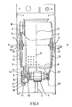
- FIG. 1 is a partially exploded view, partially in section, of an example of a washing and spinning machine in accordance with the invention, in which the tank 1 intended to receive the washing or rinsing water is supported by two legs with spring and shock absorber 2, with respect to an external bodywork 3 and its base.
- the tank 1 contains a washing drum 4, made of stainless steel sheet, perforated and mounted by its shafts 5 in two sealed bearings housed in the wall of the tank, the shafts 5 defining for the drum an axis of rotation AA substantially horizontal.
- the tank is open at its top and the shell 6 (or cylindrical surface) of the drum has a door for loading and unloading the washing-machine.
- the electric motor 7 for driving the drum, the shaft 8 of which penetrates directly into a housing belonging to the tank, through a seal 9.
- the drive shaft 8 carries a drive pulley 10 receiving a belt 11, toothed in the example drawn. This belt. 11 is also stretched over the ferrule 6 of the washing drum itself serving as a receiving pulley.
- the turbine 12 of a pump 13 whose body communicates with the tank through an annular space crossed by the shaft 8 between the pulley and the turbine, the pump body communicates with the piping d water drain from the washing machine.
- the washing block of the machine consisting of the tank 1, the drum 4 and the motor 7 ... is not ballasted with any inertia or balancing mass, the motor being positioned so that its mass appreciably balances the asymmetries of the tank. That is to say, the center of gravity G of the washer block remains approximately in the vertical "plane of symmetry" P perpendicular to the axis of the drum.
- plane of symmetry is meant a median plane substantially equidistant from the flanges of the tank 1 and therefore from the flanges of the drum 4, the drum occupying here all the space available inside the tank. Therefore, when filling the tank with water, and when the drum is uniformly loaded with laundry, the center of gravity of the assembly moves vertically and the tank does not tilt relative to the body.
- the tank 1, as well as the housing receiving the shaft 8, can be made of injected synthetic material, for example of lightened polypropylene or loaded with fibers.
- This solution makes it very easy to obtain in one piece the various elements of the tank, which can be made up as shown in FIGS. 1 and 2 of a substantially cylindrical main body 14, closed by a cover 15.
- the body and the cover are connected by elastic clips 16 and compress between them a seal 17.
- the geometric axis AA common to the tank and the drum, defined by the drum shafts 5, has been shown in phantom.
- the axis AA intersects the outline of the body 3 of the machine at two virtual points 40.
- the geometry of the machine according to the invention is such that the vertical walls , or flanges, of the cylindrical tank 1 are each inscribed in a cone C of axis AA, of apex one of the points 40 and of angle at the apex close to 160 °.
- the tank flanges are themselves conical, of concavity turned inwards, so that the maximum length of the tank is measured between the housings 41 formed in the center of the flanges to receive the bearings of drum shafts, and more precisely between the outer faces 42 of these housings 41.
- this maximum length of tank is equal to 90% of the width of the body between the points 40, ie for example 36/40 cm.
- the body width referred to is the interior width, but the body of this type of suspended tank machine is made of a thin sheet of steel, at most 1 mm thick, which is small compared to to the width of the tank (40 cm).
- Such a geometry makes it possible to increase the volume of the tank, therefore of the drum 4, inside a bodywork of dimensions data.
- the tension of the belt must be adjusted to a sufficient value: the force exerted between the two pulley axes will be for example 10 daN.
- the adjustment of this belt tension is obtained by adjusting the position of a drum shaft bearing, or of the two bearings.
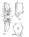
- FIG. 4 shows an exemplary embodiment of a bearing adjustable in position.
- Reference 1 here also designates the wall of the tank or an element attached to this wall to support the drum.
- the washing drum 4 carries in the center of its flange a reinforcement piece 109, on which is taken the shaft 5 of axis AA.
- a cylindrical revolving housing 111 of axis BB parallel but distinct from the axis AA of the drum 4.
- the shaft 5 is rotatably mounted in a bearing 112 which can be a smooth bearing or a ball or roller bearing. This bearing 112 is inserted into a support 113, of cylindrical shape of revolution, fitting with friction in the housing 111, and therefore also of axis BB.
- the axial immobilization of the bearing support is obtained in the example drawn as follows. From left to right, that is to say towards the inside of the tank, the support 113 rests by a flange 114 against a shoulder 115 of the housing 111. From right to left, that is to say towards the outside the tank, the support is held by the engagement of lugs 116 against a collar 117 restricting the opening of the housing 111 towards the interior of the tank.
- This collar 117 is interrupted by notches (not drawn) allowing the introduction of the lugs 116 of the support, before their locking obtained by rotation of the support, in the manner of a bayonet coupling.
- the number of pins 116 will for example be four, as suggested in FIG. 5b.
- the seal between the inside and the outside of the washing machine tank is ensured by two seals.
- an O-ring 118 made of elastic material, is compressed inside a peripheral groove hollowed out in the cylindrical surface of the support.
- a lip seal 119 is threaded onto the shaft and its lip presses against a seal surface 120 belonging to the support.
- the seal surface can consist of a stainless steel washer around which the bearing support is molded.
- the seal 119 is positioned on the drum shaft by a shoulder 121 of this shaft.
- FIG. 5a is a half-view, from the outside, of the assembly of the shaft 5 shown in FIG. 4.
- axis AA eccentricity of the shaft 5 and of its bearing 112
- axis BB bearing support 113
- the rotation of the support 113 relative to its housing in the tank wall 1 is braked by the action of a radial pawl 122 belonging to the support 113 against an internal peripheral toothing 123 of the flare of the housing corresponding to the shoulder 115.
- Ratchet and teeth can be doubled symmetrically with respect to the axis BB.
- This toothing 123 has the shape of that of a ratchet wheel, allowing rotation of the support 113 only in the direction of the arrow F.
- This rotation is moreover limited by a stud 124. belonging to the wall of the tank, and more particularly projecting from the surface of the shoulder 115.
- the flange 114 of the support has a notch delimited by two heels 126 and 127 defining the maximum stroke in rotation of the support.
- FIG. 5b is a half view of the interior of the same fraction of the bearing support 113 shown isolated from the tank and the drum shaft.
- the bearing support 113 and the tank wall 1, at least in its part surrounding the housing 111, are advantageously made of injection-molded synthetic material. This allows parts with complex contours to be obtained in one piece, in particular the housing 111, its shoulder 115, its stud 124, its teeth 123 and its collar 117 with the notches corresponding to the lugs 116 of the support, and the bearing support. 113 with its flange 114, the heels 126 and 127, the pawl 122, the lugs 116, and including the joint surface 120, etc.
- the assembly of the elements described above is carried out as follows.
- the bearing support is introduced into its housing, the lugs 116 penetrating into their notches and the heel 127 being close to the stud 124, the support is then turned in the direction of the arrow F (FIG. 5a) for locking the lugs 116.
- This locking corresponds to the grip of the pawl 122 in the first tooth of the toothing 123.
- the support 113 is turned further until the belt tension is obtained wanted.
- the maximum rotation of the support is approximately 110 °, which, for a center distance AA-BB of 4 mm, allows a spacing of 6.5 mm from the axis AA with respect to the drive pulley of the belt.
- Figure 6 is a section through another version of the assembly described above.
- the bearing support 213 and its housing 211 are substantially identical to those of FIGS. 4, 5a, 5b, except that the resistance to rotation of the support is produced by longitudinal studs 230 projecting inside the flange 214 of the support and cooperating with notches 231 hollowed out in the shoulder 215 of the housing.
- FIG. 7 represents in section the various organs through the shaft 8 of the motor 7 in the zone where it enters the tank 1.
- the wall of the tank has a face 21 substantially normal to the axis of the drum ( therefore of the motor) and which constitutes the wall of the housing situated under the tank and containing the driving pulley 10 and the pump impeller (see also Figures 2 and 3).
- This face 21 is pierced with an opening 22 around which is mounted the static seal 19 which has the shape of a ring of elastic material.
- An outer peripheral groove forms on the seal 19 two wings 23, 24 which match, inside and outside the tank, the edges of the opening 22.
- the edges of the opening 22 and the wings 23, 24 of the seal may have peripheral grooves and corresponding projecting parts, as illustrated in FIG. 2.
- the static seal 19 has at its center a cylindrical recess intended to receive a projecting part 70 of the front flange 71 of the motor 7.
- the region of the motor supporting the bearing 72 through which the motor shaft exits is called the front flange 71 of the motor.
- the assembly being here covered with a cap 74 of waterproof and electrically insulating synthetic material in order to protect the front flange 71, here metallic, from any contact with the water of the tank .
- the seal between the static seal 19 and the front flange 71 of the motor or, here, the cover 74 which covers it, is preferably ensured at the location of the cylindrical recess of the seal, by a peripheral lip 25 bearing elastically against the projecting part 70 of the front flange 71 (or of the cap 74).
- this seal is produced in the absence of longitudinal pressure exerted by the motor against the static seal 19 and is maintained even in the event of slight longitudinal displacements of the motor or of oscillations of the motor around its axis.
- the static seal 19 is therefore used to determine the position of the motor 7 relative to the tank 1, it attenuates the transmission of vibrations from the engine to the tank, finally it provides sealing between the tank wall and the fixed external structure. of the motor.
- a rotary joint 9 consisting of an elastic ring secured to the shaft 8 and one lip of which presses elastically against a face perpendicular to the axis belonging to the cap 74 covering the front flange of the engine.
- a sleeve 81 of impermeable and insulating material covers it with its free end in the vicinity of the bearing 72.
- the sleeve 81 is fixed to the shaft 8. It is on this sleeve 81 that are shaped the shoulder retaining the rotary joint 9 and the drive pulley 10.
- the sleeve 81 is extended by an axis intended to receive the pump turbine 12 (fig. 1). It can be seen that the seal around the rotating shaft is not dependent on the relative position of the motor and the tank wall.
- the seal 20 is located between the shaft 8 and the front flange of the motor, or more exactly between the insulating parts which cover these two elements. This arrangement avoids having to position the motor very precisely on the tank, and therefore allows a certain elasticity of its fixing.
- FIG. 8 is an illustration of means which make it possible to fix the motor to the tank so that its front flange occupies the position shown in FIG. 7. For simplicity, the elements are shown separate therefrom.
- the flange 75 supporting the rear bearing of its shaft 8 has a portion 76 projecting axially.
- This projecting part 76 can be enclosed in a collar 30, a ring of elastic material 31 being interposed between the collar 30 and the "projecting part 76 of the motor.
- the collar 30 is carried by a structure 32 with which it is integral, the whole being molded in polypropylene for example, itself fixed to the tank 1 of the washing machine (fig. 1).
- This fixing is obtained by two sliders 33 in T, belonging to the structure 32 collar holder, capable of s 'engage in two slides 34, of corresponding profile, arranged in frames 35 belonging to the tank (see figures' 2 and 3).
- the tank 1 is made of injected synthetic material
- frames 35 and slides 34 are obtained during
- the slides 34 and the slides 33 are parallel to the motor shaft, which makes it possible in particular to adapt this attachment to motors of various lengths.
- the immobilization of the slides in their slide is obtained by any suitable means, eg example by means of teeth forming pawls.
- the projecting part 76 of the rear flange of the motor, as well as the collar 30 and the elastic ring 31 are of polygonal section so as to allow only slight oscillations of the motor around its axis.
Applications Claiming Priority (8)
| Application Number | Priority Date | Filing Date | Title |
|---|---|---|---|
| FR7923321 | 1979-09-19 | ||
| FR7923322A FR2465825A1 (fr) | 1979-09-19 | 1979-09-19 | Machine a laver a palier de tambour reglable |
| FR7923321A FR2465826A1 (fr) | 1979-09-19 | 1979-09-19 | Machine a laver et a essorer le linge a entrainement du tambour par courroie |
| FR7923322 | 1979-09-19 | ||
| FR8018210 | 1980-08-20 | ||
| FR8018210A FR2488922A1 (fr) | 1980-08-20 | 1980-08-20 | Machine a laver et a essorer le linge a entrainement du tambour par courroie immergee |
| FR8018209 | 1980-08-20 | ||
| FR8018209A FR2488921A1 (fr) | 1980-08-20 | 1980-08-20 | Machine a laver et a essorer le linge a entrainement du tambour par courroie immergee |
Publications (2)
| Publication Number | Publication Date |
|---|---|
| EP0026018A1 true EP0026018A1 (de) | 1981-04-01 |
| EP0026018B1 EP0026018B1 (de) | 1984-05-30 |
Family
ID=27446408
Family Applications (1)
| Application Number | Title | Priority Date | Filing Date |
|---|---|---|---|
| EP80200866A Expired EP0026018B1 (de) | 1979-09-19 | 1980-09-15 | Maschine zum Waschen und Schleudern von Wäsche, deren Trommel mittels eines untergetauchten Riemens angetrieben wird |
Country Status (3)
| Country | Link |
|---|---|
| EP (1) | EP0026018B1 (de) |
| DE (2) | DE3068041D1 (de) |
| ES (1) | ES495114A0 (de) |
Cited By (17)
| Publication number | Priority date | Publication date | Assignee | Title |
|---|---|---|---|---|
| FR2506353A1 (fr) * | 1981-05-19 | 1982-11-26 | Philips Nv | Suspension reglable pour le moteur d'entrainement du tambour dans des machines a laver notamment des machines a laver a usage domestique |
| FR2586434A1 (fr) * | 1985-08-20 | 1987-02-27 | Esswein Sa | Panier a linge a axes incorpores, et lave-linge muni d'un tel panier |
| FR2605652A1 (fr) * | 1986-10-28 | 1988-04-29 | Ciapem | Lave-linge a pompes de recyclage et de vidange |
| FR2606798A1 (fr) * | 1986-11-18 | 1988-05-20 | Ciapem | Lave-linge muni d'une cuve en matiere synthetique |
| EP0326801A1 (de) * | 1988-02-01 | 1989-08-09 | Bosch Siemens Hausgeraete | Waschmaschine mit einem Laugenbehälter. |
| TR26623A (tr) * | 1988-10-05 | 1994-05-04 | SELüLOZIK ELYAFIN TRIFENDIOKSAZINLI REAKTIF BOYAR MADDELERLE TEK SAFHALI BASKISINA MAHSUS USUL | |
| WO1995017543A1 (en) * | 1993-12-23 | 1995-06-29 | Electrolux Zanussi Elettrodomestici S.P.A. | Improvement in the washing tub of a clothes washing machine |
| FR2759713A1 (fr) * | 1997-02-14 | 1998-08-21 | Bosch Siemens Hausgeraete | Agencement de palier avec dispositif d'etancheite pour le tambour d'une machine a laver de menage |
| ES2151330A1 (es) * | 1997-01-21 | 2000-12-16 | Balay Sa | Sistema de cierre mejorado para cuba plastica de lavadora. |
| GB2360296A (en) * | 2000-03-15 | 2001-09-19 | Monotub Ind Plc | Washing machine drive |
| WO2004059069A1 (en) * | 2002-12-27 | 2004-07-15 | Arcelik Anonim Sirketi (A.S.) | Washing/drying machine |
| EP2436826A1 (de) * | 2010-09-30 | 2012-04-04 | Whirlpool Corporation | Waschmaschine mit einem kompakten Trommelantriebssystem |
| EP2631343A1 (de) | 2012-02-27 | 2013-08-28 | Electrolux Home Products Corporation N.V. | Waschwanneneinheit und Waschmaschine |
| EP2631345A1 (de) | 2012-02-27 | 2013-08-28 | Electrolux Home Products Corporation N.V. | Waschwanneneinheit und Waschmaschine |
| CN104180790A (zh) * | 2014-09-03 | 2014-12-03 | 重庆航伟光电科技有限公司 | 一种新型Si-APD器件 |
| WO2018127314A1 (en) * | 2016-12-08 | 2018-07-12 | Arcelik Anonim Sirketi | A washing machine wherein the electric motor is integrated to the tub |
| CN112663288A (zh) * | 2020-12-15 | 2021-04-16 | 珠海格力电器股份有限公司 | 一种洗衣机 |
Families Citing this family (5)
| Publication number | Priority date | Publication date | Assignee | Title |
|---|---|---|---|---|
| KR100565652B1 (ko) * | 2003-12-30 | 2006-03-30 | 엘지전자 주식회사 | 톱로딩 방식 드럼세탁기의 구동부 |
| DE102012105575B4 (de) | 2012-06-26 | 2022-10-20 | Adient Us Llc | Lagerungseinheit |
| CN105040361A (zh) * | 2015-06-30 | 2015-11-11 | 温州经济技术开发区滨海志杰机电产品设计工作室 | 锰合金盘式马达卡箍弹簧消振漂洗设备 |
| CN105040360A (zh) * | 2015-06-30 | 2015-11-11 | 张筱秋 | 铬合金鼠笼式电机法兰活塞减震滚洗器 |
| FR3087507B1 (fr) * | 2018-10-23 | 2021-01-08 | Renault Sas | Dispositif de realignement vertical |
-
1980
- 1980-09-15 EP EP80200866A patent/EP0026018B1/de not_active Expired
- 1980-09-15 DE DE8080200866T patent/DE3068041D1/de not_active Expired
- 1980-09-17 ES ES495114A patent/ES495114A0/es active Granted
- 1980-09-17 DE DE19808024841U patent/DE8024841U1/de not_active Expired
Non-Patent Citations (2)
| Title |
|---|
| Eléments de la technique relevés: néant. * |
| Néant * |
Cited By (25)
| Publication number | Priority date | Publication date | Assignee | Title |
|---|---|---|---|---|
| FR2506353A1 (fr) * | 1981-05-19 | 1982-11-26 | Philips Nv | Suspension reglable pour le moteur d'entrainement du tambour dans des machines a laver notamment des machines a laver a usage domestique |
| FR2586434A1 (fr) * | 1985-08-20 | 1987-02-27 | Esswein Sa | Panier a linge a axes incorpores, et lave-linge muni d'un tel panier |
| FR2605652A1 (fr) * | 1986-10-28 | 1988-04-29 | Ciapem | Lave-linge a pompes de recyclage et de vidange |
| EP0267837A1 (de) * | 1986-10-28 | 1988-05-18 | Ciapem | Waschmaschine mit Umlauf- und Entleerungspumpen |
| FR2606798A1 (fr) * | 1986-11-18 | 1988-05-20 | Ciapem | Lave-linge muni d'une cuve en matiere synthetique |
| EP0272949A1 (de) * | 1986-11-18 | 1988-06-29 | Ciapem | Waschmaschine mit einem Laugenbehälter aus Kunststoff |
| EP0326801A1 (de) * | 1988-02-01 | 1989-08-09 | Bosch Siemens Hausgeraete | Waschmaschine mit einem Laugenbehälter. |
| EP0326801A3 (en) * | 1988-02-01 | 1989-10-18 | Bosch-Siemens Hausgerate Gmbh | Washing machine or dish washer with a tub |
| EP0500144A1 (de) * | 1988-02-01 | 1992-08-26 | Bosch-Siemens Hausgeräte GmbH | Waschmaschine mit einem Laugenbehälter |
| TR26623A (tr) * | 1988-10-05 | 1994-05-04 | SELüLOZIK ELYAFIN TRIFENDIOKSAZINLI REAKTIF BOYAR MADDELERLE TEK SAFHALI BASKISINA MAHSUS USUL | |
| WO1995017543A1 (en) * | 1993-12-23 | 1995-06-29 | Electrolux Zanussi Elettrodomestici S.P.A. | Improvement in the washing tub of a clothes washing machine |
| US5699682A (en) * | 1993-12-23 | 1997-12-23 | Electrolux Zanussi Elettrodomestici S.P.A. | Washing tub of a clothes washing machine |
| CN1076767C (zh) * | 1993-12-23 | 2001-12-26 | 伊莱亚斯·扎纳西家用电器股份公司 | 洗衣机洗筒的改进 |
| ES2151330A1 (es) * | 1997-01-21 | 2000-12-16 | Balay Sa | Sistema de cierre mejorado para cuba plastica de lavadora. |
| FR2759713A1 (fr) * | 1997-02-14 | 1998-08-21 | Bosch Siemens Hausgeraete | Agencement de palier avec dispositif d'etancheite pour le tambour d'une machine a laver de menage |
| GB2360296A (en) * | 2000-03-15 | 2001-09-19 | Monotub Ind Plc | Washing machine drive |
| WO2004059069A1 (en) * | 2002-12-27 | 2004-07-15 | Arcelik Anonim Sirketi (A.S.) | Washing/drying machine |
| EP2436826A1 (de) * | 2010-09-30 | 2012-04-04 | Whirlpool Corporation | Waschmaschine mit einem kompakten Trommelantriebssystem |
| EP2631343A1 (de) | 2012-02-27 | 2013-08-28 | Electrolux Home Products Corporation N.V. | Waschwanneneinheit und Waschmaschine |
| EP2631345A1 (de) | 2012-02-27 | 2013-08-28 | Electrolux Home Products Corporation N.V. | Waschwanneneinheit und Waschmaschine |
| WO2013127739A2 (en) | 2012-02-27 | 2013-09-06 | Electrolux Home Products Corporation N.V. | Washing tub unit and washing machine |
| WO2013127743A2 (en) | 2012-02-27 | 2013-09-06 | Electrolux Home Products Corporation N.V. | Washing tub unit and washing machine |
| CN104180790A (zh) * | 2014-09-03 | 2014-12-03 | 重庆航伟光电科技有限公司 | 一种新型Si-APD器件 |
| WO2018127314A1 (en) * | 2016-12-08 | 2018-07-12 | Arcelik Anonim Sirketi | A washing machine wherein the electric motor is integrated to the tub |
| CN112663288A (zh) * | 2020-12-15 | 2021-04-16 | 珠海格力电器股份有限公司 | 一种洗衣机 |
Also Published As
| Publication number | Publication date |
|---|---|
| ES8105806A1 (es) | 1981-06-01 |
| DE3068041D1 (en) | 1984-07-05 |
| EP0026018B1 (de) | 1984-05-30 |
| ES495114A0 (es) | 1981-06-01 |
| DE8024841U1 (de) | 1981-03-12 |
Similar Documents
| Publication | Publication Date | Title |
|---|---|---|
| EP0026018B1 (de) | Maschine zum Waschen und Schleudern von Wäsche, deren Trommel mittels eines untergetauchten Riemens angetrieben wird | |
| EP0152359A1 (de) | Vorrichtung und Verfahren zum Waschen von Wäsche in einer Maschine mit einem flüssigen Waschmittel | |
| FR3053394B1 (fr) | Poulie de decouplage a embrayage deporte | |
| FR2560236A1 (fr) | Machine de blanchisserie | |
| EP0053960B1 (de) | Seitliche Verbindungsvorrichtung eines Scheibenwischerblattes | |
| FR2665736A1 (fr) | Appareil absorbant l'energie vibratoire. | |
| EP0611216B1 (de) | Verbesserungen an hydraulischen Schwingungsdämpfern | |
| FR2508499A1 (fr) | Broche de retordage entrainee par un moteur electrique individuel | |
| EP0551370B1 (de) | Zentrifugalmotorpumpe | |
| EP0702925A1 (de) | Antriebsscheibe und Maschine zum Behandeln von Fussböden | |
| FR2584483A1 (fr) | Appareil secheur tournant pour plaquettes de semi-conducteurs. | |
| FR2751522A1 (fr) | Disque d'entrainement pour l'outil d'une machine pour la mise en etat et/ou l'entretien des sols et machine pourvue d'un tel disque | |
| FR2460877A1 (fr) | Dispositif pour le bobinage de matieres textiles | |
| EP0773362A1 (de) | Vorrichtung für die Aufhängung einer Pumpe und/oder Sieb zur Pumpeneinheit gehörend | |
| FR2511401A1 (fr) | Machine a laver et a essorer le linge a cuve suspendue | |
| CA2976146A1 (fr) | Dispositif d'equilibrage pour une machine a tambour rotatif et machine comprenant un tambour rotatif equipe d'un tel dispositif | |
| FR2742843A1 (fr) | Dispositif de fixation axiale d'un moteur sur un bati | |
| FR2940217A1 (fr) | Dispositif d'essuie-glace, notamment pour un vehicule automobile | |
| FR2488922A1 (fr) | Machine a laver et a essorer le linge a entrainement du tambour par courroie immergee | |
| EP0604262A1 (de) | Schwingungsdämpfer eines Laugenbehälters einer Waschmaschine | |
| FR2465825A1 (fr) | Machine a laver a palier de tambour reglable | |
| FR2465826A1 (fr) | Machine a laver et a essorer le linge a entrainement du tambour par courroie | |
| FR2717232A1 (fr) | Disque d'embrayage pour un embrayage à friction dans un véhicule automobile. | |
| EP1021122B1 (de) | Einheit umfassend eine Auswringvorrichtung und ein Fussbodenwischgerät mit einem Wischgerätteil und einem Stiel | |
| EP0475867B1 (de) | Wäscher-Tür für Massagevorrichtung |
Legal Events
| Date | Code | Title | Description |
|---|---|---|---|
| PUAI | Public reference made under article 153(3) epc to a published international application that has entered the european phase |
Free format text: ORIGINAL CODE: 0009012 |
|
| AK | Designated contracting states |
Designated state(s): DE FR GB IT |
|
| 17P | Request for examination filed |
Effective date: 19810415 |
|
| RAP1 | Party data changed (applicant data changed or rights of an application transferred) |
Owner name: N.V. PHILIPS' GLOEILAMPENFABRIEKEN Owner name: CONSTRUCTIONS ELECTRO-MECANIQUES D'AMIENS |
|
| ITF | It: translation for a ep patent filed |
Owner name: ING. C. GREGORJ S.P.A. |
|
| GRAA | (expected) grant |
Free format text: ORIGINAL CODE: 0009210 |
|
| AK | Designated contracting states |
Designated state(s): DE FR GB IT |
|
| REF | Corresponds to: |
Ref document number: 3068041 Country of ref document: DE Date of ref document: 19840705 |
|
| PLBE | No opposition filed within time limit |
Free format text: ORIGINAL CODE: 0009261 |
|
| STAA | Information on the status of an ep patent application or granted ep patent |
Free format text: STATUS: NO OPPOSITION FILED WITHIN TIME LIMIT |
|
| 26N | No opposition filed | ||
| REG | Reference to a national code |
Ref country code: FR Ref legal event code: TP |
|
| REG | Reference to a national code |
Ref country code: FR Ref legal event code: TP |
|
| ITPR | It: changes in ownership of a european patent |
Owner name: CESSIONE;WHIRLPOOL INTERNATIONAL B.V. |
|
| ITTA | It: last paid annual fee | ||
| REG | Reference to a national code |
Ref country code: FR Ref legal event code: CD |
|
| PGFP | Annual fee paid to national office [announced via postgrant information from national office to epo] |
Ref country code: DE Payment date: 19951115 Year of fee payment: 16 |
|
| PGFP | Annual fee paid to national office [announced via postgrant information from national office to epo] |
Ref country code: GB Payment date: 19960906 Year of fee payment: 17 |
|
| PGFP | Annual fee paid to national office [announced via postgrant information from national office to epo] |
Ref country code: FR Payment date: 19960910 Year of fee payment: 17 |
|
| PG25 | Lapsed in a contracting state [announced via postgrant information from national office to epo] |
Ref country code: DE Effective date: 19970603 |
|
| PG25 | Lapsed in a contracting state [announced via postgrant information from national office to epo] |
Ref country code: GB Free format text: LAPSE BECAUSE OF NON-PAYMENT OF DUE FEES Effective date: 19970915 |
|
| PG25 | Lapsed in a contracting state [announced via postgrant information from national office to epo] |
Ref country code: FR Free format text: THE PATENT HAS BEEN ANNULLED BY A DECISION OF A NATIONAL AUTHORITY Effective date: 19970930 |
|
| GBPC | Gb: european patent ceased through non-payment of renewal fee |
Effective date: 19970915 |
|
| REG | Reference to a national code |
Ref country code: FR Ref legal event code: ST |