EP0267115A2 - Outil pour perforer - Google Patents
Outil pour perforer Download PDFInfo
- Publication number
- EP0267115A2 EP0267115A2 EP19870402476 EP87402476A EP0267115A2 EP 0267115 A2 EP0267115 A2 EP 0267115A2 EP 19870402476 EP19870402476 EP 19870402476 EP 87402476 A EP87402476 A EP 87402476A EP 0267115 A2 EP0267115 A2 EP 0267115A2
- Authority
- EP
- European Patent Office
- Prior art keywords
- blank
- die
- female die
- piercing
- cutting
- Prior art date
- Legal status (The legal status is an assumption and is not a legal conclusion. Google has not performed a legal analysis and makes no representation as to the accuracy of the status listed.)
- Granted
Links
Images


Classifications
-
- B—PERFORMING OPERATIONS; TRANSPORTING
- B21—MECHANICAL METAL-WORKING WITHOUT ESSENTIALLY REMOVING MATERIAL; PUNCHING METAL
- B21D—WORKING OR PROCESSING OF SHEET METAL OR METAL TUBES, RODS OR PROFILES WITHOUT ESSENTIALLY REMOVING MATERIAL; PUNCHING METAL
- B21D28/00—Shaping by press-cutting; Perforating
- B21D28/24—Perforating, i.e. punching holes
- B21D28/30—Perforating, i.e. punching holes in annular parts, e.g. rims
-
- Y—GENERAL TAGGING OF NEW TECHNOLOGICAL DEVELOPMENTS; GENERAL TAGGING OF CROSS-SECTIONAL TECHNOLOGIES SPANNING OVER SEVERAL SECTIONS OF THE IPC; TECHNICAL SUBJECTS COVERED BY FORMER USPC CROSS-REFERENCE ART COLLECTIONS [XRACs] AND DIGESTS
- Y10—TECHNICAL SUBJECTS COVERED BY FORMER USPC
- Y10T—TECHNICAL SUBJECTS COVERED BY FORMER US CLASSIFICATION
- Y10T83/00—Cutting
- Y10T83/384—By tool inside hollow work
- Y10T83/391—With means to position tool[s] for cutting
-
- Y—GENERAL TAGGING OF NEW TECHNOLOGICAL DEVELOPMENTS; GENERAL TAGGING OF CROSS-SECTIONAL TECHNOLOGIES SPANNING OVER SEVERAL SECTIONS OF THE IPC; TECHNICAL SUBJECTS COVERED BY FORMER USPC CROSS-REFERENCE ART COLLECTIONS [XRACs] AND DIGESTS
- Y10—TECHNICAL SUBJECTS COVERED BY FORMER USPC
- Y10T—TECHNICAL SUBJECTS COVERED BY FORMER US CLASSIFICATION
- Y10T83/00—Cutting
- Y10T83/384—By tool inside hollow work
- Y10T83/395—One tool having only rectilinear motion[s]
- Y10T83/398—Internal tool is an active cutter
-
- Y—GENERAL TAGGING OF NEW TECHNOLOGICAL DEVELOPMENTS; GENERAL TAGGING OF CROSS-SECTIONAL TECHNOLOGIES SPANNING OVER SEVERAL SECTIONS OF THE IPC; TECHNICAL SUBJECTS COVERED BY FORMER USPC CROSS-REFERENCE ART COLLECTIONS [XRACs] AND DIGESTS
- Y10—TECHNICAL SUBJECTS COVERED BY FORMER USPC
- Y10T—TECHNICAL SUBJECTS COVERED BY FORMER US CLASSIFICATION
- Y10T83/00—Cutting
- Y10T83/384—By tool inside hollow work
- Y10T83/403—With manually actuated means to position or facilitate positioning of work
-
- Y—GENERAL TAGGING OF NEW TECHNOLOGICAL DEVELOPMENTS; GENERAL TAGGING OF CROSS-SECTIONAL TECHNOLOGIES SPANNING OVER SEVERAL SECTIONS OF THE IPC; TECHNICAL SUBJECTS COVERED BY FORMER USPC CROSS-REFERENCE ART COLLECTIONS [XRACs] AND DIGESTS
- Y10—TECHNICAL SUBJECTS COVERED BY FORMER USPC
- Y10T—TECHNICAL SUBJECTS COVERED BY FORMER US CLASSIFICATION
- Y10T83/00—Cutting
- Y10T83/566—Interrelated tool actuating means and means to actuate work immobilizer
-
- Y—GENERAL TAGGING OF NEW TECHNOLOGICAL DEVELOPMENTS; GENERAL TAGGING OF CROSS-SECTIONAL TECHNOLOGIES SPANNING OVER SEVERAL SECTIONS OF THE IPC; TECHNICAL SUBJECTS COVERED BY FORMER USPC CROSS-REFERENCE ART COLLECTIONS [XRACs] AND DIGESTS
- Y10—TECHNICAL SUBJECTS COVERED BY FORMER USPC
- Y10T—TECHNICAL SUBJECTS COVERED BY FORMER US CLASSIFICATION
- Y10T83/00—Cutting
- Y10T83/647—With means to convey work relative to tool station
- Y10T83/6667—Work carrier rotates about axis fixed relative to tool station
-
- Y—GENERAL TAGGING OF NEW TECHNOLOGICAL DEVELOPMENTS; GENERAL TAGGING OF CROSS-SECTIONAL TECHNOLOGIES SPANNING OVER SEVERAL SECTIONS OF THE IPC; TECHNICAL SUBJECTS COVERED BY FORMER USPC CROSS-REFERENCE ART COLLECTIONS [XRACs] AND DIGESTS
- Y10—TECHNICAL SUBJECTS COVERED BY FORMER USPC
- Y10T—TECHNICAL SUBJECTS COVERED BY FORMER US CLASSIFICATION
- Y10T83/00—Cutting
- Y10T83/869—Means to drive or to guide tool
- Y10T83/8733—Tool movable to cooperate selectively with one of a plurality of mating tools
-
- Y—GENERAL TAGGING OF NEW TECHNOLOGICAL DEVELOPMENTS; GENERAL TAGGING OF CROSS-SECTIONAL TECHNOLOGIES SPANNING OVER SEVERAL SECTIONS OF THE IPC; TECHNICAL SUBJECTS COVERED BY FORMER USPC CROSS-REFERENCE ART COLLECTIONS [XRACs] AND DIGESTS
- Y10—TECHNICAL SUBJECTS COVERED BY FORMER USPC
- Y10T—TECHNICAL SUBJECTS COVERED BY FORMER US CLASSIFICATION
- Y10T83/00—Cutting
- Y10T83/869—Means to drive or to guide tool
- Y10T83/8776—Constantly urged tool or tool support [e.g., spring biased]
- Y10T83/8785—Through return [noncutting] stroke
-
- Y—GENERAL TAGGING OF NEW TECHNOLOGICAL DEVELOPMENTS; GENERAL TAGGING OF CROSS-SECTIONAL TECHNOLOGIES SPANNING OVER SEVERAL SECTIONS OF THE IPC; TECHNICAL SUBJECTS COVERED BY FORMER USPC CROSS-REFERENCE ART COLLECTIONS [XRACs] AND DIGESTS
- Y10—TECHNICAL SUBJECTS COVERED BY FORMER USPC
- Y10T—TECHNICAL SUBJECTS COVERED BY FORMER US CLASSIFICATION
- Y10T83/00—Cutting
- Y10T83/869—Means to drive or to guide tool
- Y10T83/8821—With simple rectilinear reciprocating motion only
- Y10T83/8841—Tool driver movable relative to tool support
- Y10T83/8853—Including details of guide for tool or tool support
-
- Y—GENERAL TAGGING OF NEW TECHNOLOGICAL DEVELOPMENTS; GENERAL TAGGING OF CROSS-SECTIONAL TECHNOLOGIES SPANNING OVER SEVERAL SECTIONS OF THE IPC; TECHNICAL SUBJECTS COVERED BY FORMER USPC CROSS-REFERENCE ART COLLECTIONS [XRACs] AND DIGESTS
- Y10—TECHNICAL SUBJECTS COVERED BY FORMER USPC
- Y10T—TECHNICAL SUBJECTS COVERED BY FORMER US CLASSIFICATION
- Y10T83/00—Cutting
- Y10T83/929—Tool or tool with support
- Y10T83/9411—Cutting couple type
- Y10T83/9423—Punching tool
- Y10T83/9437—Shear-type female tool
Definitions
- the instant invention provides an improved piercing die for piercing a hole in a blank having an open interior and an outer wall defining a closed figure.
- the hole is cut from the interior of the blank out through the outer wall to the inside of the blank.
- the piercing die includes a base adapted for mounting on a bed of a power press.
- a slide is movably mounted on the base.
- a guide is mounted on the base and is movably connected to the slide to control movement of the slide to a straight line movement.
- a female die having a blank receptacle for holding a blank is mounted on the base.
- the female die has a cutting aperture formed therein intersecting the blank receptacle.
- a male die mateable with the cutting aperture is mounted on the, slide.
- the male die is positioned within the blank receptacle.
- the male die is movable toward the blank to cut a hole in the blank from the interior of the blank toward the outer wall to the outside of the blank.
- a cam is adapted for connection to a ram of the power press for moving with the ram.
- the ram is connectable to the slide for moving the male die toward the cutting aperture of the female die to engage the blank for cutting the hole in the blank from the interior of the blank to the outside wall.
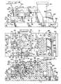
- a piercing die embodying the instant invention, is generally indicated by numeral 10.
- Piercing die 10 is mounted in a conventional power press 12.
- the piercing die generally includes a substantially flat base 14 adapted for conventional mounting on a bed 16 of press 12.
- a slide 18 is slideably mounted on base 14 and is restricted to a straight line movement by a fixed guide 20.
- a female die 22 is rotatably supported on guide 20.
- a male die 24 is connected to slide 18 and is positioned inside of the female die. The male die is cooperative with female die 22 for piercing a hole through a workpiece blank 26.
- a head 28 is connected to a conventional ram 30 of press 12.
- a sliding guide 32 is slideably mounted in head 28 for limiting movement of the male die in cooperation with the slide and guide 20.
- Slide 18 is connectable to a cam 34 mounted on ram 30 for moving the slide in one direction for piercing a hole in blank 26.
- Guide 20 has a generally rectangular body 36 with a slot 38 contained therein receiving slide 18.
- the guide includes a circular die recess 40 for receiving female die 22.
- An aperture 42 is formed in the guide to provide communication between slot 38 and the die recess 40.
- the guide is secured to base 14 by four identical pins 44.
- Slide 18 includes a foot 46 mounted on base 14. The foot is slideable within slot 38 of the guide.
- the foot has a heel 48 formed integral therewith which heel has a cam surface 50 on one side engageable with cam 34.
- a slide return 52 is connected to slide 18.
- the slide return includes a slide return bar 54 which is mounted in a slide return bar groove 56.
- the slide return bar groove 56 is formed in base 14 and is generally perpendicular to the direction of travel of slide 18.
- a pair of screws 58 hold bar 54 in groove 56.
- a pair of spring pins 60 is slideably mounted in openings 62 in stop bar 48. The pins are threadedly mounted in the end of foot 46 of slide 18.
- a spring 64 is mounted on each of the spring pins 60. The springs 64 are positioned between stop bar 54 and the end of foot 46 so that the springs constantly urge the slide away from the stop bar and toward cam 34.
- Female die 22 is rotatably mounted in circular die recess 40.
- the female die includes a blank receptacle 66 which is formed in the center of the female die.
- the wall of the female die forming the wall of the blank receptacle is a portion of a sphere having its center at the center of the female die.
- the blank receptacle includes a lower annular ledge 68 for supporting the blank.
- An upper annular lip 69 holds the blank against rising during working of the blank.
- Six die apertures 70, 72, 74, 76, 78 and 80 are formed in the female die extending radially from the blank receptacle to the outer wall of the female die. Each of the die apertures has a circular cross section and is mateable with the male die.
- the die apertures are equiangularly positioned relative to each other about a center which is at the center of the blank receptacle.
- the female die is split into a lower plate 82 and an upper plate 84.
- the split of the female die into the two plates occurs on a plane which is substantially parallel to the base and extends through the center of each of the die apertures.
- the lower plate has formed on its outer periphery six position indentations 86, 88, 90, 92, 94 and 96 which are equiangularly spaced from each other. These position indentations are cooperative with a die position assembly 98 for positioning each of the die apertures with the male die as will be described hereinafter.
- the lower plate also includes an annular die groove 100 for positioning the upper plate relative to the lower plate.
- a pair of die pins 102 and 104 also position the die plates relative to each other in that die pins 102 and 104 prevent the plates from rotating relative to each other, thereby maintaining the plates in alignment to keep the die apertures as circular apertures.
- Upper plate 84 includes an integral die ring 106 which is mateably positioned in annular die groove 100. The mating of the die ring with the annular die groove holds the plates in firm position in cooperation with the die pins which prevent rotation of the upper and lower plates relative to each other.
- Die position assembly 98 positions the die apertures relative to the male die.
- the die position assembly includes a spring aperture 108 in body 36 of guide 20.
- a ball 110 is positioned in the spring aperture and is engageable with the lower plate at the position indentations for releasably holding the female die against rotation in the recess.
- a position spring 112 is mounted in the aperture in engagement with ball 110 to urge the ball toward the female die.
- a cap 114 is fixed to the guide body to hold the spring in position.
- the indentations are positioned relative to the die apertures so that as the female die is rotated, the ball drops into a position indentation to hold the female die in a position with a selected die aperture aligned with the male die.
- Male die 24 which has a circular cross section and is mateable with the die apertures is mounted on a male die support 116.
- the male die support is fixed to foot 46 of slide 18.
- Foot 46 has a transverse groove 118 with a circular recess 120 in the groove formed in the upper surface of the foot.
- the male die support includes a post 122 which has a pair of opposed flat faces 124 and 126.
- Male die 24 is fixed to face 124 at the midportion of the post.
- the flat faces have their lower portions positioned in groove 118.
- Post 122 includes a boss 128 formed in its bottom, which boss is mateably positioned in recess 120.
- Post 122 has a pair of parallel sides 130.
- a conventional machine screw 132 is fixed in foot 46 to fix post 122 to foot 46.
- a guide stud 134 is formed integral with the top of the post.
- the guide stud has a domed upper portion 136 to facilitate connection with the sliding guides.
- a guide pillar 138 is mounted in heel 48. Heel 48 has a pillar aperture 140 which receives the guide pillar. A conventional screw 142 secures the guide pillar in aperture 140.
- the guide pillar has a domed pillar head 144 similar to the domed head 136 of guide stud 134. The guide stud and the guide pillar are aligned with each other and with slot 38 of guide 20 to guide slide 18 in a straight line.
- Head 28 includes a head body 146 which has four head pins 148 threadedly connected thereto.
- the head pins are slideably mounted in ram 30 and are held in the ram by their respective heads 149.
- a pair of coil springs 150 is positioned in respective spring sockets 151 in ram 30 and in engagement with head body 146 constantly urging the head body away from ram 30. However, the movement of the head away from the ram is limited by the head pins.
- a guide groove 152 is formed in the underside of the head body.
- a pair of guide supports 154 and 156 is secured to the head body and partially overlap the guide groove.
- Sliding guide 32 is slideably mounted in guide groove 152.
- Sliding guide 32 includes an elongated guide runner 160 which has a generally T-shaped cross section.
- the T-shaped cross section allows the sliding guide to fit in the guide groove 152 and have guide supports 154 and 156 hold the sliding guide within the head.
- the sliding guide includes a forward opening 162 adapted to receive guide stud 134 and a rear slot 164 adapted to receive guide pillar 138.
- a guide return assembly 166 is connected to sliding guide 32.
- the guide return assembly includes a pair of guide pins 168 which are threadedly mounted in one end of guide runner 160.
- a guide return spring 170 is mounted on each of the guide pins and each spring is positioned between the end of guide runner 160 and a portion of head 128 to urge the sliding guide toward the cam.
- Cam 34 is fixed to ram 30 and moves vertically with the ram.
- Cam 34 includes a cam face 172 which is engageable with cam surface 50 of heel 48.
- Cam face 172 is also engageable with a surface 174 of guide runner 160.
- the cam also has a back face 176 which is adapted for holding the cam in a horizontal direction.
- a slide stop 178 is secured to base 14 by a pair of conventional machine screws 180.
- a cam wall 182 is secured to base 14 by a pair of machine screws 184.
- the cam wall includes a cam wall surface 186 which is engageable with back face wall 176 of the cam.
- a cam wall stop 188 is mounted in a cam wall stop groove 190 in base 14. The cam wall stop is held in position by a pair of conventional screws 192 to secure the cam wall against movement relative to the base.
- the workpiece or blank 26 is, in this instance, made of cold rolled steel.
- the blank is a continuous closed figure having a hollow center.
- the blank has its outer surface formed as a portion of a sphere and the inner surface is also a portion of a sphere.
- the blank receptacle 66 of the female die conforms to the outer surface of the blank. As was mentioned above, the female die is split on a plane extending through the center of the die apertures.
- the blank is inserted into the blank receptacle by first lifting upper plate 84 off of lower plate 82 and positioning the blank in the blank receptacle with the male die and male die support within the open interior of the blank. The upper plate 84 is then placed on the lower plate to complete blank receptacle 66.
- the conventional power press 12 is operated as is conventional. After the upper plate is placed into position, the ram is brought down toward the female die.
- the guide stud and the guide pillar mate with the forward opening and rear slot, respectively, so that the sliding guide is connected to the guide stud and guide pillar for guiding the male die in a straight line which is on the same straight line as that along which the slot 38 in body 36 guides the male die through the cooperation of body 36 with slide 18.
- Ram 30 in conventional operation moves down until head 28 engages the upper surface of upper plate 84 of the female die.
- the engagement of the head with the female die secures the female die into position and holds the upper plate in tight engagement with the lower plate.
- cam 34 moves downward so that cam surface 172 engages the surface 174 of sliding guide 158 and cam surface 50 of the slide while back face 176 engages cam wall surface 186.
- Continued movement of cam 34 downward moves the slide toward the left as viewed in figures 6 and 7.
- the movement of the slide is against the force of springs 64 and moves the male die toward the blank.
- the male die engages the blank and forces the metal of the blank out through die aperture 80.
- Movement of the cam is restricted to a vertical movement since the cam wall 182 prevents the cam from moving to the right as viewed in figures 6 and 7.
- a slug which is the metal cut out of the blank, is forced out through the die aperture.
- the movement of the slide is restricted to a straight line movement by slot 38 in the guide body and sliding guide 158 which is in engagement with post 122 of the male die support and guide pillar 138.
- cam 34 moves upward.
- springs 64 push the die toward the right as viewed in figures 6 and 7 until the slide comes into engagement with slide stop 178.
- the sliding guide is moved toward the right by springs 170.
- the cam and the head continue their upward movement so that heads 149 come into engagement with the ram to lift head 28 with sliding guide 158 from the female die and the slide.
- the lifting of the head from the female die releases the female die so that the female die may be rotated in the circular die recess until the next die aperture is aligned with the male die and the die post assembly releasably holds the female die in the next position.
- the ram is again moved downward with the guide stud and guide pillar being positioned in the forward opening and rear slot, respectively.
- the continued downward movement of the ram has the instant piercing die go through another cycle as described above.
- the blank is rotated at the end of each cycle so that a sufficient number of holes are punched in the blank.
- the holes are punched through the blank from the interior of the blank to the outside, thereby giving a particularly desired result wherein the interior surface of the blank has the male die first engaging the interior surface rather than the exterior surface.
- the metal is cut from the blank by being pushed out from the inside out.
Applications Claiming Priority (2)
| Application Number | Priority Date | Filing Date | Title |
|---|---|---|---|
| US06/926,953 US4802393A (en) | 1986-11-04 | 1986-11-04 | Piercing die |
| US926953 | 1986-11-04 |
Publications (3)
| Publication Number | Publication Date |
|---|---|
| EP0267115A2 true EP0267115A2 (fr) | 1988-05-11 |
| EP0267115A3 EP0267115A3 (en) | 1988-09-07 |
| EP0267115B1 EP0267115B1 (fr) | 1991-10-23 |
Family
ID=25453946
Family Applications (1)
| Application Number | Title | Priority Date | Filing Date |
|---|---|---|---|
| EP19870402476 Expired - Lifetime EP0267115B1 (fr) | 1986-11-04 | 1987-11-03 | Outil pour perforer |
Country Status (5)
| Country | Link |
|---|---|
| US (1) | US4802393A (fr) |
| EP (1) | EP0267115B1 (fr) |
| JP (1) | JPS63165025A (fr) |
| CA (1) | CA1295234C (fr) |
| DE (1) | DE3774073D1 (fr) |
Families Citing this family (8)
| Publication number | Priority date | Publication date | Assignee | Title |
|---|---|---|---|---|
| DE19680783B3 (de) * | 1995-07-31 | 2014-08-14 | Oiles Corp. | Nocke für ein Preßwerkzeug |
| DE19625931C1 (de) * | 1996-06-28 | 1997-07-03 | Skf Gmbh | Vorrichtung zum Ausstanzen der Taschen eines Rollenkäfigs und damit hergestellter Rollenkäfig |
| US6769600B1 (en) * | 2000-06-16 | 2004-08-03 | Dayton-Phoenix Group, Inc. | Motor lamination notching apparatus and method with selectively positionable punches |
| US6578402B2 (en) * | 2001-03-28 | 2003-06-17 | Medsource Technologies, Llc | Trimming apparatus for a drawn part |
| JP3540308B2 (ja) * | 2002-05-16 | 2004-07-07 | ユミックス株式会社 | スライドカム型 |
| JP5899857B2 (ja) * | 2011-11-18 | 2016-04-06 | 日本精工株式会社 | ボールねじ用ナット製造装置 |
| DE102013226750A1 (de) * | 2013-12-19 | 2015-06-25 | Aktiebolaget Skf | Verfahren und Vorrichtung zum Herstellen eines Wälzlagerkäfigs |
| CN112974627A (zh) * | 2019-12-13 | 2021-06-18 | 青岛海尔智慧厨房电器有限公司 | 一种模具 |
Citations (11)
| Publication number | Priority date | Publication date | Assignee | Title |
|---|---|---|---|---|
| US1503551A (en) * | 1923-01-23 | 1924-08-05 | Budd G Nice | Band-punching machine |
| US2315340A (en) * | 1941-08-23 | 1943-03-30 | Midland Steel Prod Co | Punch |
| US2329020A (en) * | 1942-04-17 | 1943-09-07 | George F Wales | Punching device |
| US2419534A (en) * | 1945-05-30 | 1947-04-29 | Mouldings Inc | Demountable device for punching tubes |
| US2423791A (en) * | 1945-10-04 | 1947-07-08 | Krag Steel Products Inc | Dies and the like |
| US2758652A (en) * | 1953-12-07 | 1956-08-14 | Danly Mach Specialties Inc | Hydraulic punch and stripper |
| US2774132A (en) * | 1953-08-17 | 1956-12-18 | Federal Mogul Bower Bearings | Method of making roller bearing roller retainers |
| US2875829A (en) * | 1954-12-01 | 1959-03-03 | Bruno S Patrick | Apparatus for stamping surfaces |
| US3579767A (en) * | 1969-06-02 | 1971-05-25 | Gen Impact Extrusions Mfg Ltd | Method for forming flash holes in cartridge cases |
| DE2256180A1 (de) * | 1971-11-19 | 1973-05-24 | Citroen Sa | Auf eine presse montierbare einrichtung zum lochen |
| EP0128870A1 (fr) * | 1983-06-09 | 1984-12-19 | Hydrel AG | Dispositif pour le découpage fin des ouvertures dans une cage à billes |
Family Cites Families (17)
| Publication number | Priority date | Publication date | Assignee | Title |
|---|---|---|---|---|
| US1398320A (en) * | 1919-09-13 | 1921-11-29 | George W Dunsworth | Pipe-perforator |
| US1502097A (en) * | 1922-07-12 | 1924-07-22 | Emanuel J Grace | Rim-punching machine |
| US1581810A (en) * | 1924-07-02 | 1926-04-20 | Bliss E W Co | Machine for punching or swaging rims or the like |
| US1549462A (en) * | 1924-10-16 | 1925-08-11 | Birmingham Iron Foundry | Circular-multiple-punching machine |
| US2326536A (en) * | 1942-03-09 | 1943-08-10 | Mid West Hydro Pierce Inc | Machine for piercing tubes |
| US2630862A (en) * | 1951-09-05 | 1953-03-10 | Musser C Walton | Apparatus for perforating hollow cylindrical objects |
| US3286570A (en) * | 1962-02-23 | 1966-11-22 | Wallace Expanding Machines | Apparatus for forming metallic sheet members |
| US3374697A (en) * | 1965-10-21 | 1968-03-26 | Taylor Forge Inc | Method and apparatus for severing a tubular member |
| US3485124A (en) * | 1967-06-02 | 1969-12-23 | Kentucky Electronics Inc | Automatic machine for making convergence cup electrodes for color television tubes |
| US3473425A (en) * | 1967-11-13 | 1969-10-21 | Toledo Stamping & Mfg Co | Stamping apparatus |
| US3580122A (en) * | 1968-12-13 | 1971-05-25 | All Steel Equipment Inc | Apparatus for making knockouts in electrical boxes formed of plastic material |
| US3557649A (en) * | 1968-12-16 | 1971-01-26 | Northern Metal Products Inc | Centering and piercing process and apparatus |
| US3756108A (en) * | 1971-12-13 | 1973-09-04 | Western Electric Co | Tube cutter |
| US3782231A (en) * | 1972-07-21 | 1974-01-01 | L Jannetty | Piercing assembly |
| NL7308911A (fr) * | 1973-06-27 | 1974-12-31 | ||
| US4269094A (en) * | 1977-12-20 | 1981-05-26 | Burner Systems International, Inc. | Device for punching holes in tubing |
| DE3136514A1 (de) * | 1981-09-15 | 1983-03-24 | Trumpf GmbH & Co, 7257 Ditzingen | "matrize" |
-
1986
- 1986-11-04 US US06/926,953 patent/US4802393A/en not_active Expired - Fee Related
-
1987
- 1987-10-30 CA CA 550718 patent/CA1295234C/fr not_active Expired - Fee Related
- 1987-11-02 JP JP62275933A patent/JPS63165025A/ja active Pending
- 1987-11-03 EP EP19870402476 patent/EP0267115B1/fr not_active Expired - Lifetime
- 1987-11-03 DE DE8787402476T patent/DE3774073D1/de not_active Expired - Fee Related
Patent Citations (11)
| Publication number | Priority date | Publication date | Assignee | Title |
|---|---|---|---|---|
| US1503551A (en) * | 1923-01-23 | 1924-08-05 | Budd G Nice | Band-punching machine |
| US2315340A (en) * | 1941-08-23 | 1943-03-30 | Midland Steel Prod Co | Punch |
| US2329020A (en) * | 1942-04-17 | 1943-09-07 | George F Wales | Punching device |
| US2419534A (en) * | 1945-05-30 | 1947-04-29 | Mouldings Inc | Demountable device for punching tubes |
| US2423791A (en) * | 1945-10-04 | 1947-07-08 | Krag Steel Products Inc | Dies and the like |
| US2774132A (en) * | 1953-08-17 | 1956-12-18 | Federal Mogul Bower Bearings | Method of making roller bearing roller retainers |
| US2758652A (en) * | 1953-12-07 | 1956-08-14 | Danly Mach Specialties Inc | Hydraulic punch and stripper |
| US2875829A (en) * | 1954-12-01 | 1959-03-03 | Bruno S Patrick | Apparatus for stamping surfaces |
| US3579767A (en) * | 1969-06-02 | 1971-05-25 | Gen Impact Extrusions Mfg Ltd | Method for forming flash holes in cartridge cases |
| DE2256180A1 (de) * | 1971-11-19 | 1973-05-24 | Citroen Sa | Auf eine presse montierbare einrichtung zum lochen |
| EP0128870A1 (fr) * | 1983-06-09 | 1984-12-19 | Hydrel AG | Dispositif pour le découpage fin des ouvertures dans une cage à billes |
Also Published As
| Publication number | Publication date |
|---|---|
| EP0267115A3 (en) | 1988-09-07 |
| DE3774073D1 (de) | 1991-11-28 |
| JPS63165025A (ja) | 1988-07-08 |
| US4802393A (en) | 1989-02-07 |
| EP0267115B1 (fr) | 1991-10-23 |
| CA1295234C (fr) | 1992-02-04 |
Similar Documents
| Publication | Publication Date | Title |
|---|---|---|
| US4489584A (en) | Single stroke, draw and trim die assembly | |
| US3971275A (en) | Nestable die alignment means for punch press machines | |
| EP0267115A2 (fr) | Outil pour perforer | |
| JPH02104431A (ja) | 材料シートから容器端パネルを成形する方法および装置 | |
| JPS57142726A (en) | One stroke multiple stage forming press | |
| US3124876A (en) | Method of forming cupped articles | |
| EP0399339B1 (fr) | Porte-outil pour outil de marquage pour poinçonneuse | |
| CN105251867A (zh) | 一种后桥锁止垫圈两步冲二十四孔模具及其加工工艺 | |
| US2177027A (en) | Die for forming and knurling sheet metal can tops | |
| CN111283058A (zh) | 一种用于汽车支撑件的冲裁冲压生产线 | |
| SU728740A3 (ru) | Способ изготовлени зубчатого полюсного наконечника | |
| CN113996708B (zh) | 一种帽形零部件连续冲压模具 | |
| US4033168A (en) | Strip stock lifter | |
| US4170890A (en) | Punch and die assembly for use in the production of heat exchanger fins | |
| JP2001300651A (ja) | 筒体ワークの穴加工装置 | |
| US4088005A (en) | Combined rotary progressive die | |
| US2394346A (en) | Punch and die mechanism | |
| CN113369387A (zh) | 冰箱中梁组件生产装置、生产方法以及冰箱中梁组件 | |
| US4712473A (en) | Method and apparatus for marking and forming workpieces | |
| US2591483A (en) | Progressive tool and improved method of progressively forming articles from strip stock or the like | |
| EP3769858B1 (fr) | Matrices d'estampage et dispositifs de retenue guidés à utiliser dans ces matrices | |
| US3654795A (en) | Process for producing cup-shaped objects having axially extending lips | |
| CN110586760A (zh) | 一种边沿向内斜弯曲扣件液压复合模 | |
| CN211360302U (zh) | 管类件双工位冲孔、折弯成型模具 | |
| CN112122943B (zh) | 一种制动套加工工艺 |
Legal Events
| Date | Code | Title | Description |
|---|---|---|---|
| PUAI | Public reference made under article 153(3) epc to a published international application that has entered the european phase |
Free format text: ORIGINAL CODE: 0009012 |
|
| AK | Designated contracting states |
Kind code of ref document: A2 Designated state(s): DE FR GB IT |
|
| PUAL | Search report despatched |
Free format text: ORIGINAL CODE: 0009013 |
|
| AK | Designated contracting states |
Kind code of ref document: A3 Designated state(s): DE FR GB IT |
|
| ITCL | It: translation for ep claims filed |
Representative=s name: BREVETTI EUROPA S.R.L. |
|
| EL | Fr: translation of claims filed | ||
| 17P | Request for examination filed |
Effective date: 19890209 |
|
| 17Q | First examination report despatched |
Effective date: 19900301 |
|
| GRAA | (expected) grant |
Free format text: ORIGINAL CODE: 0009210 |
|
| ITF | It: translation for a ep patent filed |
Owner name: BREVETTI EUROPA S.R.L. |
|
| AK | Designated contracting states |
Kind code of ref document: B1 Designated state(s): DE FR GB IT |
|
| ET | Fr: translation filed | ||
| REF | Corresponds to: |
Ref document number: 3774073 Country of ref document: DE Date of ref document: 19911128 |
|
| PG25 | Lapsed in a contracting state [announced via postgrant information from national office to epo] |
Ref country code: GB Effective date: 19920123 |
|
| PGFP | Annual fee paid to national office [announced via postgrant information from national office to epo] |
Ref country code: DE Payment date: 19920130 Year of fee payment: 5 |
|
| PLBE | No opposition filed within time limit |
Free format text: ORIGINAL CODE: 0009261 |
|
| STAA | Information on the status of an ep patent application or granted ep patent |
Free format text: STATUS: NO OPPOSITION FILED WITHIN TIME LIMIT |
|
| REG | Reference to a national code |
Ref country code: GB Ref legal event code: PCNP |
|
| PG25 | Lapsed in a contracting state [announced via postgrant information from national office to epo] |
Ref country code: FR Effective date: 19920930 |
|
| 26N | No opposition filed | ||
| REG | Reference to a national code |
Ref country code: FR Ref legal event code: ST |
|
| PG25 | Lapsed in a contracting state [announced via postgrant information from national office to epo] |
Ref country code: DE Effective date: 19930803 |
|
| PG25 | Lapsed in a contracting state [announced via postgrant information from national office to epo] |
Ref country code: IT Free format text: LAPSE BECAUSE OF NON-PAYMENT OF DUE FEES;WARNING: LAPSES OF ITALIAN PATENTS WITH EFFECTIVE DATE BEFORE 2007 MAY HAVE OCCURRED AT ANY TIME BEFORE 2007. THE CORRECT EFFECTIVE DATE MAY BE DIFFERENT FROM THE ONE RECORDED. Effective date: 20051103 |
|
| PG25 | Lapsed in a contracting state [announced via postgrant information from national office to epo] |
Ref country code: FR Effective date: 19911130 |