EP0266302A1 - Agrégat de refroidissement et procédé pour refroidir des matières à laminer à chaud avec/sans patentage directe à pression hydraulique - Google Patents
Agrégat de refroidissement et procédé pour refroidir des matières à laminer à chaud avec/sans patentage directe à pression hydraulique Download PDFInfo
- Publication number
- EP0266302A1 EP0266302A1 EP87710010A EP87710010A EP0266302A1 EP 0266302 A1 EP0266302 A1 EP 0266302A1 EP 87710010 A EP87710010 A EP 87710010A EP 87710010 A EP87710010 A EP 87710010A EP 0266302 A1 EP0266302 A1 EP 0266302A1
- Authority
- EP
- European Patent Office
- Prior art keywords
- cooling
- cooling unit
- rolling stock
- pressurized water
- pressure chamber
- Prior art date
- Legal status (The legal status is an assumption and is not a legal conclusion. Google has not performed a legal analysis and makes no representation as to the accuracy of the status listed.)
- Granted
Links
- 238000001816 cooling Methods 0.000 title claims abstract description 160
- 238000005096 rolling process Methods 0.000 title claims abstract description 86
- 238000000034 method Methods 0.000 title claims abstract description 37
- XLYOFNOQVPJJNP-UHFFFAOYSA-N water Substances O XLYOFNOQVPJJNP-UHFFFAOYSA-N 0.000 claims abstract description 121
- 238000001704 evaporation Methods 0.000 claims abstract description 26
- 230000008020 evaporation Effects 0.000 claims abstract description 26
- 239000000203 mixture Substances 0.000 claims abstract description 18
- 230000001419 dependent effect Effects 0.000 claims abstract description 5
- 238000009825 accumulation Methods 0.000 claims description 13
- 238000009833 condensation Methods 0.000 claims description 7
- 230000005494 condensation Effects 0.000 claims description 7
- 238000006386 neutralization reaction Methods 0.000 claims description 5
- 230000033228 biological regulation Effects 0.000 claims description 4
- 230000015572 biosynthetic process Effects 0.000 claims description 4
- 239000007921 spray Substances 0.000 claims description 4
- 239000000654 additive Substances 0.000 claims description 3
- 239000000284 extract Substances 0.000 claims description 3
- 238000010438 heat treatment Methods 0.000 claims description 3
- 238000003860 storage Methods 0.000 claims description 3
- 239000000126 substance Substances 0.000 claims description 2
- 238000009834 vaporization Methods 0.000 claims description 2
- 230000008016 vaporization Effects 0.000 claims description 2
- 229910000831 Steel Inorganic materials 0.000 abstract description 5
- 238000000605 extraction Methods 0.000 abstract description 5
- 239000010959 steel Substances 0.000 abstract description 5
- 239000002184 metal Substances 0.000 abstract description 2
- 239000000470 constituent Substances 0.000 abstract 1
- 239000000498 cooling water Substances 0.000 description 5
- 238000004519 manufacturing process Methods 0.000 description 5
- 238000012546 transfer Methods 0.000 description 4
- 238000009835 boiling Methods 0.000 description 3
- XEEYBQQBJWHFJM-UHFFFAOYSA-N Iron Chemical compound [Fe] XEEYBQQBJWHFJM-UHFFFAOYSA-N 0.000 description 2
- 238000006243 chemical reaction Methods 0.000 description 2
- 239000003795 chemical substances by application Substances 0.000 description 2
- 238000010586 diagram Methods 0.000 description 2
- 230000000694 effects Effects 0.000 description 2
- 239000003623 enhancer Substances 0.000 description 2
- 238000005259 measurement Methods 0.000 description 2
- 239000004576 sand Substances 0.000 description 2
- 241001136792 Alle Species 0.000 description 1
- 229910001294 Reinforcing steel Inorganic materials 0.000 description 1
- 238000013459 approach Methods 0.000 description 1
- 238000010924 continuous production Methods 0.000 description 1
- 230000014759 maintenance of location Effects 0.000 description 1
- 239000000463 material Substances 0.000 description 1
- 238000005065 mining Methods 0.000 description 1
- 230000002787 reinforcement Effects 0.000 description 1
- 238000009331 sowing Methods 0.000 description 1
- 238000012549 training Methods 0.000 description 1
- 230000035899 viability Effects 0.000 description 1
- 238000004804 winding Methods 0.000 description 1
Images


Classifications
-
- B—PERFORMING OPERATIONS; TRANSPORTING
- B21—MECHANICAL METAL-WORKING WITHOUT ESSENTIALLY REMOVING MATERIAL; PUNCHING METAL
- B21B—ROLLING OF METAL
- B21B45/00—Devices for surface or other treatment of work, specially combined with or arranged in, or specially adapted for use in connection with, metal-rolling mills
- B21B45/02—Devices for surface or other treatment of work, specially combined with or arranged in, or specially adapted for use in connection with, metal-rolling mills for lubricating, cooling, or cleaning
- B21B45/0203—Cooling
- B21B45/0209—Cooling devices, e.g. using gaseous coolants
- B21B45/0215—Cooling devices, e.g. using gaseous coolants using liquid coolants, e.g. for sections, for tubes
- B21B45/0218—Cooling devices, e.g. using gaseous coolants using liquid coolants, e.g. for sections, for tubes for strips, sheets, or plates
-
- B—PERFORMING OPERATIONS; TRANSPORTING
- B21—MECHANICAL METAL-WORKING WITHOUT ESSENTIALLY REMOVING MATERIAL; PUNCHING METAL
- B21B—ROLLING OF METAL
- B21B45/00—Devices for surface or other treatment of work, specially combined with or arranged in, or specially adapted for use in connection with, metal-rolling mills
- B21B45/02—Devices for surface or other treatment of work, specially combined with or arranged in, or specially adapted for use in connection with, metal-rolling mills for lubricating, cooling, or cleaning
- B21B45/0203—Cooling
- B21B45/0209—Cooling devices, e.g. using gaseous coolants
- B21B45/0215—Cooling devices, e.g. using gaseous coolants using liquid coolants, e.g. for sections, for tubes
- B21B45/0224—Cooling devices, e.g. using gaseous coolants using liquid coolants, e.g. for sections, for tubes for wire, rods, rounds, bars
-
- B—PERFORMING OPERATIONS; TRANSPORTING
- B21—MECHANICAL METAL-WORKING WITHOUT ESSENTIALLY REMOVING MATERIAL; PUNCHING METAL
- B21B—ROLLING OF METAL
- B21B1/00—Metal-rolling methods or mills for making semi-finished products of solid or profiled cross-section; Sequence of operations in milling trains; Layout of rolling-mill plant, e.g. grouping of stands; Succession of passes or of sectional pass alternations
- B21B1/16—Metal-rolling methods or mills for making semi-finished products of solid or profiled cross-section; Sequence of operations in milling trains; Layout of rolling-mill plant, e.g. grouping of stands; Succession of passes or of sectional pass alternations for rolling wire rods, bars, merchant bars, rounds wire or material of like small cross-section
- B21B1/18—Metal-rolling methods or mills for making semi-finished products of solid or profiled cross-section; Sequence of operations in milling trains; Layout of rolling-mill plant, e.g. grouping of stands; Succession of passes or of sectional pass alternations for rolling wire rods, bars, merchant bars, rounds wire or material of like small cross-section in a continuous process
-
- B—PERFORMING OPERATIONS; TRANSPORTING
- B21—MECHANICAL METAL-WORKING WITHOUT ESSENTIALLY REMOVING MATERIAL; PUNCHING METAL
- B21B—ROLLING OF METAL
- B21B1/00—Metal-rolling methods or mills for making semi-finished products of solid or profiled cross-section; Sequence of operations in milling trains; Layout of rolling-mill plant, e.g. grouping of stands; Succession of passes or of sectional pass alternations
- B21B1/22—Metal-rolling methods or mills for making semi-finished products of solid or profiled cross-section; Sequence of operations in milling trains; Layout of rolling-mill plant, e.g. grouping of stands; Succession of passes or of sectional pass alternations for rolling plates, strips, bands or sheets of indefinite length
- B21B1/24—Metal-rolling methods or mills for making semi-finished products of solid or profiled cross-section; Sequence of operations in milling trains; Layout of rolling-mill plant, e.g. grouping of stands; Succession of passes or of sectional pass alternations for rolling plates, strips, bands or sheets of indefinite length in a continuous or semi-continuous process
- B21B1/26—Metal-rolling methods or mills for making semi-finished products of solid or profiled cross-section; Sequence of operations in milling trains; Layout of rolling-mill plant, e.g. grouping of stands; Succession of passes or of sectional pass alternations for rolling plates, strips, bands or sheets of indefinite length in a continuous or semi-continuous process by hot-rolling, e.g. Steckel hot mill
Definitions
- the invention relates to a cooling unit and a method for cooling hot rolled rolling stock, with / without direct patenting, in which pressurized water is pressed onto the hot rolled rolling stock surface.
- a cooling unit and process are useful that on the one hand enable the desired cooling temperature to be reached with little use of the agents and on the other hand prevent undesired overcooling of the edge zone of the rolling stock, which can lead to the formation of undesirable structural components in the finished rolling stock.
- a cooling unit and method are useful which, on the one hand, enable the desired cooling temperature to be achieved with little use of the agent and, on the other hand, enable the freely selected microstructure profile in the finished rolling stock to be achieved without undesirable structural components.
- No publication is known or accessible to the invention, which describes the phenomena when the heat is extracted from shaped, hot, continuous production goods made of steel or metal, in a pressure chamber by pressurized water, in detail; Using measuring records, he describes the different processes involved in extracting the heat from a hot rolled rolling stock in pressurized water within cooling units of different lengths with only one pressure space between the accumulation edges at the ends of the cooling unit and different amounts of pressurized water.
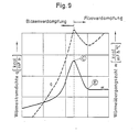
- 5 to 8 are shown for the measurement record at the cooling temperature, the measurement records of the pressure in the pressurized water line and that of the pressurized water quantities, and the symbol for the pressure chamber length.
- the numbers for the length of the pressure chamber and the amount of pressure water are ratio numbers.
- the heat withdrawal increased in seconds to full evaporation, in which the steam pressure made the pressure chamber free of pressurized water for seconds until pressurized water flowed in again just as quickly and the process was repeated at an ever higher heat transfer value level, whereby the cooling temperature has dropped in a self-propelled manner so that the finished rolled product could not have a uniform structure over the length.
- the invention is based on the object of being able to carry out the cooling of hot rolled rolling stock, from hot wide strip to wire rod, with / without direct patenting, in pressurized water in such a way that during and after the cooling thus carried out, no detectable undesirable, quality-dependent, cooling-related structural components form in the finished rolling stock can and the use of funds is comparatively low.
- the cooling unit consists primarily of the pressure chamber of the convection cooling part, the convection pressure chamber, in the hot rolled rolling stock, primarily by convection, from the pressurized water heat pressed onto the warm rolling stock surface, preferably up to the boiling point of the pressurized water, is withdrawn and secondarily from the pressure chamber of the evaporative cooling part, the evaporative pressure chamber, in which further heat is removed from the rolling stock, primarily by the heat of evaporation, from the pressurized water-steam mixture pressed onto the rolling stock surface and generated in the convection pressure chamber, and that In terms of process, the cooling unit is preferably pressurized with the amount of pressurized water which, due to the cooling unit, is in equilibrium with the amount of heat to be extracted from the rolling stock and is necessary so that the heat is removed by heating the pressurized water in the convection pressure chamber and the heat is removed by the pressure water steam Mixture released Evaporation heat in the evaporation pressure chamber, the desired cooling temperature of
- the pressure chamber according to FIG. 6 were a convection pressure chamber between two evaporation pressure chambers and the effective heat transfer value therein with an order of magnitude of 24,000 kcal / m 3 , h. ° C was equal to that in the convection pressure chamber, the cooled rolling stock would be of the order of magnitude Cooling temperature around 350 ° C, you would not reduce the amount of pressurized water.
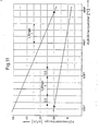
- Fig. 10 shows the process of heat removal with evaporation in a simplified schematic representation.
- the horizontally hatched area should schematically represent the proportion of pressurized water and the dotted area the proportion of steam.
- the left side should represent the pressurized water-steam mixture ratio when the pressurized water quantity is 1-, the right side with one of 1+.
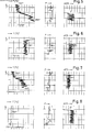
- FIG. 1 and 2 show an embodiment of a cooling unit for cooling wide flat rolled stock, e.g. Hot wide strip.
- the cooling unit consists primarily of the pressure chamber of the convection cooling section, the convection pressure chamber (1), with the accumulation edges (7) and (8) and secondarily from the pressure chamber of the evaporative cooling section, the evaporation pressure chamber (2), with the accumulation edges (9) and (10), plus the pressurized water line (3), the pressurized water valve (4), the pressurized water inflow control valve (5), the inflows (6), the lower part of the cooling unit (1), the upper part of the cooling unit (12), a seal (13) and the turbulence enhancer (15) Flow indicator (16), the laterally variable storage edges (17), the water and condensation box (19), plus the showers (20), the pressurized water / steam mixture retaining elements (21) and the water and condensate drains (22)
- the pressurized water flows from the pressurized water line (3), via the pressurized water valve (4) with approx. 80% and via the pressurized water inflow control valve (5) with approx. 20%, through the inflows (6) into the convection pressure chamber (1), is heated to the boiling point by the continuous, low-rolling rolling stock, the pressurized water / steam mixture generated flows over the accumulation edges (7) and ( 8) into the evaporation pressure chamber (2), then cools - then the hot rolled rolling stock by removing heat, which the pressurized water-steam mixture extracts from the rolling stock as evaporation heat, and leaves the cooling unit through the accumulation edges (9) and (10) .
- the damming edges (7) and (8) are arranged to make it difficult for the pressurized water to leave the convection pressure chamber (1) and to separate the process of heat removal in the two pressure rooms (1) and (2) so that the physical possibility is created to keep the extraction of heat from the hot rolled material stable by convection and evaporation (bubble and film boiling) and to be able to use it as optimally as possible.
- the steam portion of the pressurized water / steam mixture flowing out through the accumulation edges (9) and (10) is condensed on the underside between the roller table rollers with showers (20) for wide flat rolled stock and on the top by means of the pressurized water / steam mixture retaining elements (21 ), e.g. in the form of movable flaps, led into the water and condensation box (19) in the upper part (12) and condensed there with showers (20). Water and condensate drain through the opening (22).
- FIG. 3 and 4 show an embodiment of a cooling unit for cooling section steel, e.g. I-, L-profiles, reinforcement steel, wire rod.
- a cooling unit for cooling section steel e.g. I-, L-profiles, reinforcement steel, wire rod.
- the cooling unit for this consists in the main parts of the same parts as described for the cooling unit for wide flat rolled stock, with reference to FIGS. 1 and 2.
- the cooling unit body is, however, preferably in one piece (14), as a result of which the pressurized water / steam mixture emerging from the storage edges (9) and (10) flows directly into the water and condensation box (19).
- a connecting piece (18) is shown, with which two or more cooling units can be connected, if no air should be able to reach the surface of the rolling stock during cooling in the pressurized water.
Applications Claiming Priority (2)
| Application Number | Priority Date | Filing Date | Title |
|---|---|---|---|
| DE19863626741 DE3626741A1 (de) | 1986-08-07 | 1986-08-07 | Kuehlaggregat und verfahren zum abkuehlen walzwarmen walzguts, mit/ohne direktpatentieren, in druckkuehlwasser |
| DE3626741 | 1986-08-07 |
Publications (2)
| Publication Number | Publication Date |
|---|---|
| EP0266302A1 true EP0266302A1 (fr) | 1988-05-04 |
| EP0266302B1 EP0266302B1 (fr) | 1993-09-29 |
Family
ID=6306869
Family Applications (1)
| Application Number | Title | Priority Date | Filing Date |
|---|---|---|---|
| EP87710010A Expired - Lifetime EP0266302B1 (fr) | 1986-08-07 | 1987-08-07 | Agrégat de refroidissement et procédé pour refroidir des matières à laminer à chaud avec/sans patentage directe à pression hydraulique |
Country Status (4)
| Country | Link |
|---|---|
| EP (1) | EP0266302B1 (fr) |
| AT (1) | AT390273B (fr) |
| DE (2) | DE3626741A1 (fr) |
| ES (1) | ES2046213T3 (fr) |
Cited By (2)
| Publication number | Priority date | Publication date | Assignee | Title |
|---|---|---|---|---|
| EP0875304A2 (fr) * | 1997-05-02 | 1998-11-04 | Sms Schloemann-Siemag Aktiengesellschaft | Procédé et agrégat de refroidissement pour refroidir des produits de laminage chauds, notamment des bandes larges laminées à chaud |
| CN104550275A (zh) * | 2014-12-26 | 2015-04-29 | 钢铁研究总院 | 一种用于热轧高强度钢筋的水雾汽化冷却装置及方法 |
Families Citing this family (4)
| Publication number | Priority date | Publication date | Assignee | Title |
|---|---|---|---|---|
| DE3708128A1 (de) * | 1987-03-13 | 1988-09-22 | Krenn Walter | Verfahren und druckkuehlaggregat zum gefuehrten abkuehlen geformten, schweren bis leichten, heissen, durchlaufenden produktionsguts aus stahl und metall in druckwasser |
| DE4009228A1 (de) * | 1990-03-22 | 1991-09-26 | Krenn Walter | Verfahren und druckkuehlaggregat zum gleichzeitig unterschiedlichen abkuehlen ausgewaehlter bereiche durchlaufenden produktionsguts, mit flach- oder profilquerschnitt, aus stahl und anderem |
| DE4201295A1 (de) * | 1992-01-15 | 1993-07-22 | Thaelmann Schwermaschbau Veb | Vorrichtung zum fuehren und kuehlen von walzgut in drahtwalzbloecken |
| DE19850739A1 (de) * | 1998-11-04 | 2000-05-11 | Schloemann Siemag Ag | Verfahren und Vorrichtung zum Kühlen von walzwarmem Walzgut, insbesondere Warmbreitband |
Citations (5)
| Publication number | Priority date | Publication date | Assignee | Title |
|---|---|---|---|---|
| DE1925416A1 (de) * | 1968-03-12 | 1970-11-26 | Walter Krenn | Kuehlstrecke fuer Walzdraht od.dgl. |
| DE1608327A1 (de) * | 1968-03-12 | 1970-12-10 | Walter Krenn | Kuehlstrecke fuer Walzdraht od.dgl. |
| DE2440415A1 (de) * | 1974-04-10 | 1975-10-23 | Qualitaets Und Edelstahl Kom V | Verfahren und vorrichtung zur gesteuerten abkuehlung von walzgut, insbesondere von stabmaterial |
| US4136544A (en) * | 1976-08-31 | 1979-01-30 | Showa Electric Wire & Cable Co., Ltd. | Cooling tubes for wire stocks |
| DE3043117A1 (de) * | 1968-03-12 | 1982-07-01 | Walter 4330 Mülheim Krenn | Kuehlstrecke fuer walzdraht oder stabmaterial |
-
1986
- 1986-08-07 DE DE19863626741 patent/DE3626741A1/de not_active Withdrawn
-
1987
- 1987-07-30 AT AT0192987A patent/AT390273B/de not_active IP Right Cessation
- 1987-08-07 ES ES198787710010T patent/ES2046213T3/es not_active Expired - Lifetime
- 1987-08-07 DE DE87710010T patent/DE3787612D1/de not_active Expired - Fee Related
- 1987-08-07 EP EP87710010A patent/EP0266302B1/fr not_active Expired - Lifetime
Patent Citations (5)
| Publication number | Priority date | Publication date | Assignee | Title |
|---|---|---|---|---|
| DE1925416A1 (de) * | 1968-03-12 | 1970-11-26 | Walter Krenn | Kuehlstrecke fuer Walzdraht od.dgl. |
| DE1608327A1 (de) * | 1968-03-12 | 1970-12-10 | Walter Krenn | Kuehlstrecke fuer Walzdraht od.dgl. |
| DE3043117A1 (de) * | 1968-03-12 | 1982-07-01 | Walter 4330 Mülheim Krenn | Kuehlstrecke fuer walzdraht oder stabmaterial |
| DE2440415A1 (de) * | 1974-04-10 | 1975-10-23 | Qualitaets Und Edelstahl Kom V | Verfahren und vorrichtung zur gesteuerten abkuehlung von walzgut, insbesondere von stabmaterial |
| US4136544A (en) * | 1976-08-31 | 1979-01-30 | Showa Electric Wire & Cable Co., Ltd. | Cooling tubes for wire stocks |
Cited By (4)
| Publication number | Priority date | Publication date | Assignee | Title |
|---|---|---|---|---|
| EP0875304A2 (fr) * | 1997-05-02 | 1998-11-04 | Sms Schloemann-Siemag Aktiengesellschaft | Procédé et agrégat de refroidissement pour refroidir des produits de laminage chauds, notamment des bandes larges laminées à chaud |
| EP0875304A3 (fr) * | 1997-05-02 | 2002-01-02 | SMS Demag AG | Procédé et agrégat de refroidissement pour refroidir des produits de laminage chauds, notamment des bandes larges laminées à chaud |
| CN104550275A (zh) * | 2014-12-26 | 2015-04-29 | 钢铁研究总院 | 一种用于热轧高强度钢筋的水雾汽化冷却装置及方法 |
| CN104550275B (zh) * | 2014-12-26 | 2016-07-06 | 钢铁研究总院 | 一种用于热轧高强度钢筋的水雾汽化冷却装置及方法 |
Also Published As
| Publication number | Publication date |
|---|---|
| EP0266302B1 (fr) | 1993-09-29 |
| ATA192987A (de) | 1989-09-15 |
| AT390273B (de) | 1990-04-10 |
| DE3787612D1 (de) | 1993-11-04 |
| ES2046213T3 (es) | 1994-02-01 |
| DE3626741A1 (de) | 1988-02-18 |
Similar Documents
| Publication | Publication Date | Title |
|---|---|---|
| DE1752549A1 (de) | Verfahren und Vorrichtung zum Kuehlen von gewalzten Metallstreifen | |
| AT390273B (de) | Kuehlaggregat und verfahren zum abkuehlen walzwarmen walzguts | |
| DD299419A5 (de) | Verfahren, gefaess und einrichtung zur kontinuierlichen oder intermittierenden beschichtung von gegenstaenden | |
| DE1608327C3 (de) | Kuhlstrecke fur Walzdraht oder Stabmatenal | |
| DE3006544A1 (de) | Verfahren zur automatischen steuerung oder einstellung der breite einer bramme bzw. metallplatte beim warmvorwalzen derselben | |
| EP0998993B1 (fr) | Procédé et dispositif pour refroidir des produits de laminage chauds, notamment des bandes larges laminées à chaud | |
| DE3518925A1 (de) | Verfahren zum kontrollierten stab- und drahtwalzen legierter staehle | |
| DE1452168A1 (de) | Verfahren zur UEberwachung des Abkuehlens von Grobblechen nach durch theoretische Untersuchungen gefundenen Formeln | |
| DE102009048567B4 (de) | Verfahren und Anordnung zum Kühlen eines Gießstrangs in einer Stranggießanlage | |
| DE2440415A1 (de) | Verfahren und vorrichtung zur gesteuerten abkuehlung von walzgut, insbesondere von stabmaterial | |
| EP0287503B1 (fr) | Procédé et groupe frigorifique de pression pour refroidir un produit continu | |
| DE2102800B2 (de) | Anlage zur thermischen behandlung von walzerzeugnissen im kuehlmittelstrom | |
| DE2457293A1 (de) | Floatverfahren und vorrichtung zu seiner durchfuehrung | |
| DE3112673C2 (de) | Kühlvorrichtung für Metall-, insbesondere für Stahlgießstränge | |
| EP0875304B1 (fr) | Procédé et agrégat de refroidissement pour refroidir des produits de laminage chauds, notamment des bandes larges laminées à chaud | |
| EP1943364A1 (fr) | Procédé et installation pour la transformation à sec d une structure de matériau de produits semi-finis | |
| DE4009228A1 (de) | Verfahren und druckkuehlaggregat zum gleichzeitig unterschiedlichen abkuehlen ausgewaehlter bereiche durchlaufenden produktionsguts, mit flach- oder profilquerschnitt, aus stahl und anderem | |
| DE2529272A1 (de) | Verfahren und vorrichtung fuer die behandlung von walzdraht | |
| DE262970C (fr) | ||
| DE1583418B2 (de) | Vorrichtung zum fortlaufenden abschrecken von schienen | |
| DE102017202909A1 (de) | Verfahren und Anlage zur Herstellung eines metallischen Bandes | |
| DE2426828B2 (de) | Vorrichtung zum Kuhlen von Stangenmaterial | |
| DE2815090A1 (de) | Verfahren und vorrichtung zur herstellung von walzdraht aus hartem stahl | |
| DE2152514A1 (de) | Verfahren zur waermebehandlung von walzdraht | |
| EP4351812A1 (fr) | Procédé de fabrication d'un acier micro-allié, acier micro-allié produit à l'aide du procédé et installation combinée de coulée/laminage |
Legal Events
| Date | Code | Title | Description |
|---|---|---|---|
| PUAI | Public reference made under article 153(3) epc to a published international application that has entered the european phase |
Free format text: ORIGINAL CODE: 0009012 |
|
| AK | Designated contracting states |
Kind code of ref document: A1 Designated state(s): AT BE DE ES FR GB IT SE |
|
| RAP1 | Party data changed (applicant data changed or rights of an application transferred) |
Owner name: KRENN, WALTER, DIPL.-ING. |
|
| RAP3 | Party data changed (applicant data changed or rights of an application transferred) |
Owner name: KRENN, WALTER, DIPL.-ING. |
|
| RIN1 | Information on inventor provided before grant (corrected) |
Inventor name: KRENN, WALTER, DIPL.-ING. |
|
| 17P | Request for examination filed |
Effective date: 19890509 |
|
| 17Q | First examination report despatched |
Effective date: 19900619 |
|
| 17Q | First examination report despatched |
Effective date: 19910226 |
|
| GRAA | (expected) grant |
Free format text: ORIGINAL CODE: 0009210 |
|
| AK | Designated contracting states |
Kind code of ref document: B1 Designated state(s): BE DE ES FR GB IT SE |
|
| PG25 | Lapsed in a contracting state [announced via postgrant information from national office to epo] |
Ref country code: SE Effective date: 19930929 |
|
| REF | Corresponds to: |
Ref document number: 3787612 Country of ref document: DE Date of ref document: 19931104 |
|
| ITF | It: translation for a ep patent filed |
Owner name: SANDRO BASEVI |
|
| REG | Reference to a national code |
Ref country code: ES Ref legal event code: FG2A Ref document number: 2046213 Country of ref document: ES Kind code of ref document: T3 |
|
| GBT | Gb: translation of ep patent filed (gb section 77(6)(a)/1977) |
Effective date: 19940104 |
|
| ET | Fr: translation filed | ||
| PLBE | No opposition filed within time limit |
Free format text: ORIGINAL CODE: 0009261 |
|
| STAA | Information on the status of an ep patent application or granted ep patent |
Free format text: STATUS: NO OPPOSITION FILED WITHIN TIME LIMIT |
|
| 26N | No opposition filed | ||
| PGFP | Annual fee paid to national office [announced via postgrant information from national office to epo] |
Ref country code: FR Payment date: 19970725 Year of fee payment: 11 |
|
| PGFP | Annual fee paid to national office [announced via postgrant information from national office to epo] |
Ref country code: GB Payment date: 19970729 Year of fee payment: 11 |
|
| PGFP | Annual fee paid to national office [announced via postgrant information from national office to epo] |
Ref country code: BE Payment date: 19970808 Year of fee payment: 11 |
|
| PGFP | Annual fee paid to national office [announced via postgrant information from national office to epo] |
Ref country code: ES Payment date: 19970811 Year of fee payment: 11 |
|
| PGFP | Annual fee paid to national office [announced via postgrant information from national office to epo] |
Ref country code: DE Payment date: 19980806 Year of fee payment: 12 |
|
| PG25 | Lapsed in a contracting state [announced via postgrant information from national office to epo] |
Ref country code: GB Free format text: LAPSE BECAUSE OF NON-PAYMENT OF DUE FEES Effective date: 19980807 |
|
| PG25 | Lapsed in a contracting state [announced via postgrant information from national office to epo] |
Ref country code: ES Free format text: LAPSE BECAUSE OF NON-PAYMENT OF DUE FEES Effective date: 19980808 |
|
| PG25 | Lapsed in a contracting state [announced via postgrant information from national office to epo] |
Ref country code: BE Free format text: LAPSE BECAUSE OF NON-PAYMENT OF DUE FEES Effective date: 19980831 |
|
| BERE | Be: lapsed |
Owner name: KRENN WALTER Effective date: 19980831 |
|
| GBPC | Gb: european patent ceased through non-payment of renewal fee |
Effective date: 19980807 |
|
| PG25 | Lapsed in a contracting state [announced via postgrant information from national office to epo] |
Ref country code: FR Free format text: LAPSE BECAUSE OF NON-PAYMENT OF DUE FEES Effective date: 19990430 |
|
| REG | Reference to a national code |
Ref country code: FR Ref legal event code: ST |
|
| PG25 | Lapsed in a contracting state [announced via postgrant information from national office to epo] |
Ref country code: DE Free format text: LAPSE BECAUSE OF NON-PAYMENT OF DUE FEES Effective date: 20000601 |
|
| REG | Reference to a national code |
Ref country code: ES Ref legal event code: FD2A Effective date: 19990910 |
|
| PG25 | Lapsed in a contracting state [announced via postgrant information from national office to epo] |
Ref country code: IT Free format text: LAPSE BECAUSE OF NON-PAYMENT OF DUE FEES;WARNING: LAPSES OF ITALIAN PATENTS WITH EFFECTIVE DATE BEFORE 2007 MAY HAVE OCCURRED AT ANY TIME BEFORE 2007. THE CORRECT EFFECTIVE DATE MAY BE DIFFERENT FROM THE ONE RECORDED. Effective date: 20050807 |