EP0265995B2 - Dispositif de régulation des moyens d'entraínement dans le bobinage de fils sur machines textiles - Google Patents
Dispositif de régulation des moyens d'entraínement dans le bobinage de fils sur machines textiles Download PDFInfo
- Publication number
- EP0265995B2 EP0265995B2 EP87202000A EP87202000A EP0265995B2 EP 0265995 B2 EP0265995 B2 EP 0265995B2 EP 87202000 A EP87202000 A EP 87202000A EP 87202000 A EP87202000 A EP 87202000A EP 0265995 B2 EP0265995 B2 EP 0265995B2
- Authority
- EP
- European Patent Office
- Prior art keywords
- drive source
- winding
- thread
- speed
- drive
- Prior art date
- Legal status (The legal status is an assumption and is not a legal conclusion. Google has not performed a legal analysis and makes no representation as to the accuracy of the status listed.)
- Expired - Lifetime
Links
Images
Classifications
-
- B—PERFORMING OPERATIONS; TRANSPORTING
- B65—CONVEYING; PACKING; STORING; HANDLING THIN OR FILAMENTARY MATERIAL
- B65H—HANDLING THIN OR FILAMENTARY MATERIAL, e.g. SHEETS, WEBS, CABLES
- B65H54/00—Winding, coiling, or depositing filamentary material
- B65H54/02—Winding and traversing material on to reels, bobbins, tubes, or like package cores or formers
- B65H54/40—Arrangements for rotating packages
- B65H54/42—Arrangements for rotating packages in which the package, core, or former is rotated by frictional contact of its periphery with a driving surface
-
- B—PERFORMING OPERATIONS; TRANSPORTING
- B65—CONVEYING; PACKING; STORING; HANDLING THIN OR FILAMENTARY MATERIAL
- B65H—HANDLING THIN OR FILAMENTARY MATERIAL, e.g. SHEETS, WEBS, CABLES
- B65H2701/00—Handled material; Storage means
- B65H2701/30—Handled filamentary material
- B65H2701/31—Textiles threads or artificial strands of filaments
Definitions
- the present invention relates to a device for regulating and controlling a thread-guide drive roll in a winding station of an automatic coner machine, comprising a three-phase drive source for rotating the thread-guide roll, and a variable-frequency inverter connected to an electric power supply line and to the drive source for supplying variable frequency alternating current to rotate the drive source, according to DE-A-2 827 812.
- the present invention relates to a device comprising a variable-frequency inverter which performs the functions of power transducer converting signals coming from a central control unit into electrical power signals suitable to drive the three-phase drive source in the desired way according to winding parameters.
- the variable-frequency inverter receives the start-up signal, it starts up the drive source with a pre-established and calibratable acceleration slope, and it brings it from zero speed to the steady-state running speed; also the steady-state running speed is pre-established and calibratable.
- variable-frequency inverter When the variable-frequency inverter receives the stop signal, it pilots the drive source with a pre-established and calibratable deceleration slope, and brings it from the steady-state running speed to zero speed.
- variable-frequency inverter When the variable-frequency inverter receives the revolution-direction-reversing signal, it pilots the drive source, obliging it to precise pre-established and calibratable motion values according to the requirements of a programmed cycle.
- Threads have been normally wound by friction for a long time.
- the bobbin, or cone during its winding process, is driven by being kept into contact with a drive roll, which revolves at a constant number of revolutions per minute.
- the cone when the cone is placed into contact with the drive roll, the cone is accelerated up to the peripheral speed of the same roll, which rotates at a constant winding speed.
- the cone, as well as the wound thread are stressed in a detrimental way, generating faulty lengths of thread, and inaccurate windings, which cause difficulties during the unwinding processes downstream the production process.
- the roll which drives the cone, and the thread-guide unit constitute a single machine element, which is the fluted drum.
- the cone frequently undergoes sudden speed changes, which cause disarrangements in turns in the cross winding, due to the too sudden and irregular accelerations, which cause, furthermore, more or less marked slippings, which can easily cause the scorching and sticking of outer fibrils in the threads, due to local overheating. Said stickings cause missed intakes of the cone thread end at the beginning of the knotting cycle, with decreases in the machine efficiency.
- the thread turn disarrangements can easily generate cone formation defects, which lead to difficulties during the unwinding process run in the manufacturing processes downstream the coning.
- the outer rim of the pulley made from a non-metallic material, as well as the contact surfaces of the pulley keyed on the drive shaft and of the pulley keyed on the shaft of the fluted roll undergo abrasion and changes in their surface characteristics, due to the effect of the relative sliding and of the local heating, which repeatedly occur at each start-up.
- the above affects the friction coefficient, which undergoes changes over time, not securing evenness and constancy in results.
- the present invention aims to overcome the above drawbacks, eliminating the damages caused to the collected thread during the whole winding process, and it furthermore also aims to prevent any faults from arising in thread layers or positions, allowing a precision winding to be carried out, which is also characterized by optimum unwinding properties.
- a compact thread package is thus to be obtained, which is characterized by outstanding unwinding properties, free from overlapping defects, and suitable for all uses in the manufacturing processes downstream the coning.
- the device of the invention makes it possible to conform the acceleration slope to the dynamic behaviour of the cone-drive roll system.
- the cone is started up at each re-winding beginning, without slippings, independently of the diameter of the thread package, which increases to the desired size, as required by the production process, is reached.
- the device of the present invention makes it possible as well to control also the deceleration ramp of the cone in contact with the drive roll, preventing that slippings may arise, in order not to have disarrangements in the turns, or localized scorchings in the fibrils of the collected thread.
- the device of DE-A-2 827 812 provides for recovering energy during the braking step, so that the total energy consumption of a winding machine having a plurality of winding stations can be considerably reduced.
- the synchronous motor that rotates the package is caused to act as a generator for feeding the asynchronous motor that drives the thread laying traverse mechanism of the winding unit. This allows to disconnect the package braking motor from the electric power supply line and to accelerate braking of the rotating package.
- Such a device is suitable only for winding units provided with two separate motors, namely one motor for rotating the package or cone and another motor for driving the traverse mechanism.
- the "energy saving" factor is to be taken into consideration as a determining factor in the importance of the technical options in the field of use of the device of the present invention.
- the extent of the energy saving which obtained by using the device of the present invention is such to take the attention of the user to this subject and to this technique, which allows, together with considerable operational savings, even technically simpler and functionally better solutions to be obtained.
- the device according to the invention makes it possible, in fact, to achieve a working speed for each individual winding station, which is variable from station to station, and with the possibility of comparably precise and fast regulations. It makes it possible to maintain the steady-state running speed constantly equal to the pre-established value, which can be calibrated by using the speed-monitoring probe-wheel keyed on the drive shafts and capable of performing an action on the drive force transmission path. Furthermore, the regulation impulses exert their influence on the cone winding speeds in real time; in such a way, the regulating circuit operates in a comparably fast way, and can therefore tend to a correct regulation.
- the device maintains the speed of the drive roll constant within narrow limits, and makes it possible as well to obtain a perfect repeatibility over time in the acceleration slopes according to pre-established and calibratable values, such as not to cause slippings between the drive roll and the cone, whichever the size of this latter is, between the winding beginning and the winding end.
- variable-frequency inverter in accomplishing the pre-established speed is, per se , very high; it is therefore unnecessary to prefer the use of such speed sensor devices as speedometer dynamos, and the like, to accomplish a closed feed-back loop which increases the precision in the steady-state speed, in the acceleration slopes, and increases the operating reliability.
- the device of the present invention makes it possible as well to regulate the speed for each winding station; or it makes it possible to regulate the speed to equal values for a partial or total number of winding stations along the whole machine operating front, to increase the flexibility of the production process, with no need of use of mechanical actions, such as belt changes, pulley changes, and the like. All of the speed levels can be digitally pre-established and are calibratable, by simple and fast procedures.
- the device makes it possible as well to obtain a uniformity in the start-ups and in the winding speeds between the various winding stations, and at different diameters of the cone being wound. All the above enables the user to achieve better slub catching qualities, with the slub catching being calibrated on coning parameters constant with time.
- variable-frequency inverter conforms always the power to the load, even during the start-up step.
- the reversal or the motor running direction can be performed without the use of contactors, by simply varying, at the level of electronic logic, the order of generation of the phases.
- the electrical braking of the motor is performed, and both fast and gradual speed changes are accomplished, according to the requirements of the production cycle.
- the three-phase drive source feeds, through a variable-frequency inverter, the direct-current power supply line, with an electric power equal to the recovered kinetic energy less the various losses, these latter being of limited amount.
- the power excess transferred to the line, not used by the other variable-frequency inverters, can be dissipated through resistors, or it can be preferably transferred to the three-phase line, to be used for other purposes inside the factory, an integral energy recovery being thus achieved.
- the device of the present invention makes it possible to obtain, as above said, precise drives of the cone under formation, which favour the automation of the winding station, in that the motion transmission members, as a whole, are simplified.
- This all can be understood by simply considering the elimination of the block- or disk-brake, and the elimination of the mechanical motion reversing device, which are replaced by electronic devices, whose precision is higher.
- a uniformity is obtained in the controls, as a whole, and in the operating areas of the collection stations, and, furthermore, considerable savings in stop and start-up times, frequently present throughout the cone formation cycle, are achieved.
- a further advantage provided by the device of the present invention is the elimination of the noise in the mechanical of motion-transmitting elements, such as clutch wheels. These latter increase their eccentricity with time, generating vibrational phenomena which, in their turn, cause a noisy running of the machine, because the sound levels overlap to each other, and increase in amplitude, endangering the health of the attending workmen.
- the possibility can be obtained as well, of disengaging the knotting cycle from the braking of the cone and of the drive roll.
- the value of the kinetic energy of the cone can be computed. It becomes thus possible, after a breakage of the thread being coned, or as a consequence of the cutting by the slubs, to disengage the braking of the cone and of the roll from the mechanical knotting cycle, for example, by making the braking action begin in advance relatively to the knotting cycle, by a time which is a function of the kinetic energy of the cone.
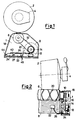
- 8 is a three-phase drive source provided to drive an individual winding station; 1 is the individual winding station; 6 is the drive roll, which supplies both the shift of the reciprocating movement of the thread, and the revolution motion of the cone 2 under formation, until the desired diameter of the thread package is obtained; 10 is a toothed belt provided to accomplish a positive transmission between a drive shaft 16 and the thread-guide roll 6; 2 is the cross-wound cone under formation; 4 is a cone-holder arm, which supports the cone 2 as the diameter thereof increases; 12 is a probe cooperating with a wheel 14 to monitor the speed during the whole cycle of cone formation; 14 is the wheel keyed on the drive shaft 16, which, in cooperation with the probe 12 sends, instant by instant, the speed monitoring data, to a central unit 24; 16 is the drive shaft on which the pulley driving the toothed belt 10 is keyed; 18 is an upper support of the individual winding station; 20 are the helical grooves, whose inclination angle corresponds to the crossing helical turns
- the device operates as follows.
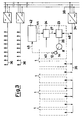
- the three-phase drive source 8 is mechanically stationary, and does not receive electrical power from the cable 26 of connection with the variable-frequency inverter 23.
- direct-current electrical line 36 which runs along the whole operating front of the winding machine to supply electrical power to the winding positions, the feed voltage is present.
- the following actions take place: through the connection cable 44 by the unit 42, containing stored in its storage memory the pre-established logic of the whole operating cycle, the signals of pre-selection of the accelerations and speeds which the user wants to obtain, instant by instant, during the whole operative winding cycle, are sent to the central control unit 24; at a desired time point, the unit 42 sends to the central unit 24 the operation start-up signal.
- the central control unit 24 sends, as a function of the pre-selection signals, to the variable-frequency inverter 23, through the connecting line 27, the signals for actuating start up of winding station 1.
- the variable-frequency inverter 23 draws electrical power from the direct-current electrical line 36 through the connection cable 46, to feed the three-phase drive source 8 through the connection cable 26.
- the drive source 8 starts to revolve, driving the probe-cooperating wheel 14 to revolve, and, through the toothed belt 10, drives to revolve the thread-guide fluted roll 6 too.
- the speed monitoring probe 12 in cooperation with the wheel 14 supplies to the central control unit 24, through the connection cable 40, instant by instant, the instant speed values.
- the central control unit 24 compares the pre-selection signal sent by the unit 42, with the value of the instant speed sent by the probe 12 and, by suitable processings, supplies to the variable-frequency inverter 23, through the connection cable 27, a new corrected drive signal.
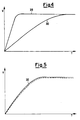
- the variable-frequency inverter 23, continuously conforming itself to the received signals, feeds and pilots, instant by instant, the three-phase drive source 8. In this way, it is possible to precisely follow pre-established acceleration curves and it is possible as well to maintain the value of the reached steady-state winding speed, it too being pre-established, within a prefixed range, independently from the applied loads; these latter being continuously variable during the whole winding cycle for the formation of a cone 2.
- a power is demanded and absorbed, which is larger than the demanded and absorbed power during the steady-state-speed winding process.
- Said acceleration power is stored as kinetic energy in the revolving parts.
- the unit 42 receives a signal indicating the need of a braking cycle, the unit 42 sends to the central control unit 24, through the connection cable 44, signals of preselection of the pre-established deceleration; at the desired moment, a braking-step-start-up signal is activated by the central control unit 24, which sends to the variable-frequency inverter 23, through the connection cable 27, the actuation signals.
- variable-frequency inverter 23 behaves such to transfer the electrical power from the drive source 8, which assumes the function of a generator actuated by the kinetic energy stored by the moving members, to the direct-current electrical line 36 through the following elements: the connection cable 26, the variable-frequency inverter 23, and the connection cable 46.
- the direct-current electrical line 36 has available a power not coming from the power supply unit 34. Such power can be collected and used by the other winding stations 1 connected to the same direct-current electrical line 36, thus an energy recovery - and hence an energy saving - being obtained.
- the energy excess can be transferred, through the power supply unit 34, to the external power supply three-phase line 38, or it can be dissipated through resistors provided inside the variable-frequency inverter 23.
- the signal generated, instant by instant, by the speed-monitoring probe 12 is sent, through the connection cable 48, to the unit 42 of the winding station 1, which processes it in order to compute the information of winding speed, and of length of thread wound on the cone under formation 2.
Claims (5)
- Dispositif de régulation et de commande d'un rouleau (6) d'entraínement guide-fil dans un poste (1) d'enroulement d'une machine de bobinage automatique de cônes, comprenant :une source (8) d'entraínement triphasée destinée à entraíner en rotation le rouleau (6) guide-fil,un inverseur (23) à fréquence variable relié à une ligne (36,38) d'alimentation en énergie électrique et à la source (8) d'entraínement et destiné à fournir un courant alternatif de fréquence variable à la source (8) d'entraínement, caractérisé en ce qu'il comprend, en outre:un ensemble sonde-roue (12,14) relié opérationnellement à la source (8) d'entraínement en vue de contrôler la vitesse de rotation réelle de cette dernière,des moyens (24,42) pour commander l'inverseur à fréquence variable afin de fournir des variations de vitesse d'enroulement de la source d'entraínement préétablies, lesdits moyens comprenant :une unité logique (42) enregistrant les valeurs des variations de vitesse d'enroulement pré-établies, etune unité de commande centrale destinée à comparer, instant par instant, les valeurs de vitesse réelle contrôlées par l'ensemble sonde-roue (12,14) aux valeurs enregistrées pré-établies et à corriger la commande de l'inverseur (23) à fréquence variable afin de fournir, instant par instant, une commande de source d'entraínement en conformité avec les valeurs pré-établies, lesdites valeurs pré-établies étant basées sur les valeurs de vitesse circonférentielle en conformité avec des valeurs de tailles de cônes spécifiques entre le début de l'enroulement et la fin de l'enroulement, la taille de cône pendant l'enroulement étant déterminée et contrôlée par l'ensemble sonde-roue et la commande à asservissement étant basée sur une comparaison instant par instant des valeurs de vitesse réelle mesurées et des valeurs des variations de vitesse d'enroulement pré-établies et enregistrées correspondant à la taille de cône contrôlée,et en ce qu'un raccordement de circuit réversible est prévu entre la source (8) d'entraínement et la ligne (36,38) d'alimentation en énergie électrique, de telle manière que, durant les étapes de freinage ou de décélération de ladite source (8) d'entraínement et dudit rouleau (6) guide-fil, la source (8) d'entraínement fournisse de l'énergie électrique à la ligne (36,38) d'alimentation en énergie électrique.
- Dispositif selon la revendication 1, caractérisé en ce que l'ensemble sonde-roue (12,14) est associé à l'arbre (16) de la source (8) d'entraínement et en ce que la source (8) d'entraínement est reliée opérationnellement au rouleau (6) guide-fil par l'intermédiaire d'un moyen de transmission positive de mouvement, tel qu'une courroie (10) dentée.
- Dispositif selon la revendication 1, caractérisé en ce que le rouleau (6) guide-fil est monté sur l'arbre (10) de la source (8) d'entraínement.
- Dispositif selon la revendication 1, caractérisé en ce que l'inverseur (23) à fréquence variable est disposé de façon à commander la rotation de la source (8) d'entraínement dans des sens de rotation opposés correspondant à l'enroulement et au déroulement du fil.
- Dispositif selon la revendication 1, caractérisé en ce que l'ensemble sonde-roue (12,14) est relié à l'unité logique (42) et en ce que l'unité logique (42) traite les valeurs de vitesse entrantes pendant la rotation du-rouleau (6) guide-fil afin de déterminer la longueur du fil réellement enroulé.
Priority Applications (1)
| Application Number | Priority Date | Filing Date | Title |
|---|---|---|---|
| AT87202000T ATE62001T1 (de) | 1986-10-22 | 1987-10-19 | Vorrichtung zum regulieren der antriebsmittel beim wickeln von faeden in textilmaschinen. |
Applications Claiming Priority (2)
| Application Number | Priority Date | Filing Date | Title |
|---|---|---|---|
| IT2207786 | 1986-10-22 | ||
| IT22077/86A IT1198061B (it) | 1986-10-22 | 1986-10-22 | Apparecchiatura e procedimento per la regolazione dei comandi di azionamento nell'avvolgitura di fili in macchine tessili |
Publications (3)
| Publication Number | Publication Date |
|---|---|
| EP0265995A1 EP0265995A1 (fr) | 1988-05-04 |
| EP0265995B1 EP0265995B1 (fr) | 1991-03-27 |
| EP0265995B2 true EP0265995B2 (fr) | 2000-05-17 |
Family
ID=11191132
Family Applications (1)
| Application Number | Title | Priority Date | Filing Date |
|---|---|---|---|
| EP87202000A Expired - Lifetime EP0265995B2 (fr) | 1986-10-22 | 1987-10-19 | Dispositif de régulation des moyens d'entraínement dans le bobinage de fils sur machines textiles |
Country Status (7)
| Country | Link |
|---|---|
| US (1) | US4915314A (fr) |
| EP (1) | EP0265995B2 (fr) |
| AT (1) | ATE62001T1 (fr) |
| DE (1) | DE3768909D1 (fr) |
| ES (1) | ES2022309T5 (fr) |
| GR (2) | GR3001839T3 (fr) |
| IT (1) | IT1198061B (fr) |
Cited By (1)
| Publication number | Priority date | Publication date | Assignee | Title |
|---|---|---|---|---|
| CZ306486B6 (cs) * | 2015-12-18 | 2017-02-08 | Technická univerzita v Liberci | Způsob a zařízení k navíjení příze na cívku na textilních strojích vyrábějících přízi |
Families Citing this family (7)
| Publication number | Priority date | Publication date | Assignee | Title |
|---|---|---|---|---|
| JP2501978B2 (ja) * | 1991-09-17 | 1996-05-29 | 村田機械株式会社 | 自動ワインダの巻取速度制御方法 |
| JP3195822B2 (ja) * | 1992-05-18 | 2001-08-06 | 津田駒工業株式会社 | 整経機の走行距離計測装置と、整経機の停止制御装置 |
| DE4339217A1 (de) * | 1993-11-18 | 1995-05-24 | Schlafhorst & Co W | Verfahren zum Steuern einer Spulstelle einer Spulmaschine bei Auflaufspulenwechsel und Spulstelle zur Durchführung des Verfahrens |
| DE19735581A1 (de) * | 1997-08-16 | 1999-02-18 | Schlafhorst & Co W | Spultrommelantrieb einer Kreuzspulen herstellenden Textilmaschine |
| DE29908962U1 (de) * | 1999-05-21 | 1999-09-02 | Neumag Gmbh | Aufspulmaschine |
| JP6723801B2 (ja) * | 2016-04-12 | 2020-07-15 | シロキ工業株式会社 | 車両用開閉体駆動装置の組付判定方法 |
| DE102019128612A1 (de) * | 2019-10-23 | 2021-04-29 | Saurer Spinning Solutions Gmbh & Co. Kg | Textilmaschine |
Family Cites Families (13)
| Publication number | Priority date | Publication date | Assignee | Title |
|---|---|---|---|---|
| DE2200627A1 (de) * | 1971-01-26 | 1973-01-25 | Spinnereimaschb Karl Marx Stad | Vorrichtung zum konstanthalten der aufwickelgeschwindigkeit, insbesondere an aufwickelmaschinen fuer synthetische faeden |
| DE2319128A1 (de) * | 1973-04-16 | 1974-10-24 | Karlsruhe Augsburg Iweka | Elektrischer antrieb fuer chemiefaser-maschinen |
| DE2606093C2 (de) * | 1975-08-08 | 1984-05-10 | Barmag Barmer Maschinenfabrik Ag, 5630 Remscheid | Aufspulmaschine |
| JPS6023065B2 (ja) * | 1978-02-16 | 1985-06-05 | 東レ株式会社 | 糸条巻取装置 |
| DE2811158B1 (de) * | 1978-03-15 | 1979-08-02 | Barmag Barmer Maschf | Verfahren zum gemeinsamen Steuern der Motoren fuer Changiereinrichtungen und Spulenantrieb an einer vielstelligen Spulmaschine und Steuereinrichtung zum Durchfuehren des Verfahrens |
| DE2827812C3 (de) * | 1978-06-24 | 1981-06-11 | Barmag Barmer Maschinenfabrik Ag, 5630 Remscheid | Spulmaschine |
| US4394986A (en) * | 1981-05-13 | 1983-07-26 | Toray Industries, Inc. | Yarn winding apparatus |
| DE3236942A1 (de) * | 1981-10-09 | 1983-04-28 | Barmag Barmer Maschinenfabrik Ag, 5630 Remscheid | Aufspulvorrichtung fuer synthetische faeden |
| JPS5878953A (ja) * | 1981-11-04 | 1983-05-12 | Teijin Ltd | 糸条巻取装置 |
| US4548366A (en) * | 1982-05-17 | 1985-10-22 | Rieter Machine Works, Ltd. | Chuck drive system |
| US4566642A (en) * | 1984-12-07 | 1986-01-28 | Rieter Machine Works Ltd. | Method and apparatus for monitoring chuck overspeed |
| EP0196090B2 (fr) * | 1985-03-28 | 1995-06-14 | TEIJIN SEIKI CO. Ltd. | Détecteur d'anomalie dans un dispositif de bobinage de fil |
| EP0202624B1 (fr) * | 1985-05-17 | 1990-08-08 | TEIJIN SEIKI CO. Ltd. | Machine pour enrouler du fil avec entraînement de la broche |
-
1986
- 1986-10-22 IT IT22077/86A patent/IT1198061B/it active
-
1987
- 1987-10-19 ES ES87202000T patent/ES2022309T5/es not_active Expired - Lifetime
- 1987-10-19 DE DE8787202000T patent/DE3768909D1/de not_active Expired - Fee Related
- 1987-10-19 EP EP87202000A patent/EP0265995B2/fr not_active Expired - Lifetime
- 1987-10-19 AT AT87202000T patent/ATE62001T1/de not_active IP Right Cessation
-
1989
- 1989-08-22 US US07/396,764 patent/US4915314A/en not_active Expired - Lifetime
-
1991
- 1991-04-24 GR GR91400525T patent/GR3001839T3/el unknown
-
2000
- 2000-07-31 GR GR20000401768T patent/GR3034076T3/el not_active IP Right Cessation
Cited By (1)
| Publication number | Priority date | Publication date | Assignee | Title |
|---|---|---|---|---|
| CZ306486B6 (cs) * | 2015-12-18 | 2017-02-08 | Technická univerzita v Liberci | Způsob a zařízení k navíjení příze na cívku na textilních strojích vyrábějících přízi |
Also Published As
| Publication number | Publication date |
|---|---|
| DE3768909D1 (de) | 1991-05-02 |
| GR3034076T3 (en) | 2000-11-30 |
| GR3001839T3 (en) | 1992-11-23 |
| EP0265995A1 (fr) | 1988-05-04 |
| ATE62001T1 (de) | 1991-04-15 |
| IT1198061B (it) | 1988-12-21 |
| ES2022309T5 (es) | 2000-10-16 |
| US4915314A (en) | 1990-04-10 |
| ES2022309B3 (es) | 1991-12-01 |
| IT8622077A0 (it) | 1986-10-22 |
| EP0265995B1 (fr) | 1991-03-27 |
Similar Documents
| Publication | Publication Date | Title |
|---|---|---|
| US4805844A (en) | Method and apparatus for monitoring and controlling winding operation of a winding station in a textile winding machine | |
| US4548366A (en) | Chuck drive system | |
| EP0265995B2 (fr) | Dispositif de régulation des moyens d'entraínement dans le bobinage de fils sur machines textiles | |
| US4069985A (en) | Winding machines with contact roller driven by synchronous motor or asynchronous motor | |
| JP3637356B2 (ja) | フィラメントの巻取り方法及び装置 | |
| JP2014122117A (ja) | リボン巻を防止する方法及び綾巻きパッケージの巻取り装置 | |
| US5035370A (en) | Method and apparatus for avoiding ribbon windings when winding a cross-wound bobbin | |
| EP3383780B1 (fr) | Procédé pour positionner une broche avec précision dans un enrouleur automatique de type tourelle | |
| US5112000A (en) | Apparatus for controlling the contact pressure and/or relative motion between a bobbin cylinder and a bobbin | |
| US5735473A (en) | Method and apparatus for avoiding ribbon windings | |
| EP0311106B1 (fr) | Métier à filer | |
| JP6602590B2 (ja) | 巻取りパッケージを巻成する方法及び装置 | |
| JPH07112903B2 (ja) | 綾巻きボビンの巻糸において重ね巻きを阻止する方法および装置 | |
| EP0952245B1 (fr) | Machine de torsion multiple avec broche à entraínement individuel | |
| JP2716837B2 (ja) | 自動ワインダ | |
| US3937409A (en) | Electric drive for fiber or thread winding machines and method of operating winding machines | |
| JP4638584B2 (ja) | スピンドルに締め付け装置を有するリング精紡機 | |
| US3358433A (en) | Collection of synthetic polymeric yarns or filaments | |
| JP2000026021A (ja) | 綾巻きボビンを作製する繊維機械の作動方法 | |
| US3973739A (en) | Winding apparatus | |
| JP4085850B2 (ja) | 糸条巻取機におけるモータの制御装置 | |
| EP3746387B1 (fr) | Procédé permettant de positionner précisément une broche dans un enrouleur automatique de type à tourelle | |
| JPH1181062A (ja) | 糸条巻取機 | |
| JP3500413B2 (ja) | トラバース装置 | |
| RU2037460C1 (ru) | Машина для непрерывной намотки нити |
Legal Events
| Date | Code | Title | Description |
|---|---|---|---|
| PUAI | Public reference made under article 153(3) epc to a published international application that has entered the european phase |
Free format text: ORIGINAL CODE: 0009012 |
|
| AK | Designated contracting states |
Kind code of ref document: A1 Designated state(s): AT BE CH DE ES FR GB GR LI LU NL SE |
|
| RAP1 | Party data changed (applicant data changed or rights of an application transferred) |
Owner name: SAVIO S.P.A. |
|
| 17P | Request for examination filed |
Effective date: 19880530 |
|
| 17Q | First examination report despatched |
Effective date: 19891009 |
|
| GRAA | (expected) grant |
Free format text: ORIGINAL CODE: 0009210 |
|
| AK | Designated contracting states |
Kind code of ref document: B1 Designated state(s): AT BE CH DE ES FR GB GR LI LU NL SE |
|
| REF | Corresponds to: |
Ref document number: 62001 Country of ref document: AT Date of ref document: 19910415 Kind code of ref document: T |
|
| ET | Fr: translation filed | ||
| REF | Corresponds to: |
Ref document number: 3768909 Country of ref document: DE Date of ref document: 19910502 |
|
| PLBI | Opposition filed |
Free format text: ORIGINAL CODE: 0009260 |
|
| 26 | Opposition filed |
Opponent name: W. SCHLAFHORST & CO. Effective date: 19911211 |
|
| NLR1 | Nl: opposition has been filed with the epo |
Opponent name: W. SCHLAFHORST & CO. |
|
| REG | Reference to a national code |
Ref country code: GR Ref legal event code: FG4A Free format text: 3001839 |
|
| EPTA | Lu: last paid annual fee | ||
| EAL | Se: european patent in force in sweden |
Ref document number: 87202000.3 |
|
| PGFP | Annual fee paid to national office [announced via postgrant information from national office to epo] |
Ref country code: AT Payment date: 19961009 Year of fee payment: 10 |
|
| PG25 | Lapsed in a contracting state [announced via postgrant information from national office to epo] |
Ref country code: AT Free format text: LAPSE BECAUSE OF NON-PAYMENT OF DUE FEES Effective date: 19971019 |
|
| APCC | Communication from the board of appeal sent |
Free format text: ORIGINAL CODE: EPIDOS OBAPO |
|
| PGFP | Annual fee paid to national office [announced via postgrant information from national office to epo] |
Ref country code: SE Payment date: 19981006 Year of fee payment: 12 |
|
| PGFP | Annual fee paid to national office [announced via postgrant information from national office to epo] |
Ref country code: LU Payment date: 19981020 Year of fee payment: 12 |
|
| PGFP | Annual fee paid to national office [announced via postgrant information from national office to epo] |
Ref country code: NL Payment date: 19981028 Year of fee payment: 12 |
|
| APCC | Communication from the board of appeal sent |
Free format text: ORIGINAL CODE: EPIDOS OBAPO |
|
| APCC | Communication from the board of appeal sent |
Free format text: ORIGINAL CODE: EPIDOS OBAPO |
|
| APCC | Communication from the board of appeal sent |
Free format text: ORIGINAL CODE: EPIDOS OBAPO |
|
| REG | Reference to a national code |
Ref country code: CH Ref legal event code: PUE Owner name: SAVIO S.P.A. TRANSFER- SAVIO MACCHINE TESSILI S.P. |
|
| REG | Reference to a national code |
Ref country code: FR Ref legal event code: TP |
|
| APAE | Appeal reference modified |
Free format text: ORIGINAL CODE: EPIDOS REFNO |
|
| APCC | Communication from the board of appeal sent |
Free format text: ORIGINAL CODE: EPIDOS OBAPO |
|
| PG25 | Lapsed in a contracting state [announced via postgrant information from national office to epo] |
Ref country code: LU Free format text: LAPSE BECAUSE OF NON-PAYMENT OF DUE FEES Effective date: 19991019 |
|
| PG25 | Lapsed in a contracting state [announced via postgrant information from national office to epo] |
Ref country code: SE Free format text: THE PATENT HAS BEEN ANNULLED BY A DECISION OF A NATIONAL AUTHORITY Effective date: 19991030 |
|
| APCC | Communication from the board of appeal sent |
Free format text: ORIGINAL CODE: EPIDOS OBAPO |
|
| APAC | Appeal dossier modified |
Free format text: ORIGINAL CODE: EPIDOS NOAPO |
|
| PLAW | Interlocutory decision in opposition |
Free format text: ORIGINAL CODE: EPIDOS IDOP |
|
| PLAW | Interlocutory decision in opposition |
Free format text: ORIGINAL CODE: EPIDOS IDOP |
|
| BECA | Be: change of holder's address |
Free format text: 19990609 *SAVIO MACCHINE TESSILI S.P.A.:VIA UDINE 105, PORDENONE |
|
| BECH | Be: change of holder |
Free format text: 19990609 *SAVIO MACCHINE TESSILI S.P.A. |
|
| BECN | Be: change of holder's name |
Effective date: 19990609 |
|
| RAP2 | Party data changed (patent owner data changed or rights of a patent transferred) |
Owner name: SAVIO MACCHINE TESSILI S.P.A. |
|
| REG | Reference to a national code |
Ref country code: GB Ref legal event code: 732E |
|
| PUAH | Patent maintained in amended form |
Free format text: ORIGINAL CODE: 0009272 |
|
| STAA | Information on the status of an ep patent application or granted ep patent |
Free format text: STATUS: PATENT MAINTAINED AS AMENDED |
|
| PG25 | Lapsed in a contracting state [announced via postgrant information from national office to epo] |
Ref country code: NL Free format text: LAPSE BECAUSE OF NON-PAYMENT OF DUE FEES Effective date: 20000501 |
|
| NLT2 | Nl: modifications (of names), taken from the european patent patent bulletin |
Owner name: SAVIO MACCHINE TESSILI S.P.A. |
|
| 27A | Patent maintained in amended form |
Effective date: 20000517 |
|
| AK | Designated contracting states |
Kind code of ref document: B2 Designated state(s): AT BE CH DE ES FR GB GR LI LU NL SE |
|
| REG | Reference to a national code |
Ref country code: CH Ref legal event code: AEN Free format text: MAINTIEN DU BREVET DONT L'ETENDUE A ETE MODIFIEE |
|
| EUG | Se: european patent has lapsed |
Ref document number: 87202000.3 |
|
| NLV4 | Nl: lapsed or anulled due to non-payment of the annual fee |
Effective date: 20000501 |
|
| PG25 | Lapsed in a contracting state [announced via postgrant information from national office to epo] |
Ref country code: GR Free format text: THE PATENT HAS BEEN ANNULLED BY A DECISION OF A NATIONAL AUTHORITY Effective date: 20000731 |
|
| ET3 | Fr: translation filed ** decision concerning opposition | ||
| REG | Reference to a national code |
Ref country code: ES Ref legal event code: DC2A Kind code of ref document: T5 Effective date: 20000809 |
|
| PGFP | Annual fee paid to national office [announced via postgrant information from national office to epo] |
Ref country code: GB Payment date: 20001018 Year of fee payment: 14 |
|
| PGFP | Annual fee paid to national office [announced via postgrant information from national office to epo] |
Ref country code: GR Payment date: 20001027 Year of fee payment: 14 |
|
| PGFP | Annual fee paid to national office [announced via postgrant information from national office to epo] |
Ref country code: BE Payment date: 20001214 Year of fee payment: 14 |
|
| PG25 | Lapsed in a contracting state [announced via postgrant information from national office to epo] |
Ref country code: GB Free format text: LAPSE BECAUSE OF NON-PAYMENT OF DUE FEES Effective date: 20011019 |
|
| PG25 | Lapsed in a contracting state [announced via postgrant information from national office to epo] |
Ref country code: BE Free format text: LAPSE BECAUSE OF NON-PAYMENT OF DUE FEES Effective date: 20011031 |
|
| REG | Reference to a national code |
Ref country code: GB Ref legal event code: IF02 |
|
| BERE | Be: lapsed |
Owner name: SAVIO MACCHINE TESSILI S.P.A. Effective date: 20011031 |
|
| GBPC | Gb: european patent ceased through non-payment of renewal fee |
Effective date: 20011019 |
|
| PGFP | Annual fee paid to national office [announced via postgrant information from national office to epo] |
Ref country code: FR Payment date: 20021008 Year of fee payment: 16 |
|
| PGFP | Annual fee paid to national office [announced via postgrant information from national office to epo] |
Ref country code: ES Payment date: 20031128 Year of fee payment: 17 |
|
| PG25 | Lapsed in a contracting state [announced via postgrant information from national office to epo] |
Ref country code: FR Free format text: LAPSE BECAUSE OF NON-PAYMENT OF DUE FEES Effective date: 20040630 |
|
| REG | Reference to a national code |
Ref country code: FR Ref legal event code: ST |
|
| PG25 | Lapsed in a contracting state [announced via postgrant information from national office to epo] |
Ref country code: ES Free format text: LAPSE BECAUSE OF NON-PAYMENT OF DUE FEES Effective date: 20041020 |
|
| APAH | Appeal reference modified |
Free format text: ORIGINAL CODE: EPIDOSCREFNO |
|
| PGFP | Annual fee paid to national office [announced via postgrant information from national office to epo] |
Ref country code: DE Payment date: 20051014 Year of fee payment: 19 |
|
| PGFP | Annual fee paid to national office [announced via postgrant information from national office to epo] |
Ref country code: CH Payment date: 20051027 Year of fee payment: 19 |
|
| REG | Reference to a national code |
Ref country code: ES Ref legal event code: FD2A Effective date: 20041020 |
|
| PG25 | Lapsed in a contracting state [announced via postgrant information from national office to epo] |
Ref country code: LI Free format text: LAPSE BECAUSE OF NON-PAYMENT OF DUE FEES Effective date: 20061031 Ref country code: CH Free format text: LAPSE BECAUSE OF NON-PAYMENT OF DUE FEES Effective date: 20061031 |
|
| PG25 | Lapsed in a contracting state [announced via postgrant information from national office to epo] |
Ref country code: DE Free format text: LAPSE BECAUSE OF NON-PAYMENT OF DUE FEES Effective date: 20070501 |
|
| REG | Reference to a national code |
Ref country code: CH Ref legal event code: PL |