EP0265235A2 - Stranggiessen von Verbundmetall - Google Patents
Stranggiessen von Verbundmetall Download PDFInfo
- Publication number
- EP0265235A2 EP0265235A2 EP87309281A EP87309281A EP0265235A2 EP 0265235 A2 EP0265235 A2 EP 0265235A2 EP 87309281 A EP87309281 A EP 87309281A EP 87309281 A EP87309281 A EP 87309281A EP 0265235 A2 EP0265235 A2 EP 0265235A2
- Authority
- EP
- European Patent Office
- Prior art keywords
- magnetic field
- metal
- molten
- casting
- static magnetic
- Prior art date
- Legal status (The legal status is an assumption and is not a legal conclusion. Google has not performed a legal analysis and makes no representation as to the accuracy of the status listed.)
- Granted
Links
Images

Classifications
-
- B—PERFORMING OPERATIONS; TRANSPORTING
- B22—CASTING; POWDER METALLURGY
- B22D—CASTING OF METALS; CASTING OF OTHER SUBSTANCES BY THE SAME PROCESSES OR DEVICES
- B22D11/00—Continuous casting of metals, i.e. casting in indefinite lengths
- B22D11/007—Continuous casting of metals, i.e. casting in indefinite lengths of composite ingots, i.e. two or more molten metals of different compositions being used to integrally cast the ingots
Definitions
- This invention relates to a method of producing a composite metal material, typically a clad steel bloom or slab, comprising outer and inner layers of different compositions, namely of different chemical compositions, and more particularly to such a method wherein the composite metal material is produced by continuous casting; and to apparatus for us in such a method.
- an ingot for the core material is placed in a mold and molten steel of a composition different from that of the ingot is poured into the mold and allowed to solidify, thus producing a clad ingot. Because of its simplicity, this method has been used extensively at steelworks.
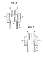
- Japanese Patent Publication 44(1969)-27361 two immersion nozzles of differing length are inserted into the pool of molten metal in the mold, the outlets of the two nozzles are located at different positions with respect to the direction of casting, and different types of molten metal are poured through the respective nozzles (see Figure 3).
- reference numeral 11 denotes the mold, while 12 and 13 denote the nozzles.
- the nozzles 12 and 13 are of different length and are used to pour different metals into the mold 11.
- Reference numeral 14 denotes the pool of molten metal in the mold 11, 15 denotes the outer layer of the composite material and 16 denotes the solidified portion of the inner layer thereof.
- reference numeral 21 denotes the mold
- 22 and 23 denote immersion nozzles having different lengths and introducing different metals into the mold 21.
- Reference numeral 24 denotes a pool of molten metal in the mold 21
- 25 denotes the outer layer of a composite steel material
- 26 denotes the solidified portion of an inner lalyer thereof
- 27 denotes the refractory partition.
- a preferred embodiment of the present invention provides a method which eliminates the aforesaid problems of the prior art and enable continuous casting of excellent quality composite metal material under stable operating conditions.
- the present invention provides a continuous casting method for producing composite metal material characterized in that molten metal is partitioned by a static magnetic field and each partitioned region is supplied with molten metal of a different composition.
- the molten metals of different comosition within the strand pool are separated by magnetic means and molten metals of different composition are to supplied upper and lower regions which are separated by magnetic field.
- molten metals of different composition are to supplied upper and lower regions which are separated by magnetic field.
- the inventors carried out various studies in order to find a solution to the problems of the prior art. As a result, they discovered that by forming a static magnetic field zone between the position at which molten metal is supplied to a relatively upward region of the mold and the position at which molten metal is supplied to a relatively downward region of the mold so that magnetic flux will extend perpendicularly to the direction of casting, the mixing of metals of different composition supplied at different positions can be effectively prevented.
- This invention was accomplished on the basis of this discovery.
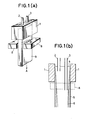
- the reference numeral 1 denotes a mold
- 2 and 3 denote respective immersion nozzles of different length used for pouring molten metals of different composition into the mold 1.
- Reference numeral 4 denotes a molten metal pool
- 5 denotes the outer layer of a composite steel material
- 6 denotes the solidified portion of an inner layer of the composite steel material.
- the reference numeral 8 denotes a magnet for producing a static magnetic field such that magnetic lines of force 10 extend perpendicularly to the direction of casting (A).
- the strand of cast metal is indicated at 9.
- a static magnetic field of predetermined strength is formed at a position below the level of the molten metal surface by the so-determined distance so as to extend across the full width of the cast metal and to extend in the direction of casting by a predetermined width, thereby to produce magnetic flux perpendicular to the direction of casting.
- the flow of molten metal which tends to be caused within the pool of molten metal by the pouring operation is restricted at this portion by the static magnetic field so that mixing of the upper and lower molten metal region which contact at this position can be minimized.
- the suppresion of the flow velocity of the molten metal increases in proportion as the density of magnetic flux is increased and the density of magnetic flux of the static magnetic field should be made as high as possible within the range that it does not hinder the casting operation.
- This restriction also increases in proportion as the width of the static magnetic filed in the direction of casting is increased.
- the static magnetic field zone may in some cases constitute a transition layer between the upper and lower region so that from this point of view, the width of the static magnetic field zone in the direction of casting should be made as small as possible.
- This invention relates to a production process in which such a "braking" effect is applied at a specified position in the direction of casting. More particularly, it relates to a method of producing a composite steel material by supplying molten metals of different composition above and below the specified position for establishing the braking effect and further permits the thickness of the outer layer of the composite steel material to be controlled by selecting the aforesaid specified position.
- For producing the static magnetic field it is possible to use either an electromagnet or a permanent magnet.
- the effect produced by the static magnetic field has to be accompanied by control of the amount of the poured metals in accordance with the amount of solidification thereof in the upper and lower regions of the strand pool. More specifically, in the case where mixing of the two layers is inhibited by application of the static magnetic field while at the same time the pouring ratio between the two types of molten metals is varied, there will invariable be no small amount of mixing at the boundary region even when the variation takes place with the boundary between the two types of molten metal within the static magnetic field zone. Moreover, in the case where the boundary shifts outside the static magnetic field zone, little or no inhibition of mixing can be expected. What is more, the variation of the pouring ratio itself sometimes promotes mixing of the metals.
- the inventors further confirmed that instead of supplying molten metal to both the upper and lower parts of the metal pool it is also effective to add an alloying component in the form of wire to the molten metal in one or the other of the partitioned regions, thereby to create a layer with a high concentration of the alloying component at the region where the addition is made, and to inhibit the mixing of the metals of the upper and lower regions by the static magnetic field zone.
- the wire is to be added to the lower region, it is effective to use coated wire in order to prevent the wire from dissolving into the upper region.
- L-shaped poles 36 of a magnet 35 which may be either a direct-current electromagnet or a permanent magnet, are disposed on the exterior of the sides with greater width of a mold 33 as displaced in the direction of one of the sides with shorter width.
- the regions into which the interior of the mold is divided by the static magnetic field produced by the magnet are simultaneously supplied through nozzles 32a and 32b with molten metals a and b of different compositions from tundishes 31a and 31b.
- the magnetic poles are L-shaped, mixing of the molten metals a and b can be completely prevented.
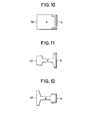
- the molten metal b By subdividing the mold 33 by L-shaped magnetic poles as shown in Figures 8 and 9, the molten metal b, for example, is sealed within a divided-off region. In this state, the molten metal b solidifies inwardly from the wall of the mold 33, forming a solidified shell as indicated by the slanted line in Figure 10.
- the continuous casting proceeds with the molten metal a being positively supplied into the area under this divided-off region so that, advantageously, it is possible to produce a clad cast steel material that exhibits only a very slight mixed region.
- the magnetic poles can instead be disposed vertically (in the shape of an I), with considerably good effect.
- the techniques outlined in the foregoing enable the magnetic force produced by the static magnetic field to effectively prevent mixing of the two types of molten metal. While the effect of the static magnetic field becomes higher in proportion as its strength increases, a practical strength thereof will be in the range of about 2,000 to 8,000 gauss, the actual strength used being determined with consideration to the casting conditions.
- L-shaped magnetic poles are disposed on the exterior of the sides of the mold having greater width.
- the invention is not limited to this arrangement, however, and it is alternatively possible to provide the magnetic poles on the exterior of the sides of the mold having smaller width.
- Molten 18% Cr - 8% Ni stainless steel of the composition indicated at 1 in Table 1 and molten ordinary carbon steel of the composition indicted at Q were retained in separate tundishes and poured through separate nozzles into the upper and lower regions of a strand pool for continuous casting, respectively.
- the thickness of the outer layer was set at 20 mm.
- B 1 m. Therefore, a uniform static magnetic field was applied across the width of the cast metal so as to have its vertical center at 1 m below the meniscus level and to extend vertically over a zone from 10 cm above to 10 cm below this center.
- the magnetic flux density was 5,000 gauss.
- the discharge hole of the immersion nozzle for pouring the molten stainless steel for the outer layer was located about 100 mm below the meniscus level of the molten steel, while the discharge hole of the immersion nozzle for pouring the molten ordinary carbon steel was located immediately beneath the static magnetized field zone.
- a direct-current sta tic magnetic field was applied during the first 10 m of casting, whereafter casting was carried out without application of a static magnetic field. After completion of the casting operation, samples were cut from the strand at typical normal portions thereof, and the sample cross-sections were examined.
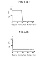
- Figure 4(a) shows the distribution of Cr concentration for a sample (a) produced using a static magnetic field while Figure 4(b) shows the same for a sample (b) produced without use of a static magnetic field.
- the sample (a) had a 20 mm outer layer formed of the stainless steel component and the transition layer between this layer and the inner layer formed of the ordinary carbon steel component was extremely thin.
- the Cr concerntration was high at the surface, it rapidly decreased with increasing depth, showing that the two types of metals mixed within the molten metal pool during casting.
- Molten semi-deoxidized A8 killed steel of the composition indicated at 1 and rimmed steel of the composition indicated at @ in Table 2 were retained in separate tundishes and poured through separate nozzles into the upper and lower regions of a strand pool for continuous casting, respectively.
- the mold measured 250 mm in depth and 1,000 mm in width and the casting speed was 1 m/min.
- the solidification thickness d is obtained from the following equation
- the thickness of the outer layer was set at 20 mm.
- i 1 m. Therefore, a uniform static magnetic field was applied across the width of the cast metal so as to have its vertical center at 1 m below the level of the molten metal surface and to extend vertically over a zone from 10 cm above to 10 cm below this center.
- the magnetic flux density was 3,000 gauss.
- the discharge hole of the immersion nozzle for pouring the molten semi-oxidized Al killed steel for the outer layer was located about 100 mm below-the level of the molten metal surface, while the discharge hole of the immersion nozzle for pouring the molten rimmed steel was located immediately beneath the static magnetized field zone.
- a direct-current static magnetic field was applied during the first 10 m of casting, whereafter casting was carried out without application of a static magnetic field. After completion of the casting operation, samples were cut from the strand at typical normal portions thereof, and the sample cross-sections were examined.
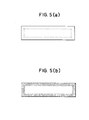
- Figure 5(a) shows the distribution of CO blowholes for a sample (a) produced using a static magnetic field while Figure 5(b) shows the same for a sample (b) produced without use of a static magnetic field.
- the inventors made an investigation to determine the limit of free oxygen (free 0) concentration beyond which CO blowholes form when steel of this composition is used and discovered that needle-shaped CO blowholes form at the surface of the strand when the concentration of free 0 exceed 50 ppm.
- sample (a) shown in Figures 5 (a) a solidified outer layer of steel type (Dextends into the strand to a depth of 20 mm. The free 0 concentration in this layer was 40 ppm and, as a result, absolutely no CO blowholes were formed.
- Molten medium carbon steel of the composition indicated at 1 and molten high carbon steel of the composition indicated at 2 in Table 3 were retained in separate tundishes and poured through separate nozzles into the upper and lower regions of the molten metal pool for continuous casting.
- the mold measured 250 mm in depth and 1,000 mm in width and the casting speed was 1 m/min.
- the solidification thickness d is obtained from the following equation
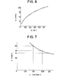
- the distances required for obtaining outer layers with thicknesses of 12 mm, 16 mm and 20 mm were found by the equations (1) - (3) to be (a) 0.36 m, (b) 0.64 m and (c) 1.0 m, respectively.
- a uniform static magnetic field was applied across the width of the cast metal so as to have its vertical center at 0.36 m, 0.64 m and 1.0 m below the level of the molten metal surface and to extend vertically over a zone from 10 cm above to 10 cm below this center.
- the magnetic flux density was 3,000 gauss.
- the discharge hole of the immersioin nozzle for pouring the molten steel of type 1 for the outer layer was located about 100 mm below the level of the molten metal surface, while the discharge hole of the immersion nozzle for pouring the molten steel of the type 1 for the inner layer was located immediately beneath the static magnetized field zone.
- samples were cut from the so-obtained strands (a), (b) and (c) at typical normal portions thereof, and the mean thicknesses of the outer layers were determined. The results are shown in the graph of Figure 6. It was thus demonstrated that by the method of the present invention it is possible in the manner of this Example to control the thickness of the cladding layer of the clad steel material.
- Molten medium carbon steel of the composition indicated at (D and molten high carbon steel of the composition indicated at @ in Table 4 were retained in separate tundishes and poured through separate nozzles into the upper and lower regions of the molten metal pool for continuous casting.
- the uniform magnetic field was applied so as to have its vertical center at 1 m below the level of the molten metal surface and to extend vertically over a zone from 10 cm above to 10 cm below this center.
- the magnetic flux density was 3000 gauss.
- the mold measured 250 mm in depth and 1,000 mm in width and the casting speed was 1 m/min. In the case of 26 this castina speed 1 - 2 m/min. the solidification thickness d is obtained from the followina eauation
- the values of v required for obtaining outer layers with thicknesses of 14 mm, 16 mm and 20 mm were calculated from equation (1) and (4) and found to be (a) 2 m/min, (b) 1.56 m/min and (c) 1 m/min.
- the discharge hole of the immersion nozzle for pouring the molten steel of type 1 for the outer layer was located about 100 mm below the level of the molten metal surface, while the discharge hole of the immersion nozzle for pouring the molten steel of the type @ for the inner layer was located immediately beneath the static magnetized field zone.
- This bloom was rolled to obtain a clad rail which, as illustrated in Figure 11, was constituted predominately of high carbon steel a and had only its base portion formed of the low carbon steel b.
- a high carbon steel (about 0.8 wtO/o C) of the composition ordinarily used as a rail material is used as the molten steel b and a low carbon steel (about 0.3% C) which is a rail material with only its carbon content made low is used as the molten metal a and clad steel bloom is produced using the continuous casting method of this invention, there can be obtained a clad steel rail in which, as shown in Figure 12, only the head of the rail is formed of high carbon steel and the remainder thereof is formed of low carbon steel.
- the method of the present invention uses a static magnetic field to divide the strand pool into separate regions which are supplied with molten metals of different composition, thus minimizing mixing of the metals in the course of continuous casting, whereby it becomes readily possible by continuous casting to produced a composite metal material having a sharply defined boundary between its two layers.
- the magnetic field can be produced to extend vertically through the interior of the continuous casting mold so as to prevent the mixing of molten metals of different compositions poured into the mold on opposite sides thereof, whereby it becomes possible to produce single-sided clad metal strand of various types.
- the method of this invention can also be applied for production of a clad steel rail having its head portion formed of the conventional high carbon steel and the base thereof formed of low carbon steel.
- a clad steel rail having its head portion formed of the conventional high carbon steel and the base thereof formed of low carbon steel.
- Such a rail exhibits extremely high resistance to breakage.
Landscapes
- Engineering & Computer Science (AREA)
- Mechanical Engineering (AREA)
- Continuous Casting (AREA)
Applications Claiming Priority (4)
| Application Number | Priority Date | Filing Date | Title |
|---|---|---|---|
| JP252898/86 | 1986-10-24 | ||
| JP25289886A JPS63108947A (ja) | 1986-10-24 | 1986-10-24 | 複合金属材の連続鋳造方法 |
| JP145159/87 | 1987-06-12 | ||
| JP14515987A JPH07106427B2 (ja) | 1987-06-12 | 1987-06-12 | クラッド鋼鋳片の連続鋳造法 |
Publications (3)
| Publication Number | Publication Date |
|---|---|
| EP0265235A2 true EP0265235A2 (de) | 1988-04-27 |
| EP0265235A3 EP0265235A3 (en) | 1988-08-10 |
| EP0265235B1 EP0265235B1 (de) | 1991-01-09 |
Family
ID=26476365
Family Applications (1)
| Application Number | Title | Priority Date | Filing Date |
|---|---|---|---|
| EP87309281A Expired EP0265235B1 (de) | 1986-10-24 | 1987-10-21 | Stranggiessen von Verbundmetall |
Country Status (4)
| Country | Link |
|---|---|
| US (1) | US4828015A (de) |
| EP (1) | EP0265235B1 (de) |
| CA (1) | CA1296864C (de) |
| DE (1) | DE3767278D1 (de) |
Cited By (3)
| Publication number | Priority date | Publication date | Assignee | Title |
|---|---|---|---|---|
| WO2001066282A1 (fr) * | 2000-03-09 | 2001-09-13 | Kawasaki Steel Corporation | Procede de production pour le coulage continu de billette fondue |
| EP2279813A1 (de) * | 2003-06-24 | 2011-02-02 | Novelis Inc. | Verfahren zum Gießen eines Verbundbarrens |
| EP3871802A4 (de) * | 2018-10-26 | 2021-11-10 | Posco | Giessanlage und giessverfahren |
Families Citing this family (13)
| Publication number | Priority date | Publication date | Assignee | Title |
|---|---|---|---|---|
| EP0587560A4 (de) * | 1991-03-22 | 1994-10-12 | Massachusetts Inst Technology | Verfahren und vorrichtung zur herstellung von mmc mittels elektromagnetischer massenkräfte. |
| US5269366A (en) * | 1991-04-12 | 1993-12-14 | Nippon Steel Corporation | Continuous casting method of multi-layered slab |
| US5755272A (en) * | 1993-12-02 | 1998-05-26 | Massachusetts Institute Of Technology | Method for producing metal matrix composites using electromagnetic body forces |
| CA2678009A1 (en) * | 2007-02-28 | 2008-09-04 | Novelis Inc. | Co-casting of metals by direct-chill casting |
| CN101704075B (zh) * | 2009-11-13 | 2011-12-21 | 江苏大学 | 多元磁场组合熔体反应合成铝基复合材料的方法 |
| CN102069162A (zh) * | 2011-02-24 | 2011-05-25 | 北京科技大学 | 一种包复材料电磁顶出充芯连铸成形设备与工艺方法 |
| US9212072B2 (en) * | 2011-10-13 | 2015-12-15 | Lynell Braught | Apparatus for creating a vortex system |
| KR101890903B1 (ko) | 2014-05-21 | 2018-08-24 | 노벨리스 인크. | 혼합 이덕터 노즐 및 흐름 제어 디바이스 |
| JP6631162B2 (ja) * | 2015-10-30 | 2020-01-15 | 日本製鉄株式会社 | 複層鋳片の連続鋳造方法及び連続鋳造装置 |
| TW202015829A (zh) | 2018-06-08 | 2020-05-01 | 日商日本製鐵股份有限公司 | 複層鑄片之連續鑄造處理的控制方法、裝置及程式 |
| KR102171086B1 (ko) * | 2018-09-28 | 2020-10-28 | 주식회사 포스코 | 주조 모사 장치 및 주조 모사 방법 |
| US12060683B2 (en) | 2020-03-17 | 2024-08-13 | Esab Ab | Electroslag strip cladding |
| CN112296292B (zh) * | 2020-09-11 | 2021-10-01 | 柳州钢铁股份有限公司 | 一种双流板坯连铸的作业方法 |
Family Cites Families (9)
| Publication number | Priority date | Publication date | Assignee | Title |
|---|---|---|---|---|
| US3206808A (en) * | 1962-08-14 | 1965-09-21 | Reynolds Metals Co | Composite-ingot casting system |
| CH450640A (de) * | 1966-09-23 | 1968-01-31 | Concast Ag | Verfahren zur Herstellung von Strängen aus Stahl im Stranggiessverfahren |
| JPS4944859A (de) * | 1972-07-18 | 1974-04-27 | ||
| US3985179A (en) * | 1975-07-28 | 1976-10-21 | Kaiser Aluminum & Chemical Corporation | Electromagnetic casting apparatus |
| JPS6054821B2 (ja) * | 1980-10-29 | 1985-12-02 | 日本鋼管株式会社 | 複合鋳片の水平連続鋳造法 |
| JPS57190761A (en) * | 1981-05-18 | 1982-11-24 | Yoshida Dental Mfg Co Ltd | Centrifugal casting machine |
| JPS59101261A (ja) * | 1982-12-02 | 1984-06-11 | Kawasaki Steel Corp | 静磁場溶鋼流制動を行う連続鋳造方法 |
| US4567936A (en) * | 1984-08-20 | 1986-02-04 | Kaiser Aluminum & Chemical Corporation | Composite ingot casting |
| JPS61193755A (ja) * | 1985-02-25 | 1986-08-28 | Toshiba Corp | 電磁撹拌方法 |
-
1987
- 1987-10-09 US US07/107,471 patent/US4828015A/en not_active Expired - Lifetime
- 1987-10-20 CA CA000549701A patent/CA1296864C/en not_active Expired - Lifetime
- 1987-10-21 EP EP87309281A patent/EP0265235B1/de not_active Expired
- 1987-10-21 DE DE8787309281T patent/DE3767278D1/de not_active Expired - Lifetime
Cited By (8)
| Publication number | Priority date | Publication date | Assignee | Title |
|---|---|---|---|---|
| WO2001066282A1 (fr) * | 2000-03-09 | 2001-09-13 | Kawasaki Steel Corporation | Procede de production pour le coulage continu de billette fondue |
| US6557623B2 (en) | 2000-03-09 | 2003-05-06 | Kawasaki Steel Corporation | Production method for continuous casting cast billet |
| EP2279813A1 (de) * | 2003-06-24 | 2011-02-02 | Novelis Inc. | Verfahren zum Gießen eines Verbundbarrens |
| EP2279814A1 (de) * | 2003-06-24 | 2011-02-02 | Novelis Inc. | Verfahren zum Gießen eines Verbundbarrens |
| US8312915B2 (en) | 2003-06-24 | 2012-11-20 | Novelis Inc. | Method for casting composite ingot |
| US8415025B2 (en) | 2003-06-24 | 2013-04-09 | Novelis Inc. | Composite metal as cast ingot |
| US8927113B2 (en) | 2003-06-24 | 2015-01-06 | Novelis Inc. | Composite metal ingot |
| EP3871802A4 (de) * | 2018-10-26 | 2021-11-10 | Posco | Giessanlage und giessverfahren |
Also Published As
| Publication number | Publication date |
|---|---|
| DE3767278D1 (de) | 1991-02-14 |
| EP0265235B1 (de) | 1991-01-09 |
| CA1296864C (en) | 1992-03-10 |
| US4828015A (en) | 1989-05-09 |
| EP0265235A3 (en) | 1988-08-10 |
Similar Documents
| Publication | Publication Date | Title |
|---|---|---|
| EP0265235A2 (de) | Stranggiessen von Verbundmetall | |
| RU2297900C2 (ru) | Способ изготовления стальной полосы и тонкая стальная полоса, полученная этим способом | |
| EP0685280A1 (de) | Verfahren zum kontinuierlichen Giessen von Stahl mit hohem Kohlenstoffgehalt | |
| EP3369495A1 (de) | Kontinuierliche herstellungsvorrichtung und kontinuierliches herstellungsverfahren für mehrschichtige platte | |
| EP0596134A1 (de) | Verfahren zum herstellen eines doppellagigen giessstücke | |
| EP1195211B1 (de) | Herstellungsverfahren für stranggussknüppel | |
| EP0523837B1 (de) | Stranggiessen von Stahl | |
| EP1350585B1 (de) | Vorrichtung zum Stranggiessen mit Badbewegung | |
| CA1036471A (en) | Method of continuously casting steel | |
| CA2084986C (en) | Continuous casting method of multi-layered slab | |
| JP3099157B2 (ja) | 連続鋳造方法 | |
| JP2790781B2 (ja) | 広幅薄鋳片の連続鋳造装置用注入ノズル | |
| JP2661797B2 (ja) | 複層鋳片鋳造方法 | |
| JPH10113752A (ja) | アモルファス合金製造のための溶融合金供給方法および供給用ロングノズル | |
| JPS61266155A (ja) | クラツド鋳片の連続鋳造方法及びその装置 | |
| CA1152723A (en) | Process for continuous casting of a slightly deoxidized steel slab | |
| SU933196A1 (ru) | Способ непрерывной разливки металла | |
| JPWO1993022085A1 (ja) | 複層鋳片鋳造方法 | |
| JP2898199B2 (ja) | 連鋳鋳片の製造方法 | |
| JPS62130752A (ja) | ブル−ムもしくはビレツトの連続鋳造方法 | |
| JPH01271031A (ja) | 複層鋳片の連続鋳造方法 | |
| JPH08187557A (ja) | 電磁場を用いた鋼の連続鋳造方法 | |
| JP2845706B2 (ja) | 連続鋳造設備のモールド装置 | |
| JP3395749B2 (ja) | 鋼の連続鋳造方法 | |
| EP0034469A1 (de) | Gefüllter rohrförmiger Gegenstand und Verfahren zum Giessen eines mit Bor behandelten Stahles |
Legal Events
| Date | Code | Title | Description |
|---|---|---|---|
| PUAI | Public reference made under article 153(3) epc to a published international application that has entered the european phase |
Free format text: ORIGINAL CODE: 0009012 |
|
| AK | Designated contracting states |
Kind code of ref document: A2 Designated state(s): DE FR GB IT |
|
| PUAL | Search report despatched |
Free format text: ORIGINAL CODE: 0009013 |
|
| AK | Designated contracting states |
Kind code of ref document: A3 Designated state(s): DE FR GB IT |
|
| 17P | Request for examination filed |
Effective date: 19881024 |
|
| 17Q | First examination report despatched |
Effective date: 19890306 |
|
| GRAA | (expected) grant |
Free format text: ORIGINAL CODE: 0009210 |
|
| AK | Designated contracting states |
Kind code of ref document: B1 Designated state(s): DE FR GB IT |
|
| REF | Corresponds to: |
Ref document number: 3767278 Country of ref document: DE Date of ref document: 19910214 |
|
| ITF | It: translation for a ep patent filed | ||
| ET | Fr: translation filed | ||
| PLBE | No opposition filed within time limit |
Free format text: ORIGINAL CODE: 0009261 |
|
| STAA | Information on the status of an ep patent application or granted ep patent |
Free format text: STATUS: NO OPPOSITION FILED WITHIN TIME LIMIT |
|
| 26N | No opposition filed | ||
| REG | Reference to a national code |
Ref country code: GB Ref legal event code: IF02 |
|
| PGFP | Annual fee paid to national office [announced via postgrant information from national office to epo] |
Ref country code: FR Payment date: 20021008 Year of fee payment: 16 |
|
| PGFP | Annual fee paid to national office [announced via postgrant information from national office to epo] |
Ref country code: GB Payment date: 20021016 Year of fee payment: 16 |
|
| PGFP | Annual fee paid to national office [announced via postgrant information from national office to epo] |
Ref country code: DE Payment date: 20021024 Year of fee payment: 16 |
|
| PG25 | Lapsed in a contracting state [announced via postgrant information from national office to epo] |
Ref country code: GB Free format text: LAPSE BECAUSE OF NON-PAYMENT OF DUE FEES Effective date: 20031021 |
|
| PG25 | Lapsed in a contracting state [announced via postgrant information from national office to epo] |
Ref country code: DE Free format text: LAPSE BECAUSE OF NON-PAYMENT OF DUE FEES Effective date: 20040501 |
|
| GBPC | Gb: european patent ceased through non-payment of renewal fee |
Effective date: 20031021 |
|
| PG25 | Lapsed in a contracting state [announced via postgrant information from national office to epo] |
Ref country code: FR Free format text: LAPSE BECAUSE OF NON-PAYMENT OF DUE FEES Effective date: 20040630 |
|
| REG | Reference to a national code |
Ref country code: FR Ref legal event code: ST |
|
| PG25 | Lapsed in a contracting state [announced via postgrant information from national office to epo] |
Ref country code: IT Free format text: LAPSE BECAUSE OF NON-PAYMENT OF DUE FEES;WARNING: LAPSES OF ITALIAN PATENTS WITH EFFECTIVE DATE BEFORE 2007 MAY HAVE OCCURRED AT ANY TIME BEFORE 2007. THE CORRECT EFFECTIVE DATE MAY BE DIFFERENT FROM THE ONE RECORDED. Effective date: 20051021 |