EP0264758A1 - Wellenmessgerät - Google Patents
Wellenmessgerät Download PDFInfo
- Publication number
- EP0264758A1 EP0264758A1 EP87114852A EP87114852A EP0264758A1 EP 0264758 A1 EP0264758 A1 EP 0264758A1 EP 87114852 A EP87114852 A EP 87114852A EP 87114852 A EP87114852 A EP 87114852A EP 0264758 A1 EP0264758 A1 EP 0264758A1
- Authority
- EP
- European Patent Office
- Prior art keywords
- axis
- button
- button holder
- rotation
- holder
- Prior art date
- Legal status (The legal status is an assumption and is not a legal conclusion. Google has not performed a legal analysis and makes no representation as to the accuracy of the status listed.)
- Withdrawn
Links
Images
Classifications
-
- G—PHYSICS
- G01—MEASURING; TESTING
- G01B—MEASURING LENGTH, THICKNESS OR SIMILAR LINEAR DIMENSIONS; MEASURING ANGLES; MEASURING AREAS; MEASURING IRREGULARITIES OF SURFACES OR CONTOURS
- G01B5/00—Measuring arrangements characterised by the use of mechanical techniques
- G01B5/0002—Arrangements for supporting, fixing or guiding the measuring instrument or the object to be measured
-
- G—PHYSICS
- G01—MEASURING; TESTING
- G01B—MEASURING LENGTH, THICKNESS OR SIMILAR LINEAR DIMENSIONS; MEASURING ANGLES; MEASURING AREAS; MEASURING IRREGULARITIES OF SURFACES OR CONTOURS
- G01B5/00—Measuring arrangements characterised by the use of mechanical techniques
- G01B5/20—Measuring arrangements characterised by the use of mechanical techniques for measuring contours or curvatures
- G01B5/207—Measuring arrangements characterised by the use of mechanical techniques for measuring contours or curvatures using a plurality of fixed, simultaneously operating transducers
Definitions
- the invention relates to a measuring device for determining the dimensional accuracy of radial surfaces running transversely to an axis on a shaped body, with bearing arrangements provided on a base frame, lying opposite one another and in alignment with one another, which define an axis for the shaped body, and with at least one transverse to this axis movable button holder to which at least one sensor sensing a radial surface can be attached.
- “Shaped bodies” are to be understood as bodies produced in any way; however, a particularly preferred field of application of the invention is the measurement of rotating bodies.
- Measuring devices of this type are used to shape waves u. Check the rotating body for dimensional accuracy. The rotating body to be tested is then in the bearing arrangements, mostly bearing tips, are inserted and then at least one button (generally several) is placed on the surfaces to be checked. Each button is connected to a load cell, which shows the fine deflections of the button on the respective surface during the rotation of the rotating body or the shaft on a display instrument.
- the invention is therefore based on the object of designing a measuring device of the type mentioned at the outset in such a way that it is easier to handle and the risk of damage to the respective button or of changing its setting position is avoided.
- buttons holder is parallel to the axis in the direction.
- a plurality of buttons attached to a button holder can also be axially displaced at the same time. This may initially be done by hand, whereupon the push button holder is brought to the rotating body and the push button holder is manually pushed back into its starting position parallel to the axis of rotation in such a way that the push button or push buttons contact the associated radial surface of the rotating body. However, it is more favorable if an axial movement drive is provided for this movement.
- the axial movement of the stylus holder could be coupled with the movement of the stylus holder towards the rotating body by a corresponding gear connection in such a way that the movement of the stylus holder towards the rotating body takes place (in the radial direction) and only then through a movement parallel to the axis of rotation (axial movement)
- the buttons are placed on the radial surfaces.
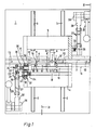
- a guide slot 2 which is T-shaped in reverse cross section.
- a pair of guide rails 3 run in the vertical direction to this guide slot 2 on both sides of the same.
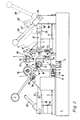
- a holding bracket 4 or 5 is slidably guided, as can be seen particularly clearly from FIG. 2, in which an initial position 5 ' of the bracket 5 shown in dashed lines i st.
- the guide slot 2 is used for the central attachment of various parts.
- a spacer 6 may be inserted and fixed by means of a clamping screw 7, with the aid of which the end position of the two support brackets 4, 5 can be determined at a distance from the center defined by the guide slot 2.
- the spacer 6 is provided on both sides with end stops 8 which can be adjusted by means of screws 10 (FIG. 2) and which cooperate with corresponding counter stops 9 on the support brackets 4, 5 (only the counter stop 9 of the support bracket 4 is shown in FIG. 2).
- the construction of the two support brackets 4, 5 is mirror-symmetrical.
- Bearing blocks 11, each with a rotatable bearing tip 12, can be inserted into the guide slot 2 from both sides and can be fixed by means of at least one screw 13 (indicated by dash-dotted lines in FIG. 1).
- a rotating body 14 to be tested (dash-dot-dotted in FIG. 1) can be rotatably supported around an axis of rotation A.
- the rotating body 14 is offset several times and each has radial shoulder surfaces r, R and R und, the dimensional accuracy of which is to be checked in the axial direction.
- buttons 16, 16 ' which can be pivoted elastically about an axis 15 and which lie against these radial surfaces r, R and their deflection about the axis 15 in a known manner on a display instrument 17 (FIG. 2) or on a Data processing system is transmitted.
- buttons 16, 16 ⁇ it is somewhat difficult to lift the buttons 16, 16 ⁇ by hand in such a way that they reach their associated radial surface r or R.
- One way out could be to attach the buttons 16, 16 ⁇ to their button holder 18 or 19 only when this is already in the end position shown in FIG. 1, but the space is then so limited that this is not possible can only be accomplished with great effort.
- buttons 16, 16 ⁇ on their associated radial surface R or r for which purpose the button holders 18, 19 can be displaced in the direction of their longitudinal axis, and thus parallel to the axis of rotation A, on the respective mounting bracket 4 or 5 are stored.
- the button holder 18 leading the button 16 (refer to FIG. 1) during the movement of the support bracket 4 could be moved so far to the left that the button 16 will surely pass the peripheral surface U, whereas the button 16aster on its button holder 19 would be shifted to the right.
- the button holders 18, 19 could then each be displaced such that the buttons 16, 16 ⁇ come into contact with the associated radial surfaces R, r.
- an embodiment for handling is provided.
- the ends of the button holders 18, 19 have inclined surfaces 21, 22 which are arranged in mirror image fashion with respect to an axis of symmetry.
- two projecting pins 23, 24 cooperate, which protrude from a lever 26 which can be pivoted about an axis 25 (cf. FIGS. 1, 2).
- a lever 27 connects the lever 26 to an arm 28, which is connected to an actuating lever 29 and is pivotably mounted with the latter on a bearing piece 30.
- the actuating lever 29 takes the position 29, the arm 28 and the position 28 (indicated by dashed lines in FIG. 2).
- the link 27 on the left in FIG. 2 pushes the bracket 4 against the stop 8.
- the arm 28 is then in a position 28 in (right in Fig. 2).
- the buttons 16, 16 ⁇ each pass the circumferential surface of the rotating body 14 in the area of the associated radial surfaces R, r. If the actuating lever 29 is now pressed further, then the arm 28 and the handlebar 27 stretch against the force of the spring 33 into their end position (shown in the drawing with solid lines) and thereby pivot the lever 26.
- the invention is of course not limited to the measurement of rotating bodies or of radial surfaces along axes of rotation, but that any shaped bodies can also advantageously be measured in the rest position.
- the exemplary embodiment described can still be modified in a manner that is easy to imagine with the aid of the drawing, in that the inclined surfaces 21g 22 - with reference to FIG. 1 - are not turned upwards but downwards, the associated pin 23 or 24 correspondingly below the associated button holder 18 or 19 would be shown.
- a pivoting of the actuating lever 29 from its position 29 ⁇ (Fig. 2) clockwise would cause the pins 23, 24 to lie against the inclined surfaces 21, 22 and move them in the sense of the evasive movement described for the buttons 16, 16 ⁇ .
- the inclined surface 21 is arranged on a groove, the pin 23 on the base of the groove would exert pressure on the support bracket in the direction Exercise to its end position and therefore move the bracket 4 or 5 against the same.
- the actuating lever 29 may be connected to a shaft 36 which extends to the other side of the associated holding bracket and which may then be mounted on the opposite side in a further bearing piece which corresponds to the bearing piece 30.
- a handlebar 27 can then be provided on both sides of each support bracket, with the lever 26 also being able to be arranged on each side, so that a lever 26 holds the button carrier 18 from one side and the other lever 26 the button holder 19 actuated from the other side via an inclined surface.
- This may have the advantage that the inclined surface n on both button holders 18, 19 can be of the same design, therefore the two button holders are of identical design and the number of different parts is thus reduced.
- the compression spring 33 would be compressed during this movement. With the release of the actuating lever 29, the compression spring 33 would come into effect in such a case that the pin 23 is pressed out of the groove on the inclined surface 21, so that the return springs 34, 35 can relax and the buttons 16, 16 ⁇ on them Create radial surfaces.
- the movable front end i.e. the button 16
- carrying head 18 ' is itself a part of the button holder 18 due to its fixation on the button holder 18.
- the head 18 ⁇ could be movable and deflectable relative to a stationary pushbutton holder 18 (which is then only part of the support bracket 4), for example in that its clamping bracket 20 (FIG. 2) has a pivot axis about which the head 18 ⁇ in the direction of the respective radial surface R can be pivoted towards or away from it.
Landscapes
- Physics & Mathematics (AREA)
- General Physics & Mathematics (AREA)
- A Measuring Device Byusing Mechanical Method (AREA)
- Length Measuring Devices With Unspecified Measuring Means (AREA)
Applications Claiming Priority (2)
| Application Number | Priority Date | Filing Date | Title |
|---|---|---|---|
| CH4083/86 | 1986-10-13 | ||
| CH408386A CH671098A5 (enExample) | 1986-10-13 | 1986-10-13 |
Publications (1)
| Publication Number | Publication Date |
|---|---|
| EP0264758A1 true EP0264758A1 (de) | 1988-04-27 |
Family
ID=4269507
Family Applications (1)
| Application Number | Title | Priority Date | Filing Date |
|---|---|---|---|
| EP87114852A Withdrawn EP0264758A1 (de) | 1986-10-13 | 1987-10-12 | Wellenmessgerät |
Country Status (3)
| Country | Link |
|---|---|
| EP (1) | EP0264758A1 (enExample) |
| JP (1) | JPS63165709A (enExample) |
| CH (1) | CH671098A5 (enExample) |
Cited By (1)
| Publication number | Priority date | Publication date | Assignee | Title |
|---|---|---|---|---|
| CN110375627A (zh) * | 2019-08-26 | 2019-10-25 | 付国军 | 一种平面度检测设备 |
Citations (3)
| Publication number | Priority date | Publication date | Assignee | Title |
|---|---|---|---|---|
| DE488049C (de) * | 1927-04-09 | 1929-12-19 | Henschel & Sohn Akt Ges | Pruefstand fuer Lokomotivradsaetze |
| US3905116A (en) * | 1973-10-15 | 1975-09-16 | Allis Chalmers | Crankshaft bearing measuring apparatus |
| CH576120A5 (enExample) * | 1973-10-30 | 1976-05-31 | Carl Mahr Fa |
-
1986
- 1986-10-13 CH CH408386A patent/CH671098A5/de not_active IP Right Cessation
-
1987
- 1987-10-12 EP EP87114852A patent/EP0264758A1/de not_active Withdrawn
- 1987-10-13 JP JP25646287A patent/JPS63165709A/ja active Pending
Patent Citations (3)
| Publication number | Priority date | Publication date | Assignee | Title |
|---|---|---|---|---|
| DE488049C (de) * | 1927-04-09 | 1929-12-19 | Henschel & Sohn Akt Ges | Pruefstand fuer Lokomotivradsaetze |
| US3905116A (en) * | 1973-10-15 | 1975-09-16 | Allis Chalmers | Crankshaft bearing measuring apparatus |
| CH576120A5 (enExample) * | 1973-10-30 | 1976-05-31 | Carl Mahr Fa |
Cited By (2)
| Publication number | Priority date | Publication date | Assignee | Title |
|---|---|---|---|---|
| CN110375627A (zh) * | 2019-08-26 | 2019-10-25 | 付国军 | 一种平面度检测设备 |
| CN110375627B (zh) * | 2019-08-26 | 2020-12-11 | 无锡杰尔维科技有限公司 | 一种平面度检测设备 |
Also Published As
| Publication number | Publication date |
|---|---|
| CH671098A5 (enExample) | 1989-07-31 |
| JPS63165709A (ja) | 1988-07-09 |
Similar Documents
| Publication | Publication Date | Title |
|---|---|---|
| DE3131673C2 (de) | Digitales elektrisches Längenmeßgerät | |
| EP0204100B1 (de) | Haltevorrichtung | |
| DE2611476C2 (de) | Profilindikator | |
| DE102020216084A1 (de) | Materialprüfvorrichtung für Biegeversuche und Verfahren zum Durchführen eines Biegeversuchs | |
| DE3229664C2 (enExample) | ||
| DE1623274B2 (de) | Anreiß , Meß oder Markierungs einrichtung | |
| DE102009036247A1 (de) | Vorrichtung zur Durchführung von Bauteil- und Werkstoffprüfungen an Proben | |
| DE723652C (de) | Geraet zum Feststellen der Oberflaechenbeschaffenheit von Koerpern | |
| DE1447355A1 (de) | Vorrichtung zur schrittweisen Verstellung eines Schlittens | |
| DE3819980C2 (de) | Vorrichtung zur Prüfung der Biegesteifigkeit oder -festigkeit bzw. der elastischen Rückfederung von Stabmaterial | |
| DE2237396C2 (de) | Ellipsen-Zeichengerät | |
| EP0264758A1 (de) | Wellenmessgerät | |
| DE2931639C2 (de) | Vorrichtung zum Anbringen eines Begrenzungsteils mit zwei gespreizten Schenkeln an einem Längsrad eines Reißverschlußtragbandes | |
| DE2260614B2 (de) | Härteprüfmaschine nach dem Vorlastverfahren nach Rockwell | |
| DE2720673A1 (de) | Vorrichtung zum spannen des gummituches auf einem zylinder einer offsetdruckmaschine | |
| DE3719592A1 (de) | Spannvorrichtung | |
| CH683638A5 (de) | Längenmessgerät. | |
| DE1573470C3 (de) | Vorrichtung für Biegeversuche | |
| EP2264392A2 (de) | Pfeiltester | |
| DE3045416A1 (de) | Hoehenmessinstrument | |
| DE2606888A1 (de) | Geraet zum pruefen von schraubenfedern | |
| DE1573430C (de) | Härteprüfer | |
| DE29712452U1 (de) | Gerät zum Prüfen und Messen von Innengewinden | |
| DE824458C (de) | Zeicheneinrichtung | |
| DE3206212A1 (de) | Spannkopf eines blechstreckers mit einer zentriervorrichtung |
Legal Events
| Date | Code | Title | Description |
|---|---|---|---|
| PUAI | Public reference made under article 153(3) epc to a published international application that has entered the european phase |
Free format text: ORIGINAL CODE: 0009012 |
|
| AK | Designated contracting states |
Kind code of ref document: A1 Designated state(s): AT BE DE ES FR GB GR IT LU NL SE |
|
| STAA | Information on the status of an ep patent application or granted ep patent |
Free format text: STATUS: THE APPLICATION IS DEEMED TO BE WITHDRAWN |
|
| 18D | Application deemed to be withdrawn |
Effective date: 19881021 |
|
| RIN1 | Information on inventor provided before grant (corrected) |
Inventor name: BOETTCHER, WOLFGANG, |