EP0264584A2 - Elément d'impression - Google Patents
Elément d'impression Download PDFInfo
- Publication number
- EP0264584A2 EP0264584A2 EP87112468A EP87112468A EP0264584A2 EP 0264584 A2 EP0264584 A2 EP 0264584A2 EP 87112468 A EP87112468 A EP 87112468A EP 87112468 A EP87112468 A EP 87112468A EP 0264584 A2 EP0264584 A2 EP 0264584A2
- Authority
- EP
- European Patent Office
- Prior art keywords
- printing unit
- actuating button
- locking
- unit according
- carrier
- Prior art date
- Legal status (The legal status is an assumption and is not a legal conclusion. Google has not performed a legal analysis and makes no representation as to the accuracy of the status listed.)
- Granted
Links
- 239000000969 carrier Substances 0.000 claims abstract description 19
- 230000002093 peripheral effect Effects 0.000 claims abstract description 5
- 239000011324 bead Substances 0.000 claims description 10
- 238000006073 displacement reaction Methods 0.000 claims 2
- 230000003993 interaction Effects 0.000 description 5
- 230000000694 effects Effects 0.000 description 4
- 230000004323 axial length Effects 0.000 description 3
- 239000000463 material Substances 0.000 description 3
- 230000006978 adaptation Effects 0.000 description 2
- 230000008719 thickening Effects 0.000 description 2
- 230000001627 detrimental effect Effects 0.000 description 1
- 238000011161 development Methods 0.000 description 1
- 230000018109 developmental process Effects 0.000 description 1
- 238000002372 labelling Methods 0.000 description 1
Images


Classifications
-
- B—PERFORMING OPERATIONS; TRANSPORTING
- B41—PRINTING; LINING MACHINES; TYPEWRITERS; STAMPS
- B41K—STAMPS; STAMPING OR NUMBERING APPARATUS OR DEVICES
- B41K1/00—Portable hand-operated devices without means for supporting or locating the articles to be stamped, i.e. hand stamps; Inking devices or other accessories therefor
- B41K1/08—Portable hand-operated devices without means for supporting or locating the articles to be stamped, i.e. hand stamps; Inking devices or other accessories therefor with a flat stamping surface and changeable characters
- B41K1/10—Portable hand-operated devices without means for supporting or locating the articles to be stamped, i.e. hand stamps; Inking devices or other accessories therefor with a flat stamping surface and changeable characters having movable type-carrying bands or chains
Definitions
- the invention relates to a printing unit with a plurality of type carriers, which have printing types on their outer circumferential surface in one area and reading types in another area, the printing types being able to be brought into a printing position by rotating the type carriers, and an adjusting arrangement containing an actuating button, which is moved axially each of the type carriers can be brought into a drive connection for rotating them and stop means for limiting the torsion path of the type carriers.
- Such a printing unit is known from DE-PS 34 06 762.
- the sling means prevent the type carriers from turning as far as possible by turning the adjusting knob and the adjusting shaft connected to it be rotated so that the reading types reach the printing position and come into contact with the printing ink in this position. This would seriously impair the readability of the reading types.
- a slip clutch is provided in the known printing unit between an adjusting shaft and an actuating button seated on it, which slips and prevents further rotation of the adjusting shaft and the type carrier coupled therewith as soon as the torque transmitted from the actuating button to the adjusting shaft is greater than the torque required to turn the type carrier becomes.
- the limit torque at which the slipping clutch begins to slip is predetermined by the interaction of the material of the actuation button and the fit with which the actuation button sits on the adjusting shaft. It has been shown that the exact observance of the limit torque leads to difficulties, since it requires a great constancy of the material properties of the actuating button. Factors over which the printing group manufacturer has no influence can influence the limit torque; for example, the limit torque is drastically reduced when oil gets on the adjusting shaft. In this case it can be reduced, for example, to such an extent that normal adjustment of the type carrier is no longer possible, since the actuating button slips on the adjusting shaft when this adjusting torque is applied.
- Another problem with the known printing unit is that it cannot be adapted to different operating conditions, that is to say to different required limiting torques. In practice, however, the torques required for the adjustment of the type carriers are different, so that accordingly different limit torques should also be set.
- the type carriers are belts which are guided around setting wheels and a fixed deflection edge
- belts of different widths also require adjusting torques of different sizes. This results from the fact that the belts can be guided around the deflection edge with narrow belts with a lower torque than with wide belts. If only a single limit torque can be set, this torque must be set to a value that is greater than the largest torque required to adjust the type carrier. This value can, however, be so great that damage to the printing unit occurs even before the limit torque is exceeded, because the desired slipping does not yet occur if the operator tries to turn the actuating button anyway after the slings become effective.
- the invention has for its object to provide a printing unit, in which the limit torque which can be transmitted to the type carrier via the drive connection and which is exceeded when the drive connection is interrupted can be set according to the respective requirements.
- resilient locking elements which hold the actuating button with a locking torque determined by its spring hardness, which is greater than the torque required for rotating the type support, against rotation relative to the type support connected to the adjusting arrangement, and with the locking elements which can be brought into engagement to influence the spring hardness of the locking elements.
- the limit torque is determined by the interaction of the locking elements with the adjusting element.
- the locking elements generate a certain locking torque due to their spring hardness, which can then be influenced by means of the adjusting element in order to achieve the desired limit torque.
- different setting elements which accordingly also influence the spring hardness of the locking elements differently, different limit torques can be set, which enables the desired adaptability of the printing unit to different applications with different type carrier sets.
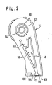
- the printing unit 10 shown in FIG. 1 is a stamp printing unit in which type tapes 12 are used as type carriers.
- the printing unit contains two housing halves 14 and 16 which can be connected to one another via snap hooks 18.
- an adjusting shaft 20 is rotatably mounted, over which a slotted sleeve 22 is pushed.
- Carriers 24 attached to the end of the adjusting shaft 20 engage through slots 26 in the sleeve 22 beyond their outer circumference.
- Adjusting wheels 34 are seated on the sleeve 22, which have grooves 36 on their inner circumferential surface surrounding a central opening 35, into which the drivers 24 of the setting shaft 20 engage.
- the setting wheels 34 are also provided on their outer circumferential surface with grooves 38, into which projections 40 attached to the inner circumferential surface of the type strips 12 engage. In this way, the type bands 12 can be moved via the engagement between the drivers 24 and the grooves 36 and the engagement between the grooves 38 and the projections 40.
- the type tapes 12 are placed around the setting wheels 34 in the printing unit, and they also encompass a pressure web 42 located on the lower end face of the housing half 14, which serves as a deflecting edge for the type tapes 12.
- the type of printing that occurs at the respective one position of the type tapes 12 just below the web 42, each produces the desired impression.
- the reading types are shown on the type tapes 12 in FIG. 1; the print types are located on the rear side of the type support set formed by the type supports 12, which cannot be seen in FIG. 1.
- the recognizable reading types 44 and the respectively assigned printing types are attached to the type tapes 12 in such a way that whenever a printing type is below the printing web 42 in the printing position, the corresponding reading type is visible through a window 46 in the window carrier 30. In this way, it can always be seen through the window 46 which print types are currently in the printing position under the printing web 42.
- the pressure web 42 is attached in one piece to the lower end of a carrier element 48 connected to the housing half 14.
- the carrier element 48 has a recess 50 in which, when the printing unit is assembled, there is a rubber strip 52 and a coil spring 54 above it.
- the rubber strip 52 and the coil spring 54 together have such a height that the coil spring 54 protrudes upward from the recess 50 and comes into contact with the setting wheels 34 arranged above it.
- the coil spring 54 exerts a limited holding force on the setting wheels, which counteracts their rotation.
- the stamp printing unit can be screwed, for example, to a printing unit carrier of a hand-held labeling device.
- the corresponding screws can be inserted through holes in the housing halves 14, 16 and screwed into threaded holes in the ends of the square piece 56.
- annular collars 60, 62 are provided, the radial distance between which forms a recess 64, the radial dimension of which is equal to the wall thickness of the sleeve 22, so that this sleeve is pushed into the recess and separated from the annular collars 60 and 62 can be held.
- the inner collar 62 engages inside the sleeve 22, while the outer collar 60 surrounds the sleeve 22 on the outside.
- the two ring collars have only a small axial extent, so that they each hold only the rightmost end of the sleeve 22 in FIG. 1.
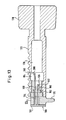
- the setting shaft of the printing unit of Fig. 1 is shown in an enlarged view.
- the end region 28 of the setting shaft 20 intended for receiving the actuating button 32 has a partially square cross section with rounded corners, so that four locking surfaces 66 are created.
- the setting shaft 20 has a bead 68 and an adjoining circumferential groove 70.
- a diametrical slot 72 provided in the end region 28 of the setting shaft 20 produces a certain elasticity of this end region and a resilience of the bead 68.
- the bead 68 and the circumferential groove 70 have the purpose of securely holding the actuating button 32 pushed onto the end region 28 without the latter being included Help must be attached to additional resources. How the detention is carried out will then be discussed can still be seen in the description of the design of the actuating button.
- the end region 28 of the setting shaft 20 projects through an opening 74 in a side plate 76 of the window support 30, the step 78 acting on the setting shaft 20 as a stop which prevents the setting shaft 20 from being pushed further into the opening 74.
- the section of the end region 28, which has the square cross section, projects out of the opening 74 in the side plate 76 to the left in the view of FIG. 1, so that the actuating button 32 can be pushed onto the end region.
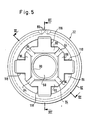
- the operating button 32 is slightly conical on its outer circumferential surface, so that it is easier to touch and operate.
- the outer circumferential surface is corrugated, which is indicated in FIG. 5 to simplify the illustration only with the aid of two corrugated grooves 80.
- the actuation button 32 has an outer sleeve 82 and an inner sleeve 84 which is connected to the outer sleeve 82 on the end face of the actuation button 32.
- the inner sleeve 84 surrounds an inner cavity 88 which has a constriction in the form of an annular bead 90 in the region of the end face 84.
- the annular bead 90 presses the bead 68 together, taking advantage of the flexibility given by the slot 72, until the annular bead 90 slides into the circumferential groove 70.
- the bead 68 then comes to rest in the extension 92 in the actuation button 32, so that the actuation button 32 is securely held on the setting shaft 20.
- the inner sleeve 84 of the actuating button 32 has an essentially square cross section, as can be seen in FIG. 5. At the corners of the square shape, slots 94 are provided in the axial direction, so that four axially extending locking fingers 96 are formed which, when the actuating button 32 is pushed onto the end region 28 of the setting shaft 20, rest against the locking surfaces 66. If the rotation of the setting shaft 20 is not counteracted by a section modulus, the setting shaft 20 can be rotated by means of the pushed-on actuation button 32 due to the interaction of the locking fingers 96 with the locking surfaces 66. The locking fingers 96 can be deflected in the radial direction due to the presence of the slots 94 and act like springs which have a certain spring hardness. This spring hardness is determined by the material and the structural design of the locking fingers.
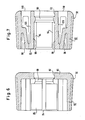
- Fig. 7 shows that the free ends of the locking fingers 96 are connected to the outer sleeve via connecting webs 98, the location at which the connecting webs are connected to the outer sleeve 82 being approximately in the middle of the longitudinal extension of the outer sleeve 82.
- These connecting webs increase the spring hardness of the latching fingers, but otherwise have no influence on the latching fingers 96, which act like leaf springs clamped on one side.
- the printing unit of FIG. 1 is designed in such a way that the type tapes 12 can only execute a predetermined adjustment path when the adjusting shaft 20 is rotated, a very large section modulus being opposed to each further rotation.
- This Large section modulus is generated by 12 projections 100 and 102 are attached to the inner circumferential surface of the type tapes, which are dimensioned so that they are not a gap 106 between the pressure web 42 and the wall of the housing 14 or a gap between the pressure web 42 and fit through a stop web 108 connected to the housing 14.
- the two projections 100 and 102 thus limit the adjustment path of the type straps in both adjustment directions in such a way that, although all types of print can get under the web 42, but not the reading types 44 assigned to the type of printing. So if a type type has been adjusted so far that If the projection 100 comes into contact with the upper edge 110 of the pressure web 142, the section modulus which counteracts the further rotation increases very sharply.
- the spring hardness of the locking fingers 96 is dimensioned such that in this situation the spring fingers 96 are deflected radially outward, so that the locking force exerted by the locking fingers 96 is overcome and the actuating button 32 slips on the end region 28 of the adjusting shaft 20. In this way it is prevented that any further damage to the printing unit is caused by a violent turning of the operating button 32.
- the projection 102 leads to a sharp increase in the section modulus.
- the limit torque at which the slipping of the actuating button 37 on the end section 28 of the adjusting shaft 20 must be adapted to the respective circumstances.
- this is to be used for adjustment Torque relatively low, since the type tapes can be pulled around the pressure web 42 with relatively little force.
- the limit torque must have a higher value.
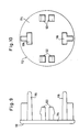
- an adjusting element 112 is provided, which is explained with reference to FIGS. 8, 9 and 10.
- the adjusting member 112 has a circular disk 114 which rigidly connects a plurality of fastening elements 116 to one another. These stiffening elements 116 protrude vertically from the disk 114, and they can be inserted into openings 118 in the end wall 86 of the actuating button 32. As shown in FIG. 8, the stiffening elements 116 rest against the rear surfaces 120 of the locking fingers 96 in the pushed-in state and thereby increase the spring hardness of these locking fingers 96.
- the disk 114 of the adjusting member 112 lies against the end wall 86 of the actuating button 32.
- two stiffening elements 116 are attached to the disk 114, which can be brought into engagement with two latching fingers 96 to influence their spring hardness.
- Retaining hooks 122 are also attached to the disk 114 and, like the stiffening elements 116, project vertically. When the stiffening elements 116 are pushed into the openings 118, these retaining hooks penetrate into corresponding openings and cause the setting member 112 to be held on the actuating button 32.
- the setting member 112 enables the spring hardness of the locking fingers 96 to be set within a large setting range.
- the longer the stiffening elements 116 are made the longer the area in which they rest on the rear surfaces 120 of the locking fingers 96, and the greater the spring hardness of the locking fingers 96.
- it is possible to cross-section the stiffening elements 116, which is T-shaped according to FIG. 10 is to be changed so that a stronger or weaker stiffening effect is achieved.
- four stiffening elements could also be attached to the disk 114, so that the spring hardness of all four locking fingers 96 can be increased.
- the operation button 132 is in the form of a hollow cylinder, the wall 133 of which is provided with projections 134 on its outer circumferential surface to improve grip.
- projections 136 and, in each case, locking grooves 138 are provided on the inner circumferential surface of the cylindrical wall 133 of the actuation button 132.
- the end area 128 of the setting shaft 140 which receives the operating button 32 has eight slots 142 in its cylindrical wall 141 which surrounds an axial passage 143, so that a total of eight axially extending latching elements are produced.
- Four of these locking elements form locking fingers 144, while four further locking elements, each lying between two adjacent locking fingers 144, form locking hooks 146.
- the latching fingers 144 and the locking hooks 146 each have a different axial extent, namely the locking hooks extend to the end face of the actuation button 132 on the right in FIG. 11, while the locking fingers 144 only protrude to the right as far as the projections 136 to the right.
- the locking fingers 144 have the same effect as the locking fingers 96 in the previously described embodiment. They prevent the actuation button 132 from freely rotating on the end region 128 of the setting shaft 140. Because of their spring hardness, these locking fingers 144 oppose the turning of the actuation button 132 relative to the setting shaft 140, a latching force that must first be overcome so that a relative rotation is possible.
- the spring hardness of the locking fingers 144 is dimensioned such that the relative rotation of the actuating button 132 with respect to the setting shaft 140 only occurs when the section modulus 12 caused by the resistance moment is greater than the torque to be used for a normal adjustment of the type tapes.
- this is the case when one of the projections 100 or 102 runs against the upper edge of the pressure web 42. Only then does the actuation button 132 slip on the end region 128 of the setting shaft 140, the latching fingers 144 being deflected radially inward by the projections 136. In this way, damage to the printing unit is prevented when a torque that is above the limit torque is applied.
- an adjusting member 152 comparable to the adjusting member 112 is used, which can be inserted into the inner cavity of the end region 128 of the adjusting shaft 140.
- the adjusting member 152 carries four stiffening elements on one side of a disk 154 and a locking member 158 each between two adjacent stiffening members 156.
- the stiffening elements 156 are thickened at 160 in the region of their connection to the disk 154, so that the adjusting member 152 is only inserted in such a position can be that the stiffening elements 156 come to lie axially in line with the locking fingers 144. Only in this position is there space in the groove 150 for the thickening shown at 160.
- the stiffening elements 156 rest with their heads 162 against the rear surfaces of the locking fingers 144, so that they increase their spring hardness, since the locking fingers 144 can only be deflected radially inward if the stiffening elements 156 are simultaneously deflected inwards.
- the spring hardness of the locking fingers 144 is increased more or less. The effect can also be increased by thickening the stiffening elements 156 Kung the stiffening elements 156 act on the spring hardness of the locking fingers 144.
- the locking members 158 When inserting the adjusting member 152, the locking members 158 come into contact with the rear surfaces of the locking hooks 148. This prevents any deflection of the locking hooks 148 radially inward, which contributes to the fact that the actuating button 132 is held very securely on the end region 128 of the adjusting shaft 140. When the adjusting member 152 is inserted, the operating button 132 cannot be pulled off the adjusting shaft 140.
- the described constructive designs of the actuating buttons and the end regions of the adjusting shafts ensure that the actuating button is held securely on the associated adjusting shaft and can only be rotated relative to the adjusting shaft when a certain limit torque is exceeded.
- the limiting torque can be adapted to the respective requirements by acting on the spring hardness of the locking fingers.
- the torque-limiting device that can be transferred to the type carrier is not arranged between the actuation button 170 and the setting shaft 172, but rather between its end facing away from the actuation button 170 and an additional component, namely a driver carrier 174 that carries the drivers 176 that engage the grooves in the inner peripheral surfaces of the dials 34.
- the driver carrier 174 can be inserted into the axial feedthrough 178 of the setting shaft 172 and is provided with resilient locking fingers 180 which engage in locking grooves 182, which engage in the inner circumferential surface of the axial bushing 178 of the setting shaft 172.
- the carrier carrier 174 also has resilient locking hooks 184 which engage in a circumferential groove 186 made in the inner circumferential surface of the axial bushing 178.
- an adjusting member 188 is provided which, like the adjusting members of the previously described embodiments, has stiffening elements which are rigidly connected to one another by a disk 190 and inserted through an axial opening 194 in the driver carrier 174 can be and come in contact with the axially inner surfaces 196 of the locking fingers 180 in the inserted state.
- stiffening elements 192 the spring hardness of the locking fingers 180 is increased more or less.
- Locking members 198 are also attached to the disc 190 of the adjusting member 188, which can also be inserted into the opening 194 in the carrier carrier 174 and come into contact with the axially inner surfaces 200 of the locking hooks 184 in the inserted state.
- the locking members 198 bring about a considerable stiffening of the locking hooks 184, so that the driver carrier 174 is held very securely in the setting shaft 172 due to the interaction of the locking hooks 184 and the circumferential groove 186.
- the special design of the carrier carrier 174 thus ensures that only a certain torque can be transmitted to the respective type carrier engaged with the carrier 176 by acting on the actuating button 170, so that damage to the Printing unit can be prevented by applying too much torque after the attachment means limiting the adjustment path of the type carrier.
Landscapes
- Steering Control In Accordance With Driving Conditions (AREA)
- Die Bonding (AREA)
- Glass Compositions (AREA)
- Impact Printers (AREA)
- Printers Characterized By Their Purpose (AREA)
- Pens And Brushes (AREA)
- Chair Legs, Seat Parts, And Backrests (AREA)
- Mechanical Control Devices (AREA)
- Inks, Pencil-Leads, Or Crayons (AREA)
- Non-Silver Salt Photosensitive Materials And Non-Silver Salt Photography (AREA)
- Handling Of Sheets (AREA)
- Impression-Transfer Materials And Handling Thereof (AREA)
- Printing Plates And Materials Therefor (AREA)
- Labeling Devices (AREA)
- Ink Jet (AREA)
- Printers Or Recording Devices Using Electromagnetic And Radiation Means (AREA)
Priority Applications (1)
| Application Number | Priority Date | Filing Date | Title |
|---|---|---|---|
| AT87112468T ATE63862T1 (de) | 1986-10-21 | 1987-08-27 | Druckwerk. |
Applications Claiming Priority (2)
| Application Number | Priority Date | Filing Date | Title |
|---|---|---|---|
| DE3635732 | 1986-10-21 | ||
| DE3635732A DE3635732C1 (de) | 1986-10-21 | 1986-10-21 | Druckwerk |
Publications (3)
| Publication Number | Publication Date |
|---|---|
| EP0264584A2 true EP0264584A2 (fr) | 1988-04-27 |
| EP0264584A3 EP0264584A3 (en) | 1988-09-14 |
| EP0264584B1 EP0264584B1 (fr) | 1991-05-29 |
Family
ID=6312125
Family Applications (1)
| Application Number | Title | Priority Date | Filing Date |
|---|---|---|---|
| EP87112468A Expired - Lifetime EP0264584B1 (fr) | 1986-10-21 | 1987-08-27 | Elément d'impression |
Country Status (9)
| Country | Link |
|---|---|
| US (1) | US4744295A (fr) |
| EP (1) | EP0264584B1 (fr) |
| JP (1) | JPS63109081A (fr) |
| AT (1) | ATE63862T1 (fr) |
| AU (1) | AU576454B2 (fr) |
| CA (1) | CA1278951C (fr) |
| DE (2) | DE3635732C1 (fr) |
| DK (1) | DK163421C (fr) |
| NO (1) | NO163179C (fr) |
Families Citing this family (5)
| Publication number | Priority date | Publication date | Assignee | Title |
|---|---|---|---|---|
| DE3635733A1 (de) * | 1986-10-21 | 1988-05-05 | Esselte Meto Int Gmbh | Druckwerk |
| US5353704A (en) * | 1993-07-09 | 1994-10-11 | Wildewood Creative Products, Inc. | Stamping apparatus and method for forming a stamp and stamping using elongated members |
| TW415377U (en) * | 1996-12-24 | 2000-12-11 | Kazunosuke Makino | Character wheel, character wheel band and character wheel ring |
| WO2001020202A1 (fr) | 1999-09-14 | 2001-03-22 | Mitsubishi Denki Kabushiki Kaisha | Valve de controle d'huile |
| JP4959619B2 (ja) * | 2008-03-28 | 2012-06-27 | 株式会社サトー知識財産研究所 | 印字器の印字選択装置およびその操作部材の組立て方法 |
Family Cites Families (8)
| Publication number | Priority date | Publication date | Assignee | Title |
|---|---|---|---|---|
| GB1402722A (en) * | 1971-06-23 | 1975-08-13 | Monarch Marking Systems Inc | Lable printing and applying machine |
| JPS5947126B2 (ja) * | 1976-06-25 | 1984-11-16 | 三菱自動車工業株式会社 | 2サイクルエンジン |
| US4323010A (en) * | 1979-11-19 | 1982-04-06 | Monarch Marking Systems, Inc. | Selective printing apparatus |
| JPS5712418U (fr) * | 1980-06-26 | 1982-01-22 | ||
| JPS584461Y2 (ja) * | 1980-07-11 | 1983-01-25 | 橋本 和雄 | 無端「す」式海苔製造機における脱水装置 |
| DE3406762C1 (de) * | 1984-02-24 | 1985-11-14 | Esselte Pendaflex Corp., Garden City, N.Y. | Druckwerk |
| DE3406791C1 (de) * | 1984-02-24 | 1985-11-14 | Esselte Pendaflex Corp., Garden City, N.Y. | Druckwerk |
| DE3635733A1 (de) * | 1986-10-21 | 1988-05-05 | Esselte Meto Int Gmbh | Druckwerk |
-
1986
- 1986-10-21 DE DE3635732A patent/DE3635732C1/de not_active Expired
- 1986-11-24 US US06/934,034 patent/US4744295A/en not_active Expired - Lifetime
-
1987
- 1987-08-27 DE DE8787112468T patent/DE3770405D1/de not_active Expired - Lifetime
- 1987-08-27 AT AT87112468T patent/ATE63862T1/de not_active IP Right Cessation
- 1987-08-27 EP EP87112468A patent/EP0264584B1/fr not_active Expired - Lifetime
- 1987-10-07 AU AU79442/87A patent/AU576454B2/en not_active Ceased
- 1987-10-07 CA CA000548780A patent/CA1278951C/fr not_active Expired - Lifetime
- 1987-10-14 NO NO874294A patent/NO163179C/no unknown
- 1987-10-21 JP JP62266151A patent/JPS63109081A/ja active Pending
- 1987-10-21 DK DK552087A patent/DK163421C/da not_active IP Right Cessation
Also Published As
| Publication number | Publication date |
|---|---|
| EP0264584A3 (en) | 1988-09-14 |
| EP0264584B1 (fr) | 1991-05-29 |
| US4744295A (en) | 1988-05-17 |
| DE3635732C1 (de) | 1988-02-25 |
| DE3770405D1 (de) | 1991-07-04 |
| DK163421B (da) | 1992-03-02 |
| NO874294D0 (no) | 1987-10-14 |
| AU576454B2 (en) | 1988-08-25 |
| DK163421C (da) | 1992-07-20 |
| NO874294L (no) | 1988-04-22 |
| ATE63862T1 (de) | 1991-06-15 |
| DK552087D0 (da) | 1987-10-21 |
| DK552087A (da) | 1988-04-22 |
| NO163179C (no) | 1990-04-18 |
| JPS63109081A (ja) | 1988-05-13 |
| CA1278951C (fr) | 1991-01-15 |
| AU7944287A (en) | 1988-05-05 |
Similar Documents
| Publication | Publication Date | Title |
|---|---|---|
| DE2817952C2 (fr) | ||
| DE102018100054A1 (de) | Verriegelbarer Drehmomentschlüssel mit einem Hinweiston | |
| DE2265449C3 (de) | Vorrichtung zum wählbaren Einstellen mehrerer Typenträger eines Stempels in einem Etikettenausgeber | |
| DE4442533A1 (de) | Bohrvorrichtung | |
| DE2820412A1 (de) | Kupplung | |
| DE2441141C2 (de) | Andruckeinrichtung für eine Membranfederkupplung | |
| EP0264584B1 (fr) | Elément d'impression | |
| EP0171613B1 (fr) | Dispositif d'impression | |
| EP0264585B1 (fr) | Elément d'impression | |
| DE3406762C1 (de) | Druckwerk | |
| DE2441904C2 (de) | Einrichtung zum Verbinden eines Griffes mit einem drehrichtungsumkehrbaren Drillspindelwerkzeug, insbesondere Drillschraubendreher | |
| DE60209076T2 (de) | Reibungskupplung zur Energieübertragung mit begrenztem Drehmoment zwischen zwei Rollen eines Hangerätes | |
| DE19652094C1 (de) | Einstellvorrichtung für ein Heizkörperventil | |
| DE3406822C1 (de) | Druckwerk | |
| EP0264583B1 (fr) | Elément d'impression | |
| DE2730475A1 (de) | Einstellantrieb fuer feinmechanische geraete, insbesondere thermostate | |
| EP0775661A1 (fr) | Elément de transport pour des articles plans | |
| DE4301499C2 (de) | Schieber für eine Wandstange | |
| DE3406791C1 (de) | Druckwerk | |
| DE1914476B2 (de) | Nabe fuer bandspulenkoerper | |
| DE2113917A1 (de) | Befestigungselement | |
| DE4318139C2 (de) | Befestigungsvorrichtung | |
| DE3605301C2 (fr) | ||
| DE3127382C2 (de) | Schalteinrichtung für eine Schreibwalze | |
| DE69304017T2 (de) | Verbinderanordnung |
Legal Events
| Date | Code | Title | Description |
|---|---|---|---|
| PUAI | Public reference made under article 153(3) epc to a published international application that has entered the european phase |
Free format text: ORIGINAL CODE: 0009012 |
|
| AK | Designated contracting states |
Kind code of ref document: A2 Designated state(s): AT BE CH DE ES FR GB GR IT LI NL SE |
|
| RAP1 | Party data changed (applicant data changed or rights of an application transferred) |
Owner name: ESSELTE METO INTERNATIONAL PRODUKTIONS GMBH |
|
| PUAL | Search report despatched |
Free format text: ORIGINAL CODE: 0009013 |
|
| AK | Designated contracting states |
Kind code of ref document: A3 Designated state(s): AT BE CH DE ES FR GB GR IT LI NL SE |
|
| 17P | Request for examination filed |
Effective date: 19881103 |
|
| 111L | Licence recorded |
Free format text: 0100 ESSELTE METO, S.N.C. |
|
| 17Q | First examination report despatched |
Effective date: 19900420 |
|
| GRAA | (expected) grant |
Free format text: ORIGINAL CODE: 0009210 |
|
| AK | Designated contracting states |
Kind code of ref document: B1 Designated state(s): AT BE CH DE ES FR GB GR IT LI NL SE |
|
| PG25 | Lapsed in a contracting state [announced via postgrant information from national office to epo] |
Ref country code: SE Effective date: 19910529 Ref country code: NL Effective date: 19910529 Ref country code: GR Free format text: LAPSE BECAUSE OF FAILURE TO SUBMIT A TRANSLATION OF THE DESCRIPTION OR TO PAY THE FEE WITHIN THE PRESCRIBED TIME-LIMIT Effective date: 19910529 Ref country code: GB Effective date: 19910529 Ref country code: BE Effective date: 19910529 |
|
| REF | Corresponds to: |
Ref document number: 63862 Country of ref document: AT Date of ref document: 19910615 Kind code of ref document: T |
|
| ITF | It: translation for a ep patent filed | ||
| REF | Corresponds to: |
Ref document number: 3770405 Country of ref document: DE Date of ref document: 19910704 |
|
| ET | Fr: translation filed | ||
| PG25 | Lapsed in a contracting state [announced via postgrant information from national office to epo] |
Ref country code: AT Effective date: 19910827 |
|
| PG25 | Lapsed in a contracting state [announced via postgrant information from national office to epo] |
Ref country code: LI Effective date: 19910831 Ref country code: CH Effective date: 19910831 |
|
| PG25 | Lapsed in a contracting state [announced via postgrant information from national office to epo] |
Ref country code: ES Free format text: LAPSE BECAUSE OF FAILURE TO SUBMIT A TRANSLATION OF THE DESCRIPTION OR TO PAY THE FEE WITHIN THE PRESCRIBED TIME-LIMIT Effective date: 19910909 |
|
| NLV1 | Nl: lapsed or annulled due to failure to fulfill the requirements of art. 29p and 29m of the patents act | ||
| GBV | Gb: ep patent (uk) treated as always having been void in accordance with gb section 77(7)/1977 [no translation filed] | ||
| PLBE | No opposition filed within time limit |
Free format text: ORIGINAL CODE: 0009261 |
|
| STAA | Information on the status of an ep patent application or granted ep patent |
Free format text: STATUS: NO OPPOSITION FILED WITHIN TIME LIMIT |
|
| REG | Reference to a national code |
Ref country code: CH Ref legal event code: PL |
|
| 26N | No opposition filed | ||
| REG | Reference to a national code |
Ref country code: FR Ref legal event code: CL |
|
| PGFP | Annual fee paid to national office [announced via postgrant information from national office to epo] |
Ref country code: FR Payment date: 20041223 Year of fee payment: 18 Ref country code: DE Payment date: 20041223 Year of fee payment: 18 |
|
| PG25 | Lapsed in a contracting state [announced via postgrant information from national office to epo] |
Ref country code: IT Free format text: LAPSE BECAUSE OF NON-PAYMENT OF DUE FEES;WARNING: LAPSES OF ITALIAN PATENTS WITH EFFECTIVE DATE BEFORE 2007 MAY HAVE OCCURRED AT ANY TIME BEFORE 2007. THE CORRECT EFFECTIVE DATE MAY BE DIFFERENT FROM THE ONE RECORDED. Effective date: 20050827 |
|
| PG25 | Lapsed in a contracting state [announced via postgrant information from national office to epo] |
Ref country code: DE Free format text: LAPSE BECAUSE OF NON-PAYMENT OF DUE FEES Effective date: 20060301 |
|
| PG25 | Lapsed in a contracting state [announced via postgrant information from national office to epo] |
Ref country code: FR Free format text: LAPSE BECAUSE OF NON-PAYMENT OF DUE FEES Effective date: 20060428 |
|
| REG | Reference to a national code |
Ref country code: FR Ref legal event code: ST Effective date: 20060428 |