EP0264584A2 - Printing unit - Google Patents
Printing unit Download PDFInfo
- Publication number
- EP0264584A2 EP0264584A2 EP87112468A EP87112468A EP0264584A2 EP 0264584 A2 EP0264584 A2 EP 0264584A2 EP 87112468 A EP87112468 A EP 87112468A EP 87112468 A EP87112468 A EP 87112468A EP 0264584 A2 EP0264584 A2 EP 0264584A2
- Authority
- EP
- European Patent Office
- Prior art keywords
- printing unit
- actuating button
- locking
- unit according
- carrier
- Prior art date
- Legal status (The legal status is an assumption and is not a legal conclusion. Google has not performed a legal analysis and makes no representation as to the accuracy of the status listed.)
- Granted
Links
- 239000000969 carrier Substances 0.000 claims abstract description 19
- 230000002093 peripheral effect Effects 0.000 claims abstract description 5
- 239000011324 bead Substances 0.000 claims description 10
- 238000006073 displacement reaction Methods 0.000 claims 2
- 230000003993 interaction Effects 0.000 description 5
- 230000000694 effects Effects 0.000 description 4
- 230000004323 axial length Effects 0.000 description 3
- 239000000463 material Substances 0.000 description 3
- 230000006978 adaptation Effects 0.000 description 2
- 230000008719 thickening Effects 0.000 description 2
- 230000001627 detrimental effect Effects 0.000 description 1
- 238000011161 development Methods 0.000 description 1
- 230000018109 developmental process Effects 0.000 description 1
- 238000002372 labelling Methods 0.000 description 1
Images


Classifications
-
- B—PERFORMING OPERATIONS; TRANSPORTING
- B41—PRINTING; LINING MACHINES; TYPEWRITERS; STAMPS
- B41K—STAMPS; STAMPING OR NUMBERING APPARATUS OR DEVICES
- B41K1/00—Portable hand-operated devices without means for supporting or locating the articles to be stamped, i.e. hand stamps; Inking devices or other accessories therefor
- B41K1/08—Portable hand-operated devices without means for supporting or locating the articles to be stamped, i.e. hand stamps; Inking devices or other accessories therefor with a flat stamping surface and changeable characters
- B41K1/10—Portable hand-operated devices without means for supporting or locating the articles to be stamped, i.e. hand stamps; Inking devices or other accessories therefor with a flat stamping surface and changeable characters having movable type-carrying bands or chains
Definitions
- the invention relates to a printing unit with a plurality of type carriers, which have printing types on their outer circumferential surface in one area and reading types in another area, the printing types being able to be brought into a printing position by rotating the type carriers, and an adjusting arrangement containing an actuating button, which is moved axially each of the type carriers can be brought into a drive connection for rotating them and stop means for limiting the torsion path of the type carriers.
- Such a printing unit is known from DE-PS 34 06 762.
- the sling means prevent the type carriers from turning as far as possible by turning the adjusting knob and the adjusting shaft connected to it be rotated so that the reading types reach the printing position and come into contact with the printing ink in this position. This would seriously impair the readability of the reading types.
- a slip clutch is provided in the known printing unit between an adjusting shaft and an actuating button seated on it, which slips and prevents further rotation of the adjusting shaft and the type carrier coupled therewith as soon as the torque transmitted from the actuating button to the adjusting shaft is greater than the torque required to turn the type carrier becomes.
- the limit torque at which the slipping clutch begins to slip is predetermined by the interaction of the material of the actuation button and the fit with which the actuation button sits on the adjusting shaft. It has been shown that the exact observance of the limit torque leads to difficulties, since it requires a great constancy of the material properties of the actuating button. Factors over which the printing group manufacturer has no influence can influence the limit torque; for example, the limit torque is drastically reduced when oil gets on the adjusting shaft. In this case it can be reduced, for example, to such an extent that normal adjustment of the type carrier is no longer possible, since the actuating button slips on the adjusting shaft when this adjusting torque is applied.
- Another problem with the known printing unit is that it cannot be adapted to different operating conditions, that is to say to different required limiting torques. In practice, however, the torques required for the adjustment of the type carriers are different, so that accordingly different limit torques should also be set.
- the type carriers are belts which are guided around setting wheels and a fixed deflection edge
- belts of different widths also require adjusting torques of different sizes. This results from the fact that the belts can be guided around the deflection edge with narrow belts with a lower torque than with wide belts. If only a single limit torque can be set, this torque must be set to a value that is greater than the largest torque required to adjust the type carrier. This value can, however, be so great that damage to the printing unit occurs even before the limit torque is exceeded, because the desired slipping does not yet occur if the operator tries to turn the actuating button anyway after the slings become effective.
- the invention has for its object to provide a printing unit, in which the limit torque which can be transmitted to the type carrier via the drive connection and which is exceeded when the drive connection is interrupted can be set according to the respective requirements.
- resilient locking elements which hold the actuating button with a locking torque determined by its spring hardness, which is greater than the torque required for rotating the type support, against rotation relative to the type support connected to the adjusting arrangement, and with the locking elements which can be brought into engagement to influence the spring hardness of the locking elements.
- the limit torque is determined by the interaction of the locking elements with the adjusting element.
- the locking elements generate a certain locking torque due to their spring hardness, which can then be influenced by means of the adjusting element in order to achieve the desired limit torque.
- different setting elements which accordingly also influence the spring hardness of the locking elements differently, different limit torques can be set, which enables the desired adaptability of the printing unit to different applications with different type carrier sets.
- the printing unit 10 shown in FIG. 1 is a stamp printing unit in which type tapes 12 are used as type carriers.
- the printing unit contains two housing halves 14 and 16 which can be connected to one another via snap hooks 18.
- an adjusting shaft 20 is rotatably mounted, over which a slotted sleeve 22 is pushed.
- Carriers 24 attached to the end of the adjusting shaft 20 engage through slots 26 in the sleeve 22 beyond their outer circumference.
- Adjusting wheels 34 are seated on the sleeve 22, which have grooves 36 on their inner circumferential surface surrounding a central opening 35, into which the drivers 24 of the setting shaft 20 engage.
- the setting wheels 34 are also provided on their outer circumferential surface with grooves 38, into which projections 40 attached to the inner circumferential surface of the type strips 12 engage. In this way, the type bands 12 can be moved via the engagement between the drivers 24 and the grooves 36 and the engagement between the grooves 38 and the projections 40.
- the type tapes 12 are placed around the setting wheels 34 in the printing unit, and they also encompass a pressure web 42 located on the lower end face of the housing half 14, which serves as a deflecting edge for the type tapes 12.
- the type of printing that occurs at the respective one position of the type tapes 12 just below the web 42, each produces the desired impression.
- the reading types are shown on the type tapes 12 in FIG. 1; the print types are located on the rear side of the type support set formed by the type supports 12, which cannot be seen in FIG. 1.
- the recognizable reading types 44 and the respectively assigned printing types are attached to the type tapes 12 in such a way that whenever a printing type is below the printing web 42 in the printing position, the corresponding reading type is visible through a window 46 in the window carrier 30. In this way, it can always be seen through the window 46 which print types are currently in the printing position under the printing web 42.
- the pressure web 42 is attached in one piece to the lower end of a carrier element 48 connected to the housing half 14.
- the carrier element 48 has a recess 50 in which, when the printing unit is assembled, there is a rubber strip 52 and a coil spring 54 above it.
- the rubber strip 52 and the coil spring 54 together have such a height that the coil spring 54 protrudes upward from the recess 50 and comes into contact with the setting wheels 34 arranged above it.
- the coil spring 54 exerts a limited holding force on the setting wheels, which counteracts their rotation.
- the stamp printing unit can be screwed, for example, to a printing unit carrier of a hand-held labeling device.
- the corresponding screws can be inserted through holes in the housing halves 14, 16 and screwed into threaded holes in the ends of the square piece 56.
- annular collars 60, 62 are provided, the radial distance between which forms a recess 64, the radial dimension of which is equal to the wall thickness of the sleeve 22, so that this sleeve is pushed into the recess and separated from the annular collars 60 and 62 can be held.
- the inner collar 62 engages inside the sleeve 22, while the outer collar 60 surrounds the sleeve 22 on the outside.
- the two ring collars have only a small axial extent, so that they each hold only the rightmost end of the sleeve 22 in FIG. 1.
- the setting shaft of the printing unit of Fig. 1 is shown in an enlarged view.
- the end region 28 of the setting shaft 20 intended for receiving the actuating button 32 has a partially square cross section with rounded corners, so that four locking surfaces 66 are created.
- the setting shaft 20 has a bead 68 and an adjoining circumferential groove 70.
- a diametrical slot 72 provided in the end region 28 of the setting shaft 20 produces a certain elasticity of this end region and a resilience of the bead 68.
- the bead 68 and the circumferential groove 70 have the purpose of securely holding the actuating button 32 pushed onto the end region 28 without the latter being included Help must be attached to additional resources. How the detention is carried out will then be discussed can still be seen in the description of the design of the actuating button.
- the end region 28 of the setting shaft 20 projects through an opening 74 in a side plate 76 of the window support 30, the step 78 acting on the setting shaft 20 as a stop which prevents the setting shaft 20 from being pushed further into the opening 74.
- the section of the end region 28, which has the square cross section, projects out of the opening 74 in the side plate 76 to the left in the view of FIG. 1, so that the actuating button 32 can be pushed onto the end region.
- the operating button 32 is slightly conical on its outer circumferential surface, so that it is easier to touch and operate.
- the outer circumferential surface is corrugated, which is indicated in FIG. 5 to simplify the illustration only with the aid of two corrugated grooves 80.
- the actuation button 32 has an outer sleeve 82 and an inner sleeve 84 which is connected to the outer sleeve 82 on the end face of the actuation button 32.
- the inner sleeve 84 surrounds an inner cavity 88 which has a constriction in the form of an annular bead 90 in the region of the end face 84.
- the annular bead 90 presses the bead 68 together, taking advantage of the flexibility given by the slot 72, until the annular bead 90 slides into the circumferential groove 70.
- the bead 68 then comes to rest in the extension 92 in the actuation button 32, so that the actuation button 32 is securely held on the setting shaft 20.
- the inner sleeve 84 of the actuating button 32 has an essentially square cross section, as can be seen in FIG. 5. At the corners of the square shape, slots 94 are provided in the axial direction, so that four axially extending locking fingers 96 are formed which, when the actuating button 32 is pushed onto the end region 28 of the setting shaft 20, rest against the locking surfaces 66. If the rotation of the setting shaft 20 is not counteracted by a section modulus, the setting shaft 20 can be rotated by means of the pushed-on actuation button 32 due to the interaction of the locking fingers 96 with the locking surfaces 66. The locking fingers 96 can be deflected in the radial direction due to the presence of the slots 94 and act like springs which have a certain spring hardness. This spring hardness is determined by the material and the structural design of the locking fingers.
- Fig. 7 shows that the free ends of the locking fingers 96 are connected to the outer sleeve via connecting webs 98, the location at which the connecting webs are connected to the outer sleeve 82 being approximately in the middle of the longitudinal extension of the outer sleeve 82.
- These connecting webs increase the spring hardness of the latching fingers, but otherwise have no influence on the latching fingers 96, which act like leaf springs clamped on one side.
- the printing unit of FIG. 1 is designed in such a way that the type tapes 12 can only execute a predetermined adjustment path when the adjusting shaft 20 is rotated, a very large section modulus being opposed to each further rotation.
- This Large section modulus is generated by 12 projections 100 and 102 are attached to the inner circumferential surface of the type tapes, which are dimensioned so that they are not a gap 106 between the pressure web 42 and the wall of the housing 14 or a gap between the pressure web 42 and fit through a stop web 108 connected to the housing 14.
- the two projections 100 and 102 thus limit the adjustment path of the type straps in both adjustment directions in such a way that, although all types of print can get under the web 42, but not the reading types 44 assigned to the type of printing. So if a type type has been adjusted so far that If the projection 100 comes into contact with the upper edge 110 of the pressure web 142, the section modulus which counteracts the further rotation increases very sharply.
- the spring hardness of the locking fingers 96 is dimensioned such that in this situation the spring fingers 96 are deflected radially outward, so that the locking force exerted by the locking fingers 96 is overcome and the actuating button 32 slips on the end region 28 of the adjusting shaft 20. In this way it is prevented that any further damage to the printing unit is caused by a violent turning of the operating button 32.
- the projection 102 leads to a sharp increase in the section modulus.
- the limit torque at which the slipping of the actuating button 37 on the end section 28 of the adjusting shaft 20 must be adapted to the respective circumstances.
- this is to be used for adjustment Torque relatively low, since the type tapes can be pulled around the pressure web 42 with relatively little force.
- the limit torque must have a higher value.
- an adjusting element 112 is provided, which is explained with reference to FIGS. 8, 9 and 10.
- the adjusting member 112 has a circular disk 114 which rigidly connects a plurality of fastening elements 116 to one another. These stiffening elements 116 protrude vertically from the disk 114, and they can be inserted into openings 118 in the end wall 86 of the actuating button 32. As shown in FIG. 8, the stiffening elements 116 rest against the rear surfaces 120 of the locking fingers 96 in the pushed-in state and thereby increase the spring hardness of these locking fingers 96.
- the disk 114 of the adjusting member 112 lies against the end wall 86 of the actuating button 32.
- two stiffening elements 116 are attached to the disk 114, which can be brought into engagement with two latching fingers 96 to influence their spring hardness.
- Retaining hooks 122 are also attached to the disk 114 and, like the stiffening elements 116, project vertically. When the stiffening elements 116 are pushed into the openings 118, these retaining hooks penetrate into corresponding openings and cause the setting member 112 to be held on the actuating button 32.
- the setting member 112 enables the spring hardness of the locking fingers 96 to be set within a large setting range.
- the longer the stiffening elements 116 are made the longer the area in which they rest on the rear surfaces 120 of the locking fingers 96, and the greater the spring hardness of the locking fingers 96.
- it is possible to cross-section the stiffening elements 116, which is T-shaped according to FIG. 10 is to be changed so that a stronger or weaker stiffening effect is achieved.
- four stiffening elements could also be attached to the disk 114, so that the spring hardness of all four locking fingers 96 can be increased.
- the operation button 132 is in the form of a hollow cylinder, the wall 133 of which is provided with projections 134 on its outer circumferential surface to improve grip.
- projections 136 and, in each case, locking grooves 138 are provided on the inner circumferential surface of the cylindrical wall 133 of the actuation button 132.
- the end area 128 of the setting shaft 140 which receives the operating button 32 has eight slots 142 in its cylindrical wall 141 which surrounds an axial passage 143, so that a total of eight axially extending latching elements are produced.
- Four of these locking elements form locking fingers 144, while four further locking elements, each lying between two adjacent locking fingers 144, form locking hooks 146.
- the latching fingers 144 and the locking hooks 146 each have a different axial extent, namely the locking hooks extend to the end face of the actuation button 132 on the right in FIG. 11, while the locking fingers 144 only protrude to the right as far as the projections 136 to the right.
- the locking fingers 144 have the same effect as the locking fingers 96 in the previously described embodiment. They prevent the actuation button 132 from freely rotating on the end region 128 of the setting shaft 140. Because of their spring hardness, these locking fingers 144 oppose the turning of the actuation button 132 relative to the setting shaft 140, a latching force that must first be overcome so that a relative rotation is possible.
- the spring hardness of the locking fingers 144 is dimensioned such that the relative rotation of the actuating button 132 with respect to the setting shaft 140 only occurs when the section modulus 12 caused by the resistance moment is greater than the torque to be used for a normal adjustment of the type tapes.
- this is the case when one of the projections 100 or 102 runs against the upper edge of the pressure web 42. Only then does the actuation button 132 slip on the end region 128 of the setting shaft 140, the latching fingers 144 being deflected radially inward by the projections 136. In this way, damage to the printing unit is prevented when a torque that is above the limit torque is applied.
- an adjusting member 152 comparable to the adjusting member 112 is used, which can be inserted into the inner cavity of the end region 128 of the adjusting shaft 140.
- the adjusting member 152 carries four stiffening elements on one side of a disk 154 and a locking member 158 each between two adjacent stiffening members 156.
- the stiffening elements 156 are thickened at 160 in the region of their connection to the disk 154, so that the adjusting member 152 is only inserted in such a position can be that the stiffening elements 156 come to lie axially in line with the locking fingers 144. Only in this position is there space in the groove 150 for the thickening shown at 160.
- the stiffening elements 156 rest with their heads 162 against the rear surfaces of the locking fingers 144, so that they increase their spring hardness, since the locking fingers 144 can only be deflected radially inward if the stiffening elements 156 are simultaneously deflected inwards.
- the spring hardness of the locking fingers 144 is increased more or less. The effect can also be increased by thickening the stiffening elements 156 Kung the stiffening elements 156 act on the spring hardness of the locking fingers 144.
- the locking members 158 When inserting the adjusting member 152, the locking members 158 come into contact with the rear surfaces of the locking hooks 148. This prevents any deflection of the locking hooks 148 radially inward, which contributes to the fact that the actuating button 132 is held very securely on the end region 128 of the adjusting shaft 140. When the adjusting member 152 is inserted, the operating button 132 cannot be pulled off the adjusting shaft 140.
- the described constructive designs of the actuating buttons and the end regions of the adjusting shafts ensure that the actuating button is held securely on the associated adjusting shaft and can only be rotated relative to the adjusting shaft when a certain limit torque is exceeded.
- the limiting torque can be adapted to the respective requirements by acting on the spring hardness of the locking fingers.
- the torque-limiting device that can be transferred to the type carrier is not arranged between the actuation button 170 and the setting shaft 172, but rather between its end facing away from the actuation button 170 and an additional component, namely a driver carrier 174 that carries the drivers 176 that engage the grooves in the inner peripheral surfaces of the dials 34.
- the driver carrier 174 can be inserted into the axial feedthrough 178 of the setting shaft 172 and is provided with resilient locking fingers 180 which engage in locking grooves 182, which engage in the inner circumferential surface of the axial bushing 178 of the setting shaft 172.
- the carrier carrier 174 also has resilient locking hooks 184 which engage in a circumferential groove 186 made in the inner circumferential surface of the axial bushing 178.
- an adjusting member 188 is provided which, like the adjusting members of the previously described embodiments, has stiffening elements which are rigidly connected to one another by a disk 190 and inserted through an axial opening 194 in the driver carrier 174 can be and come in contact with the axially inner surfaces 196 of the locking fingers 180 in the inserted state.
- stiffening elements 192 the spring hardness of the locking fingers 180 is increased more or less.
- Locking members 198 are also attached to the disc 190 of the adjusting member 188, which can also be inserted into the opening 194 in the carrier carrier 174 and come into contact with the axially inner surfaces 200 of the locking hooks 184 in the inserted state.
- the locking members 198 bring about a considerable stiffening of the locking hooks 184, so that the driver carrier 174 is held very securely in the setting shaft 172 due to the interaction of the locking hooks 184 and the circumferential groove 186.
- the special design of the carrier carrier 174 thus ensures that only a certain torque can be transmitted to the respective type carrier engaged with the carrier 176 by acting on the actuating button 170, so that damage to the Printing unit can be prevented by applying too much torque after the attachment means limiting the adjustment path of the type carrier.
Landscapes
- Steering Control In Accordance With Driving Conditions (AREA)
- Glass Compositions (AREA)
- Impact Printers (AREA)
- Die Bonding (AREA)
- Printers Characterized By Their Purpose (AREA)
- Pens And Brushes (AREA)
- Chair Legs, Seat Parts, And Backrests (AREA)
- Handling Of Sheets (AREA)
- Non-Silver Salt Photosensitive Materials And Non-Silver Salt Photography (AREA)
- Mechanical Control Devices (AREA)
- Printing Plates And Materials Therefor (AREA)
- Printers Or Recording Devices Using Electromagnetic And Radiation Means (AREA)
- Ink Jet (AREA)
- Impression-Transfer Materials And Handling Thereof (AREA)
- Inks, Pencil-Leads, Or Crayons (AREA)
- Labeling Devices (AREA)
Abstract
Es wird ein Druckwerk mit mehreren Typenträgern (12, 34) beschrieben, die an ihrer Außenumfangsfläche in einem Bereich Drucktypen und in einem anderen Bereich Ablesetypen (44) tragen. Die Drucktypen können durch Verdrehen der Typenträger (12, 34) in eine Druckposition gebracht werden. Eine einen Betätigungsknopf (32) enthaltende Einstellanordnung (32, 20, 24) kann mit jedem der Typenträger (12, 34) zu dessen Verdrehen in eine Antriebsverbindung gebracht werden. Anschlagmittel (100, 102, 104, 106, 110) begrenzen den Verdrehweg der Typenträger (12, 34). Federnde Rastelemente (96) halten den Betätigungsknopf (32) mit einem durch ihre Federhärte bestimmten Rastmoment gegen ein Verdrehen relativ zu dem mit der Einstellanordnung (32, 20, 24) in Antriebsverbindung stehenden Typenträger (12, 34) fest, wobei das Rastmoment größer als das zum Verdrehen der Typenträger (12, 34) erforderliche Drehmoment ist. Mit den Rastelementen (96) kann ein Einstellglied (112) zur Beeinflussung der Federhärte der Rastelemente (96) in Eingriff gebracht werden. 
Description
Die Erfindung bezieht sich auf ein Druckwerk mit mehreren Typenträgern, die an ihrer Außenumfangsfläche in einem Bereich Drucktypen und in einem anderen Bereich Ablesetypen tragen, wobei die Drucktypen durch Verdrehen der Typenträger in eine Druckposition gebracht werden können einer einen Betätigungsknopf enthaltenden Einstellanordnung, die durch axiales Verschieben mit jedem der Typenträger zu dessen Verdrehen in eine Antriebsverbindung bringbar ist und Anschlagmitteln zur Begrenzung des Verdrehwegs der Typenträger.The invention relates to a printing unit with a plurality of type carriers, which have printing types on their outer circumferential surface in one area and reading types in another area, the printing types being able to be brought into a printing position by rotating the type carriers, and an adjusting arrangement containing an actuating button, which is moved axially each of the type carriers can be brought into a drive connection for rotating them and stop means for limiting the torsion path of the type carriers.
Ein solches Druckwerk ist aus der DE-PS 34 06 762 bekannt. Bei diesem bekannten Druckwerk verhindern die Anschlagmittel, daß die Typenträger durch Drehen des Einstellknopfs und der mit ihm verbundenen Einstellwelle soweit verdreht werden, daß die Ablesetypen in die Druckposition gelangen und in dieser Position mit der Druckfarbe in Kontakt kommen. Die gute Erkennbarkeit der Ablesetypen würde dadurch stark beeinträchtigt. In der Praxis hat sich gezeigt, daß solche Anschlagmittel die Bedienungsperson häufig nicht davon abhalten, den Versuch zu unternehmen, die Typenträger durch Anwendung einer großen Kraft über die durch die Anschlagmittel vorgegebenen Endpositionen hinwegzubewegen. Dabei kann es dann unter Umständen zu einer Beschädigung des Druckwerks kommen. Um dies zu verhindern, ist bei dem bekannten Druckwerk zwischen einer Einstellwelle und einem auf dieser sitzenden Betätigungsknopf eine Rutschkupplung vorgesehen, die durchrutscht und ein weiteres Verdrehen der Einstellwelle und des damit jeweils gekoppelten Typenträgers verhindert, sobald das vom Betätigungsknopf auf die Einstellwelle übertragene Drehmoment größer als das zum Verdrehen der Typenträger notwendige Drehmoment wird. Dies bedeutet, daß dann, wenn die Anschlagmittel wirksam werden, der Betätigungsknopf auf der Einstellwelle durchrutscht, so daß die Aufwendung einer größeren Kraft durch die Bedienungsperson keine schädlichen Auswirkungen auf das Druckwerk haben kann.Such a printing unit is known from DE-PS 34 06 762. In this known printing unit, the sling means prevent the type carriers from turning as far as possible by turning the adjusting knob and the adjusting shaft connected to it be rotated so that the reading types reach the printing position and come into contact with the printing ink in this position. This would seriously impair the readability of the reading types. In practice, it has been found that such slinging devices often do not prevent the operator from attempting to move the type carriers over the end positions predetermined by the slinging device by applying a large force. The printing unit may then be damaged under certain circumstances. In order to prevent this, a slip clutch is provided in the known printing unit between an adjusting shaft and an actuating button seated on it, which slips and prevents further rotation of the adjusting shaft and the type carrier coupled therewith as soon as the torque transmitted from the actuating button to the adjusting shaft is greater than the torque required to turn the type carrier becomes. This means that when the slings become effective, the actuating button slips on the adjusting shaft, so that the application of a greater force by the operator cannot have any detrimental effects on the printing unit.
Bei dem bekannten Druckwerk ist das Grenzdrehmoment, bei dem das Durchrutschen der Rutschkupplung beginnt, durch die Zusammenwirkung des Materials des Betätigungsknopfs und der Passung, mit der der Betätigungsknopf auf der Einstellwelle sitzt, vorgegeben. Es hat sich gezeigt, daß die genaue Einhaltung des Grenzdrehmoments zu Schwierigkeiten führt, da es eine große Konstanz der Materialeigenschaften des Betätigungsknopfs voraussetzt. Auch Faktoren, auf die der Druckwerkhersteller keinen Einfluß hat, können das Grenzdrehmoment beeinflussen; beispielsweise wird das Grenzdrehmoment drastisch herabgesetzt, wenn Öl auf die Einstellwelle gelangt. In diesem Fall kann es beispielsweise so weit herabgesetzt werden, daß ein normales Verstellen der Typenträger nicht mehr möglich ist, da der Betätigungsknopf bereits bei Aufwendung dieses Verstelldrehmoments auf der Einstellwelle durchrutscht. Ein weiteres Problem des bekannten Druckwerks besteht darin, daß es nicht an verschiedene Einsatzbedingungen, d.h. an verschiedene erforderliche Grenzdrehmomente angepaßt werden kann. In der Praxis sind aber die für die Verstellung der Typenträger notwendigen Drehmomente unterschiedlich, so daß demgemäß auch unterschiedliche Grenzdrehmomente eingestellt werden sollten. Bei dem bekannten Druckwerk, bei dem die Typenträger um Einstellräder und eine feste Umlenkkante herumgeführte Bänder sind, erfordern unterschiedlich breite Bänder auch unterschiedlich große Verstelldrehmomente. Dies ergibt sich daraus, daß das Herumführen der Bänder um die Umlenkkante bei schmalen Bändern mit einem geringeren Drehmoment als bei breiten Bändern erreicht werden kann. Wenn nur ein einziges Grenzdrehmoment eingestellt werden kann, muß dieses Drehmoment auf einen Wert festgelegt werden, der größer als das größte zur Verstellung der Typenträger notwendige Drehmoment ist. Dieser Wert kann aber so groß sein, daß es bereits vor Überschreiten des Grenzdrehmoments zu Beschädigungen im Druckwerk kommt, weil das angestrebte Durchrutschen noch nicht eintritt, wenn die Bedienungsperson nach Wirksamwerden der Anschlagmittel versucht, den Betätigungsknopf trotzdem weiterzudrehen.In the known printing unit, the limit torque at which the slipping clutch begins to slip is predetermined by the interaction of the material of the actuation button and the fit with which the actuation button sits on the adjusting shaft. It has been shown that the exact observance of the limit torque leads to difficulties, since it requires a great constancy of the material properties of the actuating button. Factors over which the printing group manufacturer has no influence can influence the limit torque; for example, the limit torque is drastically reduced when oil gets on the adjusting shaft. In this case it can be reduced, for example, to such an extent that normal adjustment of the type carrier is no longer possible, since the actuating button slips on the adjusting shaft when this adjusting torque is applied. Another problem with the known printing unit is that it cannot be adapted to different operating conditions, that is to say to different required limiting torques. In practice, however, the torques required for the adjustment of the type carriers are different, so that accordingly different limit torques should also be set. In the known printing unit, in which the type carriers are belts which are guided around setting wheels and a fixed deflection edge, belts of different widths also require adjusting torques of different sizes. This results from the fact that the belts can be guided around the deflection edge with narrow belts with a lower torque than with wide belts. If only a single limit torque can be set, this torque must be set to a value that is greater than the largest torque required to adjust the type carrier. This value can, however, be so great that damage to the printing unit occurs even before the limit torque is exceeded, because the desired slipping does not yet occur if the operator tries to turn the actuating button anyway after the slings become effective.
Der Erfindung liegt die Aufgabe zugrunde, ein Druckwerk zu schaffen, bei dem das über die Antriebsverbindung auf die Typenträger ibertragbare Grenzdrehmoment, bei dessen Überschreiten die Antriebsverbindung unterbrochen wird, entsprechend den jeweiligen Anforderungen eingestellt werden kann.The invention has for its object to provide a printing unit, in which the limit torque which can be transmitted to the type carrier via the drive connection and which is exceeded when the drive connection is interrupted can be set according to the respective requirements.
Diese Aufgabe wird erfindungsgemäß gelöst durch federnde Rastelemente, die den Betätigungsknopf mit einem durch ihre Federhärte bestimmten Rastmoment, das größer als das zum Verdrehen der Typenträger erforderliche Drehmoment ist, gegen ein Verdrehen relativ zu dem mit der Einstellanordnung in Antriebsverbindung stehenden Typenträger festhalten, und ein mit den Rastelementen in Eingriff bringbares Einstellglied zur Beeinflussung der Federhärte der Rastelemente.This object is achieved according to the invention by resilient locking elements which hold the actuating button with a locking torque determined by its spring hardness, which is greater than the torque required for rotating the type support, against rotation relative to the type support connected to the adjusting arrangement, and with the locking elements which can be brought into engagement to influence the spring hardness of the locking elements.
Im erfindungsgemäßen Druckwerk wird das Grenzdrehmoment durch Zusammenwirken der Rastelemente mit dem Einstellglied festgelegt. Die Rastelemente erzeugen dabei aufgrund ihrer Federhärte ein bestimmtes Rastmoment, das dann mittels des Einstellglieds zur Erzielung des gewünschten Grenzdrehmoments beeinflußt werden kann. Durch Verwendung verschiedener Einstellglieder, die demgemäß auch eine unterschiedliche Beeinflussung der Federhärte der Rastelemente bewirken, können unterschiedliche Grenzdrehmomente eingestellt werden, was die angestrebte Anpassungsfähigkeit des Druckwerks an unterschiedliche Einsatzfälle mit unterschiedlichen Typenträgersätzen ermöglicht.In the printing unit according to the invention, the limit torque is determined by the interaction of the locking elements with the adjusting element. The locking elements generate a certain locking torque due to their spring hardness, which can then be influenced by means of the adjusting element in order to achieve the desired limit torque. By using different setting elements, which accordingly also influence the spring hardness of the locking elements differently, different limit torques can be set, which enables the desired adaptability of the printing unit to different applications with different type carrier sets.
Vorteilhafte Weiterbildungen der Erfindung sind in den Unteransprüchen gekennzeichnet.Advantageous developments of the invention are characterized in the subclaims.
Die Erfindung wird nun anhand der Zeichnung beispielshalber erläutert. Es zeigen:
- Fig. 1 eine Explosionsdarstellung eines Druckwerks nach der Erfindung,
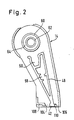
- Fig. 2 eine Innenansicht der rechten Gehäusehälfte des Druckwerks von Fig. 1,
- Fig. 3 eine Ansicht der Einstellwelle zur Verstellung der Typenträger,
- Fig. 4 einen Schnitt längs der Linie A-A von Fig. 3,
- Fig. 5 eine Ansicht des Betätigungsknopfs in der Darstellung von Fig. 1 von der rechten Seite her,
- Fig. 6 einen Schnitt längs der Linie B-B von Fig. 5,
- Fig. 7 einen Schnitt längs der Linie C-C von Fig. 5,
- Fig. 8 einen ebensolchen Schnitt wie in Fig. 6, jedoch mit eingesetztem Einstellglied,
- Fig. 9 eine Seitenansicht des Einstellglieds,
- Fig. 10 eine Unteransicht des Einstellglieds,
- Fig. 11 einen Axialschnitt durch einen auf das Ende einer Einstellwelle geschobenen Betätigungsknopf mit eingesetztem Einstellglied längs der Linie D-D in Fig. 12 in einer abgeänderten Ausführung,
- Fig. 12 eine Ansicht des Betätigungsknopfs und des Einstellwellenendes in der Ausführung von
- Fig. 11 von rechts bei abgenommenem Einstellglied, und
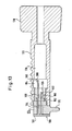
- Fig. 13 einen Axialschnitt durch den Betätigungsknopf, die Einstellwelle und einen damit verbundenen Mitnehmerträger in einer weiteren Ausführungs-form der Erfindung.
- 1 is an exploded view of a printing unit according to the invention,
- 2 is an interior view of the right half of the housing of the printing unit of FIG. 1,
- 3 is a view of the setting shaft for adjusting the type carrier,
- 4 shows a section along the line AA of FIG. 3,
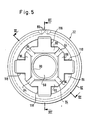
- 5 is a view of the actuating button in the representation of FIG. 1 from the right side,
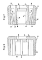
- 6 shows a section along the line BB of FIG. 5,
- 7 shows a section along the line CC of FIG. 5,
- 8 shows a section similar to that in FIG. 6, but with the adjusting member inserted,
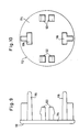
- 9 is a side view of the adjusting member,
- 10 is a bottom view of the setting member,
- 11 shows an axial section through an actuating button pushed onto the end of an adjusting shaft with an inserted adjusting element along the line DD in FIG. 12 in a modified embodiment,
- Fig. 12 is a view of the operating button and the setting shaft end in the embodiment of
- Fig. 11 from the right with the adjusting member removed, and
- 13 shows an axial section through the actuating button, the setting shaft and an associated carrier carrier in a further embodiment of the invention.
Das in Fig. 1 dargestellte Druckwerk 10 ist ein Stempeldruckwerk, bei dem als Typenträger Typenbänder 12 verwendet werden. Das Druckwerk enthält zwei Gehäusehälften 14 und 16, die über Schnapphaken 18 miteinander verbunden werden können. In der Gehäusehälfte 16 ist eine Einstellwelle 20 drehbar gelagert, über die eine geschlitzte Hülse 22 geschoben ist. Am Ende der Einstellwelle 20 angebrachte Mitnehmer 24 greifen durch Schlitze 26 in der Hülse 22 über deren Außenumfang hinaus. Auf dem Endbereich 28 der Einstellwelle 20 sitzen ein Fensterträger 30 und ein Betätigungsknopf 32, mit dessen Hilfe die Einstellwelle 20 gedreht und axial verschoben werden kann. Bei der Verschiebung der Einstellwelle 20 wird auch der Fensterträger 30 axial verschoben, und die Mitnehmer 24 gleiten axial längs der Schlitze 26 in der Hülse 22. Auf der Hülse 22 sitzen Einstellrader 34, die an ihrer eine zentrale Öffnung 35 umgebenden Innenumfangsflache Nuten 36 aufweisen, in die die Mitnehmer 24 der Einstellwelle 20 eingreifen. Durch axiales Verschieben der Einstellwelle 20 können die Mitnehmer 24 jeweils mit Nuten 36 eines Einstellrads 34 in Eingriff gebracht werden. Auf diese Weise kann durch Drehen des Betätigungsknopfs 32 nacheinander jedes der Einstellräder 34 gedreht werden. Die Einstellräder 34 sind an ihrer Außenumfangsfläche ebenfalls mit Nuten 38 versehen, in die an der Innenumfangsfläche der Typenbänder 12 angebrachte Vorsprünge 40 eingreifen. Auf diese Weise können die Typenbänder 12 über den Eingriff zwischen den Mitnehmern 24 und den Nuten 36 sowie den Eingriff zwischen den Nuten 38 und den Vorsprüngen 40 bewegt werden.The
Die Typenbänder 12 sind im Druckwerk um die Einstellräder 34 herumgelegt, und sie umgreifen außerdem einen an der unteren Stirnfläche der Gehäusehälfte 14 befindlichen, als Umlenkkante für die Typenbänder 12 dienenden Drucksteg 42. Die Drucktype, die sich bei der jeweiligen Ein stellung der Typenbänder 12 gerade unter dem Drucksteg 42 befindet, erzeugt jeweils den gewünschten Abdruck. In diesem Zusammenhang sei bemerkt, daß in Fig. 1 an den Typenbändern 12 nur einige der Ablesetypen dargestellt sind; die Drucktypen befinden sich auf der in Fig. 1 nicht erkennbaren Rückseite des von den Typenträgern 12 gebildeten Typenträgersatzes. Die erkennbaren Ablesetypen 44 und die jeweils zugeordneten Drucktypen sind auf den Typenbändern 12 so angebracht, daß immer dann, wenn sich eine Drucktype unterhalb des Druckstegs 42 in der Druckposition befindet, die entsprechende Ablesetype durch ein Fenster 46 im Fensterträger 30 sichtbar ist. Auf diese Weise ist durch das Fenster 46 hindurch stets erkennbar, welche Drucktypen sich gerade in der Druckposition unter dem Drucksteg 42 befinden.The
Nach Fig. 2 ist der Drucksteg 42 einstückig am unteren Ende eines mit der Gehäusehälfte 14 verbundenen Trägerelements 48 angebracht. An seinem oberen Ende weist das Trägerelement 48 eine Ausnehmung 50 auf, in der sich im zusammengebauten Zustand des Druckwerks ein Gummistreifen 52 und darüber eine Schraubenfeder 54 befinden. Der Gummistreifen 52 und die Schraubenfeder 54 haben zusammen eine solche Höhe, daß die Schraubenfeder 54 aus der Ausnehmung 50 nach oben herausragt und mit den darüber angeordneten Einstellrädern 34 in Kontakt kommt. Die Schraubenfeder 54 übt dabei eine begrenzte Haltekraft auf die Einstellräder aus, die deren Verdrehung entgegenwirkt. Wenn ein Einstellrad 34 durch Drehen der Einstellwelle 20 mittels des Betätigungsknopfs 32 gedreht wird, spürt die Bedienungsperson eine Rastkraft, die jeweils überwunden werden muß, um ein Typenband 12 schrittweise so zu verstellen, daß eine Drucktype nach der anderen unter dem Drucksteg 42 zu liegen kommt.2, the
Mittels eines Vierkantstücks 56, das in eine Ausnehmung 58 im Trägerelement 48 eingesetzt ist und dessen Breite der lichten Innenbreite der beiden Gehäusehälften 14, 16 entspricht, kann das Stempeldruckwerk beispielsweise mit einem Druckwerkträger eines Handetikettiergeräts verschraubt werden. Die entsprechenden, in Fig. 2 nicht dargestellten Schrauben können dabei durch Löcher in den Gehäusehälften 14, 16 gesteckt und in Gewindebohrungen in den Enden des Vierkantstücks 56 geschraubt werden.By means of a
Zur Lagerung der Hülse 22 in der Gehäusehälfte 14 sind zwei Ringbünde 60, 62 vorgesehen, deren radialer Abstand eine Ausnehmung 64 bildet, deren radiale Abmessung gleich der Wandstärke der Hülse 22 ist, so daß diese Hülse in die Ausnehmung geschoben und von den Ringbünden 60 und 62 gehalten werden kann. Der innere Ringbund 62 greift dabei innen in die Hülse 22 ein, während der äußere Ringbund 60 die Hülse 22 außen umfaßt. Die beiden Ringbünde haben nur eine geringe axiale Erstreckung, so daß sie jeweils nur das in Fig. 1 am weitesten rechts liegende Ende der Hülse 22 festhalten.To mount the
In Fig. 3 ist die Einstellwelle des Druckwerks von Fig. 1 in einer vergrößerten Ansicht dargestellt. Der für die Aufnahme des Betätigungsknopfs 32 bestimmte Endbereich 28 der Einstellwelle 20 hat einen teilweise quadratischen Querschnitt mit abgerundeten Ecken, so daß vier Rastflächen 66 entstehen. Unmittelbar am Ende weist die Einstellwelle 20 einen Wulst 68 und eine sich daran anschließende Umfangsnut 70 auf. Ein im Endbereich 28 der Einstellwelle 20 angebrachter diametraler Schlitz 72 erzeugt eine gewisse Elastizität dieses Endbereichs und eine Nachgiebigkeit des Wulsts 68. Der Wulst 68 und die Umfangsnut 70 haben den Zweck, den auf den Endbereich 28 geschobenen Betätigungsknopf 32 sicher festzuhalten, ohne daß dieser mit Hilfe zusätzlicher Mittel befestigt werden muß. Wie das Festhalten erfolgt, wird anschließend bei der Schilderung der Ausgestaltung des Betätigungsknopfs noch erkennbar werden.In Fig. 3, the setting shaft of the printing unit of Fig. 1 is shown in an enlarged view. The
Im zusammengebauten Zustand ragt der Endbereich 28 der Einstellwelle 20 durch eine Öffnung 74 in einer Seitenplatte 76 des Fensterträgers 30, wobei die Stufe 78 an der Einstellwelle 20 als Anschlag wirkt, die ein weiteres Hineinschieben der Einstellwelle 20 in die Öffnung 74 verhindert. Der Abschnitt des Endbereichs 28, der den quadratischen Querschnitt hat, ragt aus der Öffnung 74 in der Seitenplatte 76 in der Ansicht von Fig. 1 nach links heraus, so daß der Betätigungsknopf 32 auf den Endbereich aufgeschoben werden kann.In the assembled state, the
Nach den Fig. 5, 6 und 7 ist der Betätigungsknopf 32 an seiner Außenumfangsfläche leicht konisch ausgebildet, damit sein Anfassen und Betätigen erleichtert werden. Zur Erhöhung der Griffigkeit ist die Außenumfangsfläche geriffelt, was in Fig. 5 zur Vereinfachung der Darstellung nur mit Hilfe von zwei Riffelnuten 80 angedeutet ist. Der Betätigungsknopf 32 weist eine Außenhülse 82 und eine Innenhülse 84 auf, die mit der Außenhülse 82 an der Stirnfläche des Betätigungsknopfs 32 verbunden ist. Die Innenhülse 84 umgibt einen Innenhohlraum 88, der im Bereich der Stirnfläche 84 eine Verengung in Form eines Ringwulsts 90 hat. Wenn der Betätigungsknopf 32 auf die Einstellwelle aufgeschoben wird, drückt der Ringwulst 90 unter Ausnutzung der wegen des Schlitzes 72 gegebenen Nachgiebigkeit den Wulst 68 zusammen, bis der Ringwulst 90 in die Umfangsnut 70 gleitet. Der Wulst 68 kommt dann in der Erweiterung 92 im Betätigungsknopf 32 zu liegen, so daß der Betätigungsknopf 32 sicher auf der Einstellwelle 20 festgehalten wird.5, 6 and 7, the
Die Innenhülse 84 des Betätigungsknopfs 32 hat einen im wesentlichen quadratischen Querschnitt, wie in Fig. 5 zu erkennen ist. An den Ecken der quadratischen Form sind in Axialrichtung Schlitze 94 angebracht, so daß vier axial verlaufende Rastfinger 96 entstehen, die sich beim Aufschieben des Betätigungsknopfs 32 auf den Endbereich 28 der Einstellwelle 20 an die Rastflächen 66 anlegen. Wenn der Verdrehung der Einstellwelle 20 kein Widerstandsmoment entgegenwirkt, kann die Einstellwelle 20 mittels des aufgeschobenen Betätigungsknopfs 32 aufgrund der Zusammenwirkung der Rastfinger 96 mit den Rastflächen 66 gedreht werden. Die Rastfinger 96 sind aufgrund des Vorhandenseins der Schlitze 94 in radialer Richtung auslenkbar und wirken wie Federn, die eine bestimmte Federhärte haben. Diese Federhärte ist durch das Material und durch die konstruktive Ausgestaltung der Rastfinger festgelegt.The
Fig. 7 zeigt, daß die freien Enden der Rastfinger 96 über Verbindungsstege 98 mit der Außenhülse verbunden sind, wobei die Stelle, an der die Verbindungsstege mit der Außenhülse 82 verbunden sind, etwa in der Mitte der Längsersteckung der Außenhülse 82 liegt. Diese Verbindungsstege erhöhen die Federhärte der Rastfinger, üben sonst aber keinen Einfluß auf die sich wie einseitig eingespannte Blattfedern verhaltenden Rastfinger 96 aus.Fig. 7 shows that the free ends of the locking
Wie erwähnt, nimmt der auf die Einstellwelle 20 aufgeschobene Betatigungsknopf 32 diese bei einem Verdrehen mit, solange der Verdrehung der Einstellwelle 20 kein Widerstandsmoment entgegenwirkt. Das Druckwerk von Fig. 1 ist jedoch so ausgestaltet, daß die Typenbänder 12 beim Drehen der Einstellwelle 20 nur einen vorgegebenen Verstellweg ausführen können, wobei jedem weiteren Verdrehen ein sehr großes Widerstandsmoment entgegengesetzt wird. Dieses große Widerstandsmoment wird dadurch erzeugt, daß an der Innenumfangsfläche der Typenbänder 12 Vorsprünge 100 und 102 angebracht sind, die so dimensioniert sind, daß sie nicht durch einen Spalt 106 zwischen dem Drucksteg 42 und der Wand des Gehäuses 14 oder einen Spalt zwischen dem Drucksteg 42 und einem mit dem Gehäuse 14 verbundenen Anschlagsteg 108 hindurchpassen. Die beiden Vorsprünge 100 und 102 begrenzen damit den Verstellweg der Typenbänder in beiden Verstellrichtungen in der Weise, daß zwar alle Drucktypen unter den Drucksteg 42 gelangen können, nicht aber die den Drucktypen zugeordneten Ablesetypen 44. Wenn also ein Typenband so weit verstellt worden ist, daß der Vorsprung 100 in Anlage an die Oberkante 110 des Druckstegs 142 gekommen ist, steigt das dem weiteren Verdrehen entgegenwirkende Widerstandsmoment sehr stark an. Die Federhärte der Rastfinger 96 ist so dimensioniert, daß in dieser Situation eine Auslenkung der Federfinger 96 radial nach außen stattfindet, so daß die von den Rastfingern 96 ausgeübte Rastkraft überwunden wird und der Betätigungsknopf 32 auf dem Endbereich 28 der Einstellwelle 20 durchrutscht. Auf diese Weise wird verhindert, daß durch ein gewaltsames Weiterdrehen des Betätigungsknopfs 32 irgendwelche Beschädigungen des Druckwerks hervorgerufen werden.As mentioned, the
In der anderen Drehrichtung führt der Vorsprung 102 zum starken Ansteigen des Widerstandsmoments.In the other direction of rotation, the
Bei der Dimensionierung der Federhärte der Rastfinger 96 muß darauf geachtet werden, daß der Betätigungsgknopf 32 nicht bereits bei Ausübung des zur Verstellung der Typenbänder notwendigen Drehmoments durchzurutschen beginnt. Damit diese Forderung in optimaler Weise erfüllt wird, muß das Grenzdrehmoment, bei dem das Durchrutschen des Betätigungsknopfs 37 auf dem Endabschnitt 28 der Einstellwelle 20 beginnt, den jeweiligen Gegebenheiten angepaßt werden. Bei den schmalen Typenbändern 12, wie sie in Fig.1 dargestellt sind, ist das zum Verstellen aufzuwendende Drehmoment relativ gering, da die Typenbänder mit relativ geringer Kraft um den Drucksteg 42 herumgezogen werden können. Falls aber breitere Typenbänder zum Drucken grösserer Zahlen Anwendung finden, nimmt auch das zur Verstellung der Typenbänder notwendige Drehmoment zu. In diesem Fall muß das Grenzdrehmoment einen höheren Wert haben.When dimensioning the spring hardness of the locking
Zur Beeinflussung des Grenzdrehmoments und insbesondere zur Anpassung der Federhärte der Rastfinger 96 an ein höheres Grenzdrehmoment ist ein Einstellglied 112 vorgesehen, das anhand der Fig. 8, 9 und 10 erläutert wird. Das Einstellglied 112 weist eine kreisrunde Scheibe 114 auf, die mehrere Versteigungselemente 116 starr miteinander verbindet. Diese Versteifungselemente 116 stehen von der Scheibe 114 senkrecht ab, und sie sind in Öffnungen 118 in der Stirnwand 86 des Betätigungsknopfs 32 einschiebbar. Wie Fig. 8 zeigt, liegen die Versteifungselemente 116 im eingeschobenen Zustand an Rückflächen 120 der Rastfinger 96 an und bewirken dadurch eine Erhöhung der Federhärte dieser Rastfinger 96. Die Scheibe 114 des Einstellglieds 112 liegt dabei an der Stirnwand 86 des Betätigungsknopfs 32 an. Nach Fig. 9 und Fig. 10 sind an der Scheibe 114 zwei Versteifungselemente 116 angebracht, die mit zwei Rastfingern 96 zur Beeinflussung ihrer Federhärte in Eingriff gebracht werden können. An der Scheibe 114 sind auch Haltehaken 122 angebracht, die ebenso wie die Versteifungselemente 116 senkrecht abstehen. Diese Haltehaken dringen beim Einschieben der Versteifungselemente 116 in die Öffnungen 118 in entsprechende Öffnungen ein und bewirken ein Festhalten des Einstellglieds 112 am Betätigungsknopf 32.To influence the limit torque and in particular to adapt the spring hardness of the locking
Das Einstellglied 112 ermöglicht eine Einstellung der Federhärte der Rastfinger 96 in einem großen Einstellbereich. Je länger die Versteifungselemente 116 gemacht wer den, desto länger ist der Bereich, in dem sie an den Rückflächen 120 der Rastfinger 96 anliegen, und desto größer wird auch die Federhärte der Rastfinger 96. Außerdem ist es möglich, den Querschnitt der Versteifungselemente 116, der nach Fig. 10 T-förmig ist, zu verändern, so daß ein stärkerer oder schwächerer Versteifungseffekt erzielt wird. Anstelle der Verwendung von zwei Versteifungselementen, wie im beschriebenen Ausführungsbeispiel, könnten auch vier Versteifungselemente an der Scheibe 114 angebracht werden, so daß die Federhärte aller vier Rastfinger 96 erhöht werden kann. Somit kann mittels des Einstellglieds eine Anpassung des Grenzdrehmoments, bei dem der Betätigungsknopf 32 auf der Einstellwelle 20 durchzurutschen beginnt, an viele verschiedene Druckwerke erreicht werden, die aufgrund der Verwendung unterschiedlicher Typenträgersätze jeweils andere Grenzdrehmomente erfordern.The setting
In den Fig. 11 und 12 ist eine weitere Ausführungsform des Betätigungsknopfs und des mit ihm zusammenwirkenden Einstellwellen-Endbereichs dargestellt. Der Betätigungsknopf 132 hatdie Form eines Hohlzylinders, dessen Wand 133 auf ihrer Außenumfangsfläche zur Verbesserung der Griffigkeit mit Vorsprüngen 134 versehen ist. In einem mittleren Bereich sind an der Innenumfangsfläche der zylindrischen Wand 133 des Betätigungsknopfs 132 Vorsprünge136 und dazwischen jeweils Rastnuten 138 angebracht.11 and 12 show a further embodiment of the actuating button and of the adjusting shaft end region which interacts with it. The
Der den Bedienungsknopf 32 aufnehmende Endbereich 128 der Einstellewelle 140 weist in seiner eine Axialdurchführung 143 umgebenden zylindrischen Wand 141 acht Schlitze142 auf, so daß insgesamt acht sich axial erstreckende Rastelemente entstehen. Vier dieser Rastelemente bilden Rastfinger 144, während vier weitere Rastelemente, die jeweils zwischen zwei benachbarten Rastfingern 144 liegen, Sperrhaken 146 bilden. Wie in Fig. 11 zu erkennen ist, haben die Rastfinger 144 und die Sperrhaken 146 jeweils eine unterschiedliche axiale Erstreckung, die Sperrhaken reichen nämlich bis zur in Fig. 11 rechts liegenden Stirnfläche des Betätigungsknopfs 132, während die Rastfinger 144 nur so weit nach rechts ragen, wie auch die Vorsprünge 136 nach rechts verlaufen.The
Die Rastfinger 144 haben die gleiche Wirkung wie die Rastfinger 96 in der zuvor beschriebenen Ausführungsform. Sie verhindern ein freies Drehen des Betätigungsknopfs 132 auf dem Endbereich 128 der Einstellwelle 140. Aufgrund ihrer Federhärte setzen diese Rastfinger 144 dem Verdrehen des Betätigungsknopfs 132 relativ zur Einstellwelle 140 eine Rastkraft entgegen, die erst überwunden werden muß, damit eine relative Verdrehung ermöglicht wird. Die Federhärte der Rastfinger 144 ist so dimensioniert, daß die relative Verdrehung des Betätigungsknopfs 132 bezüglich der Einstellwelle 140 erst eintritt, wenn das von den Typenbändern 12 hervorgerufene Widerstandsmoment größer als das für ein normales Verstellen der Typenbänder aufzuwendende Drehmoment wird. Wie im zuvor beschriebenen Ausführungsbeispiel ist dies dann der Fall, wenn einer der Vorsprünge 100 oder 102 gegen die Oberkante des Druckstegs 42 läuft. Erst dann rutscht der Betätigungsknopf 132 auf dem Endbereich 128 der Einstellwelle 140 durch, wobei die Rastfinger 144 durch die Vorsprünge 136 radial nach innen ausgelenkt werden. Auf diese Weise wird bei Aufwendung eines über dem Grenzdrehmoment liegenden Drehmoments eine Beschädigung des Druckwerks verhindert.The locking
Die Sperrhaken 146 liegen gemäß Fig. 11 mit ihren radial nach außen gerichteten Zähnen 148 in einer Umfangsnut, die im in Fig. 11 rechts liegenden Ende der Zylinderwand des Betätigungsknopfs 132 angebracht ist. Beim Aufschieben des Betätigungsknopfs 132 auf die Einstellwelle 140 werden die Sperrhaken 148 radial nach innen ausgelenkt, bis sie in den Bereich der Nut 150 kommen, worauf sie wieder die in Fig. 11 dargestellte Lage einnehmen. In dieser Lage verhindern die Zähne 148, daß der Betätigungsknopf 132 ohne weiteres wieder von der Einstellwelle 140 abgezogen werden kann. Die Sperrhaken 146 halten den Betätigungsknopf 132 daher auf der Einstellwelle 140 fest.11, with their
Zur Veränderung des Grenzdrehmoments in Anpassung an den im Druckwerk jeweils verwendeten Typenträgersatz wird ein mit dem Einstellglied 112 vergleichbares Einstellglied 152 verwendet, das in den Innenhohlraum des Endbereichs 128 der Einstellwelle 140 gesteckt werden kann. Das Einstellglied 152 trägt an einer Seite einer Scheibe 154 vier Versteifungselemente und zwischen zwei benachbarten Versteifungselementen 156 jeweils ein Verriegelungsglied 158. Die Versteifungselemente 156 sind im Bereich ihrer Verbindung mit der Scheibe 154 bei 160 verdickt, so daß das Einstellglied 152 nur in einer solchen Lage eingesteckt werden kann, daß die Versteifungselemente 156 axial in einer Linie mit den Rastfingern 144 zu liegen kommen. Nur in dieser Position ist in der Nut 150 Platz für die bei 160 dargestellte Verdickung.In order to change the limit torque in adaptation to the type carrier set used in the printing unit in each case, an adjusting
Die Versteifungselemente 156 liegen mit ihrem Kopf 162 an den Rückflächen der Rastfinger 144 an, so daß sie deren Federhärte vergrößern, da die Rastfinger 144 nurmehr radial nach innen ausgelenkt werden können, wenn gleichzeitig auch die Versteifungselemente 156 nach innen ausgelenkt werden. Je nach der Länge der Versteifungselemente, also je nach der Lage des Kontaktbereichs zwischen dem Kopf 162 und der Rückfläche der Rastfinger 144 wird die Federhärte der Rastfinger 144 mehr oder weniger erhöht. Auch durch eine Verdickung der Versteifungselemente 156 kann die Auswir kung der Versteifungselemente 156 auf die Federhärte der Rastfinger 144 einwirken.The stiffening
Beim Einschieben des Einstellglieds 152 kommen die Verriegelungsglieder 158 in Anlage an die Rückflächen der Sperrhaken 148. Dadurch wird jegliche Auslenkung der Sperrhaken 148 radial nach innen verhindert, was dazu beiträgt, daß der Betätigungsknopf 132 sehr sicher auf dem Endbereich 128 der Einstellwelle 140 gehalten wird. Bei eingesetztem Einstellglied 152 kann der Betätigungsknopf 132 nicht von der Einstellwelle 140 abgezogen werden.When inserting the adjusting
In beiden beschriebenen Ausführungsformen wird durch die beschriebenen konstruktiven Ausgestaltungen der Betätigungsknöpfe und der Endbereiche der Einstellwellen erreicht, daß der Betätigungsknopf jeweils sicher auf der zugehörigen Einstellwelle gehalten wird und erst bei Überschreiten eines bestimmten Grenzdrehmoments relativ zur Einstellwelle verdreht werden kann. Mit Hilfe des jeweils vorgesehenen Einstellglieds kann durch Einwirkung auf die Federhärte der Rastfinger das Grenzdrehmoment den jeweiligen Anforderungen angepaßt werden.In both of the described embodiments, the described constructive designs of the actuating buttons and the end regions of the adjusting shafts ensure that the actuating button is held securely on the associated adjusting shaft and can only be rotated relative to the adjusting shaft when a certain limit torque is exceeded. With the aid of the adjusting element provided in each case, the limiting torque can be adapted to the respective requirements by acting on the spring hardness of the locking fingers.
In der in Figur 13 dargestellten Ausführungsform ist die das auf die Typenträger ibertragbare drehmomentbegrenzende Vorrichtung nicht zwischen dem Betätigungsknopf 170 und der Einstellwelle 172, sondern zwischen deren vom Betätigungsknopf 170 abgewandten Ende und einem zusätzlichen Bauteil angeordnet, nämlich einem Mitnehmerträger 174, der die Mitnehmer 176 trägt, die in die Nuten in den Innenumfangsflächen der Einstellräder 34 eingreifen.In the embodiment shown in FIG. 13, the torque-limiting device that can be transferred to the type carrier is not arranged between the
Der Mitnehmerträger 174 ist in die Axialdurchführung 178 der Einstellwelle 172 einsteckbar und er ist mit federnden Rastfingern 180 versehen, die in Rastnuten 182 eingreifen, die in der Innenumfangsfläche der Axialdurchführung 178 der Einstellwelle 172 eingreifen.The
Der Mitnehmerträger 174 weist ferner federnde Sperrhaken 184 auf, die in eine in der Innenumfangsfläche der Axialdurchführung 178 angebrachte Umfangsnut 186 eingreifen.The
Zur Beeinflussung der Federhärte der Rastfinger 180 und damit des auf die Einstellräder 34 übertragbaren Grenzdrehmoments ist ein Einstellglied 188 vorgesehen, das wie die Einstellglieder der zuvor beschriebenen Ausführungsformen durch eine Scheibe 190 starr miteinander verbundene Versteifungselemente aufweist, die durch eine axiale Öffnung 194 im Mitnehmerträger 174 eingeschoben werden können und im eingeschobenen Zustand in Anlage an die axial innenliegenden Flächen 196 der Rastfinger 180 kommen. Je nach der axialen Erstreckung und der Steifigkeit der Versteifungselemente 192 wird die Federhärte der Rastfinger 180 mehr oder weniger vergrößert.In order to influence the spring hardness of the latching
An der Scheibe 190 des Einstellglied 188 sind auch Verriegelungsglieder 198 angebracht, die ebenfalls in die Öffnung 194 im Mitnehmerträger 174 eingeschoben werden können und im eingeschobenen Zustand in Anlage an die axial innenliegenden Flächen 200 der Sperrhaken 184 kommen. Die Verriegelungsglieder 198 bewirken eine beträchtliche Versteifung der Sperrhaken 184, so daß der Mitnehmerträger 174 aufgrund der Zusammenwirkung der Sperrhaken 184 und der Umfangsnut 186 sehr sicher in der Einstellwelle 172 festgehalten wird.Locking
Durch die besondere Ausgestaltung des Mitnehmerträgers 174 wird somit erreicht, daß durch Einwirkung auf den Betätigungsknopf 170 nur ein bestimmtes Drehmoment auf die jeweils mit den Mitnehmers 176 in Eingriff stehenden Typenträger übertragen werden kann, so daß Beschädigungen des Druckwerks durch Aufwendung eines zu großen Drehmoments nach in Anlage kommen der den Verstellweg der Typenträger begrenzenden Anschlagmittel verhindert werden.The special design of the
In der Ausführungsform von Figur 13 kann mit einfachen Mitteln erreicht werden, daß bei verschiedenen Einstellpositionen der Einstellwelle 172 im Druckwerk unterschiedliche Grenzdrehmomente wirksam sind. Dies kann dann von Vorteil sein, wenn im Typenträgersatz gleichzeitig Typenträger vorhanden sind, zu deren Verstellung jeweils unterschiedliche Drehmomente erforderlich sind. Diese Anpassung an die unterschiedlichen Grenzdrehmomente kann mittels eines am Druckwerk gehäusefest angebrachten Stifts erreicht werden, der anstelle des Einstellglieds 188 in die Öffnung 194 des Mitnehmerträgers 174 ragt. Dieser Stift weist Umfangsbereiche mit verschiedenen axialen Längen auf, deren Radius jeweils gleich dem radialen Abstand zwischen der Achse der Einstellwelle 172 und der axial inneren Fläche 196 der Rastfinger 180 ist. In jeder axialen Einstellposition der Einstellwelle liegt einer der axialen Bereiche des Stifts an der axial inneren Fläche der Rastfinger 180 an und ibt dadurch die Wirkung der Versteifungselemente 92 aus. Indem die axiale Länge der Bereiche verändert wird, kann erreicht werden, daß bei den unterschiedlichen axialen Einstellpositionen der Einstellwelle 172 auch jeweils unterschiedliche Beeinflussungen der Rastfinger 180 erzielt werden. Wenn die axialen Längen der Bereiche des Stifts an die jeweiligen Verstellmomente der Typenträger angepaßt werden, ergibt sich beim Verstellen der Einstellwelle jeweils automatisch durch Zusammenwirken des jeweiligen Bereichs mit den Rastfingern das gewinschte, an den jeweiligen Typenträger angepaßte Grenzdrehmoment.In the embodiment of FIG. 13, it can be achieved by simple means that different limit torques are effective at different setting positions of the setting
Claims (18)
Priority Applications (1)
| Application Number | Priority Date | Filing Date | Title |
|---|---|---|---|
| AT87112468T ATE63862T1 (en) | 1986-10-21 | 1987-08-27 | PRINT UNIT. |
Applications Claiming Priority (2)
| Application Number | Priority Date | Filing Date | Title |
|---|---|---|---|
| DE3635732A DE3635732C1 (en) | 1986-10-21 | 1986-10-21 | Printing unit |
| DE3635732 | 1986-10-21 |
Publications (3)
| Publication Number | Publication Date |
|---|---|
| EP0264584A2 true EP0264584A2 (en) | 1988-04-27 |
| EP0264584A3 EP0264584A3 (en) | 1988-09-14 |
| EP0264584B1 EP0264584B1 (en) | 1991-05-29 |
Family
ID=6312125
Family Applications (1)
| Application Number | Title | Priority Date | Filing Date |
|---|---|---|---|
| EP87112468A Expired - Lifetime EP0264584B1 (en) | 1986-10-21 | 1987-08-27 | Printing unit |
Country Status (9)
| Country | Link |
|---|---|
| US (1) | US4744295A (en) |
| EP (1) | EP0264584B1 (en) |
| JP (1) | JPS63109081A (en) |
| AT (1) | ATE63862T1 (en) |
| AU (1) | AU576454B2 (en) |
| CA (1) | CA1278951C (en) |
| DE (2) | DE3635732C1 (en) |
| DK (1) | DK163421C (en) |
| NO (1) | NO163179C (en) |
Families Citing this family (5)
| Publication number | Priority date | Publication date | Assignee | Title |
|---|---|---|---|---|
| DE3635733A1 (en) * | 1986-10-21 | 1988-05-05 | Esselte Meto Int Gmbh | PRINT WORK |
| US5353704A (en) * | 1993-07-09 | 1994-10-11 | Wildewood Creative Products, Inc. | Stamping apparatus and method for forming a stamp and stamping using elongated members |
| TW415377U (en) * | 1996-12-24 | 2000-12-11 | Kazunosuke Makino | Character wheel, character wheel band and character wheel ring |
| WO2001020202A1 (en) | 1999-09-14 | 2001-03-22 | Mitsubishi Denki Kabushiki Kaisha | Oil control valve |
| JP4959619B2 (en) * | 2008-03-28 | 2012-06-27 | 株式会社サトー知識財産研究所 | Print selection device for printer and method for assembling operation member thereof |
Family Cites Families (8)
| Publication number | Priority date | Publication date | Assignee | Title |
|---|---|---|---|---|
| GB1402728A (en) * | 1971-06-23 | 1975-08-13 | Monarch Marking Systems Inc | Composite web of labels |
| JPS5947126B2 (en) * | 1976-06-25 | 1984-11-16 | 三菱自動車工業株式会社 | 2 cycle engine |
| US4323010A (en) * | 1979-11-19 | 1982-04-06 | Monarch Marking Systems, Inc. | Selective printing apparatus |
| JPS5712418U (en) * | 1980-06-26 | 1982-01-22 | ||
| JPS584461Y2 (en) * | 1980-07-11 | 1983-01-25 | 橋本 和雄 | Dehydration device for endless “su” type seaweed making machine |
| DE3406762C1 (en) * | 1984-02-24 | 1985-11-14 | Esselte Pendaflex Corp., Garden City, N.Y. | Printing unit |
| DE3406791C1 (en) * | 1984-02-24 | 1985-11-14 | Esselte Pendaflex Corp., Garden City, N.Y. | Printing unit |
| DE3635733A1 (en) * | 1986-10-21 | 1988-05-05 | Esselte Meto Int Gmbh | PRINT WORK |
-
1986
- 1986-10-21 DE DE3635732A patent/DE3635732C1/en not_active Expired
- 1986-11-24 US US06/934,034 patent/US4744295A/en not_active Expired - Lifetime
-
1987
- 1987-08-27 AT AT87112468T patent/ATE63862T1/en not_active IP Right Cessation
- 1987-08-27 DE DE8787112468T patent/DE3770405D1/en not_active Expired - Lifetime
- 1987-08-27 EP EP87112468A patent/EP0264584B1/en not_active Expired - Lifetime
- 1987-10-07 CA CA000548780A patent/CA1278951C/en not_active Expired - Lifetime
- 1987-10-07 AU AU79442/87A patent/AU576454B2/en not_active Ceased
- 1987-10-14 NO NO874294A patent/NO163179C/en unknown
- 1987-10-21 JP JP62266151A patent/JPS63109081A/en active Pending
- 1987-10-21 DK DK552087A patent/DK163421C/en not_active IP Right Cessation
Also Published As
| Publication number | Publication date |
|---|---|
| EP0264584A3 (en) | 1988-09-14 |
| DE3770405D1 (en) | 1991-07-04 |
| DK163421B (en) | 1992-03-02 |
| DE3635732C1 (en) | 1988-02-25 |
| JPS63109081A (en) | 1988-05-13 |
| DK552087A (en) | 1988-04-22 |
| DK163421C (en) | 1992-07-20 |
| AU7944287A (en) | 1988-05-05 |
| DK552087D0 (en) | 1987-10-21 |
| EP0264584B1 (en) | 1991-05-29 |
| NO874294D0 (en) | 1987-10-14 |
| AU576454B2 (en) | 1988-08-25 |
| ATE63862T1 (en) | 1991-06-15 |
| NO874294L (en) | 1988-04-22 |
| NO163179C (en) | 1990-04-18 |
| US4744295A (en) | 1988-05-17 |
| CA1278951C (en) | 1991-01-15 |
Similar Documents
| Publication | Publication Date | Title |
|---|---|---|
| DE2623268C2 (en) | Cutter | |
| DE2817952C2 (en) | ||
| DE102018100054A1 (en) | Lockable torque wrench with a beep | |
| DE2265449C3 (en) | Device for the selectable setting of several type carriers of a stamp in a label dispenser | |
| DE4442533A1 (en) | Drilling device | |
| DE2820412A1 (en) | COUPLING | |
| DE2441141C2 (en) | Pressure device for a diaphragm spring clutch | |
| DE3427858C2 (en) | Printing unit | |
| EP0264584B1 (en) | Printing unit | |
| EP0264585B1 (en) | Printing unit | |
| DE3406762C1 (en) | Printing unit | |
| DE19652094C1 (en) | Adjustment device for a radiator valve | |
| DE3406822C1 (en) | Printing unit | |
| EP0264583B1 (en) | Printing unit | |
| DE2730475A1 (en) | SINGLE DRIVE FOR FINE MECHANICAL DEVICES, IN PARTICULAR THERMOSTATS | |
| EP0775661A1 (en) | Transport element for flat articles | |
| DE4301499C2 (en) | Slider for a wall bar | |
| DE3406791C1 (en) | Printing unit | |
| DE1914476B2 (en) | HUB FOR REEL BODY | |
| DE2113917A1 (en) | Fastener | |
| DE4318139C2 (en) | Fastening device | |
| DE3605301C2 (en) | ||
| DE3127382C2 (en) | Switching device for a platen | |
| DE69304017T2 (en) | Connector assembly | |
| DE2731096C3 (en) | Device for extending a drive shaft with a square cross-section |
Legal Events
| Date | Code | Title | Description |
|---|---|---|---|
| PUAI | Public reference made under article 153(3) epc to a published international application that has entered the european phase |
Free format text: ORIGINAL CODE: 0009012 |
|
| AK | Designated contracting states |
Kind code of ref document: A2 Designated state(s): AT BE CH DE ES FR GB GR IT LI NL SE |
|
| RAP1 | Party data changed (applicant data changed or rights of an application transferred) |
Owner name: ESSELTE METO INTERNATIONAL PRODUKTIONS GMBH |
|
| PUAL | Search report despatched |
Free format text: ORIGINAL CODE: 0009013 |
|
| AK | Designated contracting states |
Kind code of ref document: A3 Designated state(s): AT BE CH DE ES FR GB GR IT LI NL SE |
|
| 17P | Request for examination filed |
Effective date: 19881103 |
|
| 111L | Licence recorded |
Free format text: 0100 ESSELTE METO, S.N.C. |
|
| 17Q | First examination report despatched |
Effective date: 19900420 |
|
| GRAA | (expected) grant |
Free format text: ORIGINAL CODE: 0009210 |
|
| AK | Designated contracting states |
Kind code of ref document: B1 Designated state(s): AT BE CH DE ES FR GB GR IT LI NL SE |
|
| PG25 | Lapsed in a contracting state [announced via postgrant information from national office to epo] |
Ref country code: SE Effective date: 19910529 Ref country code: NL Effective date: 19910529 Ref country code: GR Free format text: LAPSE BECAUSE OF FAILURE TO SUBMIT A TRANSLATION OF THE DESCRIPTION OR TO PAY THE FEE WITHIN THE PRESCRIBED TIME-LIMIT Effective date: 19910529 Ref country code: GB Effective date: 19910529 Ref country code: BE Effective date: 19910529 |
|
| REF | Corresponds to: |
Ref document number: 63862 Country of ref document: AT Date of ref document: 19910615 Kind code of ref document: T |
|
| ITF | It: translation for a ep patent filed | ||
| REF | Corresponds to: |
Ref document number: 3770405 Country of ref document: DE Date of ref document: 19910704 |
|
| ET | Fr: translation filed | ||
| PG25 | Lapsed in a contracting state [announced via postgrant information from national office to epo] |
Ref country code: AT Effective date: 19910827 |
|
| PG25 | Lapsed in a contracting state [announced via postgrant information from national office to epo] |
Ref country code: LI Effective date: 19910831 Ref country code: CH Effective date: 19910831 |
|
| PG25 | Lapsed in a contracting state [announced via postgrant information from national office to epo] |
Ref country code: ES Free format text: LAPSE BECAUSE OF FAILURE TO SUBMIT A TRANSLATION OF THE DESCRIPTION OR TO PAY THE FEE WITHIN THE PRESCRIBED TIME-LIMIT Effective date: 19910909 |
|
| NLV1 | Nl: lapsed or annulled due to failure to fulfill the requirements of art. 29p and 29m of the patents act | ||
| GBV | Gb: ep patent (uk) treated as always having been void in accordance with gb section 77(7)/1977 [no translation filed] | ||
| PLBE | No opposition filed within time limit |
Free format text: ORIGINAL CODE: 0009261 |
|
| STAA | Information on the status of an ep patent application or granted ep patent |
Free format text: STATUS: NO OPPOSITION FILED WITHIN TIME LIMIT |
|
| REG | Reference to a national code |
Ref country code: CH Ref legal event code: PL |
|
| 26N | No opposition filed | ||
| REG | Reference to a national code |
Ref country code: FR Ref legal event code: CL |
|
| PGFP | Annual fee paid to national office [announced via postgrant information from national office to epo] |
Ref country code: FR Payment date: 20041223 Year of fee payment: 18 Ref country code: DE Payment date: 20041223 Year of fee payment: 18 |
|
| PG25 | Lapsed in a contracting state [announced via postgrant information from national office to epo] |
Ref country code: IT Free format text: LAPSE BECAUSE OF NON-PAYMENT OF DUE FEES;WARNING: LAPSES OF ITALIAN PATENTS WITH EFFECTIVE DATE BEFORE 2007 MAY HAVE OCCURRED AT ANY TIME BEFORE 2007. THE CORRECT EFFECTIVE DATE MAY BE DIFFERENT FROM THE ONE RECORDED. Effective date: 20050827 |
|
| PG25 | Lapsed in a contracting state [announced via postgrant information from national office to epo] |
Ref country code: DE Free format text: LAPSE BECAUSE OF NON-PAYMENT OF DUE FEES Effective date: 20060301 |
|
| PG25 | Lapsed in a contracting state [announced via postgrant information from national office to epo] |
Ref country code: FR Free format text: LAPSE BECAUSE OF NON-PAYMENT OF DUE FEES Effective date: 20060428 |
|
| REG | Reference to a national code |
Ref country code: FR Ref legal event code: ST Effective date: 20060428 |