EP0264285B1 - Appareil de reproduction d'information magnéto-optique - Google Patents
Appareil de reproduction d'information magnéto-optique Download PDFInfo
- Publication number
- EP0264285B1 EP0264285B1 EP87309127A EP87309127A EP0264285B1 EP 0264285 B1 EP0264285 B1 EP 0264285B1 EP 87309127 A EP87309127 A EP 87309127A EP 87309127 A EP87309127 A EP 87309127A EP 0264285 B1 EP0264285 B1 EP 0264285B1
- Authority
- EP
- European Patent Office
- Prior art keywords
- magneto
- light
- optical
- photodetectors
- recording medium
- Prior art date
- Legal status (The legal status is an assumption and is not a legal conclusion. Google has not performed a legal analysis and makes no representation as to the accuracy of the status listed.)
- Expired - Lifetime
Links
- 230000003287 optical effect Effects 0.000 claims description 29
- 238000002834 transmittance Methods 0.000 claims description 23
- 238000001514 detection method Methods 0.000 claims description 14
- 230000009471 action Effects 0.000 claims description 7
- 230000000694 effects Effects 0.000 claims description 7
- 238000012545 processing Methods 0.000 claims description 7
- 230000008033 biological extinction Effects 0.000 claims description 4
- 238000006243 chemical reaction Methods 0.000 claims description 4
- 230000014509 gene expression Effects 0.000 description 12
- 239000004065 semiconductor Substances 0.000 description 11
- 230000009467 reduction Effects 0.000 description 9
- 101100234408 Danio rerio kif7 gene Proteins 0.000 description 8
- 101100221620 Drosophila melanogaster cos gene Proteins 0.000 description 8
- 101100398237 Xenopus tropicalis kif11 gene Proteins 0.000 description 8
- 230000010287 polarization Effects 0.000 description 6
- 238000010276 construction Methods 0.000 description 5
- 230000005540 biological transmission Effects 0.000 description 4
- 230000005374 Kerr effect Effects 0.000 description 3
- 101150118300 cos gene Proteins 0.000 description 3
- 230000006870 function Effects 0.000 description 3
- 230000015654 memory Effects 0.000 description 2
- 238000010521 absorption reaction Methods 0.000 description 1
- 230000008901 benefit Effects 0.000 description 1
- 238000007796 conventional method Methods 0.000 description 1
- 230000007423 decrease Effects 0.000 description 1
- 238000013461 design Methods 0.000 description 1
- 238000011156 evaluation Methods 0.000 description 1
- 230000006872 improvement Effects 0.000 description 1
- 230000005415 magnetization Effects 0.000 description 1
- 238000000034 method Methods 0.000 description 1
- 230000004048 modification Effects 0.000 description 1
- 238000012986 modification Methods 0.000 description 1
- 210000001747 pupil Anatomy 0.000 description 1
- 238000007493 shaping process Methods 0.000 description 1
- 230000003746 surface roughness Effects 0.000 description 1
- 239000010409 thin film Substances 0.000 description 1
Images


Classifications
-
- G—PHYSICS
- G11—INFORMATION STORAGE
- G11B—INFORMATION STORAGE BASED ON RELATIVE MOVEMENT BETWEEN RECORD CARRIER AND TRANSDUCER
- G11B11/00—Recording on or reproducing from the same record carrier wherein for these two operations the methods are covered by different main groups of groups G11B3/00 - G11B7/00 or by different subgroups of group G11B9/00; Record carriers therefor
- G11B11/10—Recording on or reproducing from the same record carrier wherein for these two operations the methods are covered by different main groups of groups G11B3/00 - G11B7/00 or by different subgroups of group G11B9/00; Record carriers therefor using recording by magnetic means or other means for magnetisation or demagnetisation of a record carrier, e.g. light induced spin magnetisation; Demagnetisation by thermal or stress means in the presence or not of an orienting magnetic field
- G11B11/105—Recording on or reproducing from the same record carrier wherein for these two operations the methods are covered by different main groups of groups G11B3/00 - G11B7/00 or by different subgroups of group G11B9/00; Record carriers therefor using recording by magnetic means or other means for magnetisation or demagnetisation of a record carrier, e.g. light induced spin magnetisation; Demagnetisation by thermal or stress means in the presence or not of an orienting magnetic field using a beam of light or a magnetic field for recording by change of magnetisation and a beam of light for reproducing, i.e. magneto-optical, e.g. light-induced thermomagnetic recording, spin magnetisation recording, Kerr or Faraday effect reproducing
- G11B11/10532—Heads
- G11B11/10541—Heads for reproducing
- G11B11/10543—Heads for reproducing using optical beam of radiation
Definitions
- the present invention relates to a magneto-optical information reproducing apparatus which utilizes the magneto-optical effect to reproduce information magnetically recorded on a recording medium.
- magneto-optical disks capable of erasing and re-writing have been regarded as promising with optical disks exclusively for reproduction typified by compact disks and direct read after write (DRAW) type optical disks.
- Magneto-optical disks are such that information is magnetically recorded by the utilization of the localized temperature size of a magnetic thin film caused by the application of a laser spot thereto and the information is reproduced by the magneto-optical effect (particularly the Kerr effect).
- the Kerr effect refers to the phenomenon that the plane of polarization is rotated when light is reflected by a magnetic recording medium.
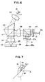
- FIG. 1 The basic construction of a magneto-optical disk apparatus according to the prior art is shown in Figure 1 of the accompanying drawings.
- the reference numeral 1 designates a semiconductor laser
- the reference numeral 2 denotes a collimator lens
- the reference numerals 11 and 20 designate half-mirrors
- the reference numeral 4 denotes an objective lens
- the reference numeral 6 designates a magneto-optical recording medium
- the reference numerals 71 and 72 denote analyzers
- the reference numeral 8 designates a condensing lens
- the reference numerals 91 and 92 denote photodetectors.
- the direction of P-polarization is parallel to the plane of the drawing sheet
- the direction of S-polarization is perpendicular to the plane of the drawing sheet.
- a light beam emitted from the semiconductor laser 1 as a rectilinearly polarized light in the direction of P-polarization is collimated by the collimater lens 2 and passes through the half-mirror 11. If the P-polarized component amplitude transmittance is t p and the S-polarized component amplitude transmittance is t s ,
- 2
- 2 0.5 in the half-mirror 11. The light beam is imaged as a minute spot on the magneto-optical recording medium 6 by the objective lens 4.
- the P-polarized component of the amplitude reflectance of the recording medium 6 is R and the S-polarized component is K
- the following equation is established:
- the magneto-optically modulated reflected light is again collimated by the objective lens 4 and reflected by the half-mirror 11, whereafter it is made into a convergent light beam by the condensing lens 8 and divided by the half-mirror 20, and the divided lights pass through the analyzers 71 and 72, respectively, and are detected as intensity-modulated light beams by the photodetectors 91 and 92.
- the angle of the optic axis of the analyzer with respect to the direction of P-polarization is ⁇ A on the transmission side and the reflection side, and the light beam is analyzed as a regular projection of the amplitude thereof onto the optic axis of the analyzer.
- the azimuth angle ⁇ A of the optic axis of the analyzer be set to such an optimum position that the C/N (the ratio between the carrier wave and the noise) of the detection signal becomes maximum.
- the C/N the ratio between the carrier wave and the noise
- U.S. Patent No. 4,569,035 issued on February 4, 1986, there is shown an example of an apparatus using as a photodetector an avalanche photodiode (APD) of the like having a multiplying action wherein the azimuth of the transmission axis (the optic axis) of the analyzer is optimized.
- APD avalanche photodiode
- the azimuth angle ⁇ A of the optic axis of the analyzer has been set to 45° so that the signal light becomes maximum.
- equation (2) can be expressed as follows:
- the second term in the parentheses is the magneto-optical modulated component and the first term in the parentheses is the non-modulated component.
- a magneto-optical information reproducing apparatus comprising means for applying a light beam polarized in a predetermined direction onto a recording medium on which information is magnetically recorded, means for dividing the reflected or transmitted light beam from said recording medium modulated into a polarized state in conforming with said information by the magneto-optical effect, a pair of analyzer means having their optic axes inclined in opposite directions with respect to said predetermined direction and analyzing said divided light beams, a pair of photodetectors having no amplifying action and photoelectrically detecting the light beams transmitted through said pair of analyzer means, and a signal processing means for amplifying the detection signals of said pair of photodetectors, subtracting them from each other and reproducing said information, characterized in that the angle ⁇ A formed between the optic axes of said plurality of analyzer means and said predetermined direction satisfies the following conditions: where I0 is the quantity of light of the incident light beam on said recording medium, R is the amplitude
- Figure 1 schematically shows an example of a magneto-optical information reproducing apparatus according to the prior art.
- Figure 2 illustrates the principle of the general magneto-optical signal detection.
- Figure 3 schematically shows an optical system according to an embodiment of the present invention.
- Figure 4 schematically shows a signal processing system in the embodiment shown in Figure 3.
- FIGS 5 and 6 schematically show another embodiment of the present invention.
- Figure 7 shows the polarized state of the reflected light from a magneto-optical recording medium.
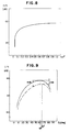
- Figures 8 and 9 are graphs showing the relation between the polarizing characteristic of a polarizing beam splitter in the present invention and C/N.
- FIGS 10A and 10B schematically show still another embodiment of the present invention.
- Figures 3 and 4 show a first embodiment of a magneto-optical information reproducing apparatus according to the present invention, and more particularly, Figure 3 schematically shows the construction of an optical system and Figure 4 schematically shows the construction of a signal processing circuit.
- the reference numeral 21 designates a semiconductor laser
- the reference numeral 22 denotes a collimator lens
- the reference numeral 12 designates a polarizing beam splitter
- the reference numeral 24 denotes an objective lens
- the reference numeral 26 designates a magneto-optical recording medium
- the reference numeral 271 and 272 denote analyzers
- the reference numeral 28 designates a condensing lens
- the reference numerals 291 and 292 denote photodetectors such as PIN photodiodes having no amplifying action
- the reference numeral 30 designates a half-mirror.
- the direction of P-polarization is parallel to the plane of the drawing sheet, and the direction of S-polarization is perpendicular to the plane of the drawing sheet.
- the reference numerals 13 and 14 designate light beams transmitted through the analyzers 271 and 272.
- the detection light beams 13 and 14, as shown in Figure 4, photoelectrically converted by the photodetectors 291 and 292, and voltage-amplified by amplifiers 151 and 152 including load resistors 161 and 162, whereafter they are subtracted from each other by a differential amplifier 18 and output as a reproducing signal from a terminal 14.
- the semiconductor laser 21 emits a P-polarized light beam.
- This emitted light beam is collimated by the collimator lens 22, is transmitted through the polarizing beam splitter and is applied as a light spot of intensity I0 onto the recording medium 26 by the objective lens 24.
- the light beam reflected by the recording medium 26 is modulated into a polarized state in conformity with the information magnetically recorded on the recording medium 26, again passes through the objective lens 24, is reflected by the polarizing beam splitter 12, is made into a convergent light beam by the condensing lens 28 and is directed to the half-mirror 30.
- the light beams reflected by and transmitted through the half-mirror 30 pass through the analyzers 271 and 272, respectively, and are intensity-modulated thereby and received by the photodetectors, 291 and 292.
- the intensities I t and I r of the detection lights 13 and 14 can be expressed as follows in a case where the Kerr rotation angle is + ⁇ k : With
- the second term in the parentheses is the magneto-optical modulated component and the first term in the parentheses is the non-modulated component.
- ⁇ indicates the photoelectric conversion efficiency and is given by the following equation: where e is the amount of charge, h is the plank constant, ⁇ is the quantum efficiency of the photodetectors and ⁇ is the number of vibration of the light beam.
- the magneto-optical modulated component intensity is I k and the non-modulated component intensity is I R ' these are expressed as follows; I R ⁇ I0
- the noise by ⁇ I2 k mentioned under item 1)above is offset by effecting differential detection, but the noises mentioned under items 2), 3) and 4) above remain and particularly, the thermal noise becomes twice because there are provided two amplifiers.
- C/N can be expressed in decibel indication as follows:
- the C/N of equation (17) is a function of the amplitude reflectances r p and r s of the polarizing beam splitter and the angle ⁇ A of the optic axis of the analyzers with respect to the direction of P-polarization and therefore, equation (17) is differentiated by
- 2 1 (18) and with regard to
- 2I0 ⁇ B (21) t
- Figure 5 schematically shows the construction of an optical system according to a second embodiment of the present invention.
- the present embodiment is a modification of the aforedescribed first embodiment in which the light beam transmitted through the polarizing beam splitter 12 may be detected.
- members similar to those in Figure 3 are given similar reference numerals and need not be described in detail.
- the signal processing circuit may be one similar to that shown in Figure 4.
- Equation (17) is a function of the amplitude transmittances t s and t p of the polarizing beam splitter and the inclination ⁇ A of the optic axis of the analyzers with respect to the direction of S-polarization and therefore, equation (17) may be differentiated by
- the extremal value found is ⁇ (C/N) / ⁇ (
- 2 1 (25) and with regard to
- 2I0 ⁇ B (28) t T (29) If by the use of a polarizing beam splitter having a polarizing characteristic which will satisfy expressions (25) - (29), the optic axis of the analyzers is inclined with respect to the direction of S-polarization, C/N can be made a maximum value. However, in expression (26), the incident light is caused to enter in the direction of S-polarization and therefore, actually, this expression is impossible and a suitable value must be determined.
- Figure 6 schematically shows a third embodiment of the present invention.
- members similar to those in Figure 3 are given similar reference numerals and need not be described in detail.
- the signal processing system subsequent to the photo-detectors 29 is constructed as shown in Figure 4.
- a polarizing beam splitter 23 having the beam shaping function is used instead of the polarizing beam splitter 12 in the first embodiment.
- the surface a of the polarizing beam splitter 23 is inclined by a predetermined angle so that stray light may not enter the photodetectors 29.
- tracking grooves (not shown) are formed in a direction perpendicular to the plane of the drawing sheet, and the light beam condensed on the recording medium 26 by the objective lens 24 is diffracted by these grooves.
- the reference numeral 25 designates a photodetector for detecting any unbalance of ⁇ 1st-order diffracted lights caused by track deviation.
- the photodetector 25 is fixed to the marginal edge of an opening in the objective lens 24. This leads to the advantage that no offset is caused to the tracking error signal even if the objective lens 24 is moved in the tracking grooves in a direction perpendicular thereto.
- the photodetectors 29 are photodetectors having no amplifying action such as Si-PIN photodiodes, and effect the detection of a magneto-optical signal and a focus error signal.
- a conventional method is used for the detection of the focus error, but it has no direct relation with the present invention and therefore need not be described in detail.
- the light utilization efficiency ⁇ R is defined. It should be noted that in the present invention, as the light utilization efficiency, attention is paid to the ratio between the quantity of light on the recording medium and the quantity of light reading the photodetectors. In the present embodiment, when finding ⁇ R , the following points have been taken into consideration:
- the light utilization efficiency ⁇ k is defined to evaluate the reduction in the intensity of the magneto-optical modulated component, and when finding ⁇ k , the following point has been taken into account.
- the light utilization efficiency is defined as ⁇ 2 with the product along the optical path of the P and S polarization direction amplitude transmittances (or reflectances) of n optical elements except the polarizing beam splitter and the analyzers present in the optical path leading from the recording medium to the photodetectors being taken into consideration.
- Equation (34) ⁇ i is expressed as follows: In equation (35), where the light beam is reflected by the i th optical element,
- the polarizing characteristic of the polarizing beam splitter and the transmittance of the analyzers are handled as an amount of variation during the calculation of C/N and are therefore excepted from ⁇ 2.
- ⁇ k ⁇ 0 ⁇ 2 (36)
- the P and S polarization direction amplitude reflectances are r p and r s , respectively, then where ⁇ and ⁇ are the phase components of respective amplitude reflectances. More accurate evaluation is also made of the analyzers.
- 2 of the polarizing beam splitter so that the quantity of incident light on the recording medium 26 is I0 2 x 10 ⁇ 3W .
- GdTbFeCo is used as the recording medium 26,
- the product of P and S amplitude transmittances of the optical elements except the polarizing beam splitter and the analyzers present in the optical path leading from the recording medium to the photodetectors may be taken into consideration.
- and hence, ⁇ 2 0.79.
- the thermal noise T cannot be described in such a simple form as shown in equation (14) depending on the capacity or the like of the photodetectors and therefore, in such cases, T need not conform to such form.
- Figure 9 shows the comparison of the present embodiment with a conventional apparatus using a half-mirror as to C/N with
- 2 0.3 and
- 2 1, respectively.
- the ordinate represents C/N and the abscissa represents ⁇ A .
- the conventional apparatus indicated by dot-and-dash line
- the present embodiment is improved over 4dB in C/N.
- ⁇ A 65° which maximizes C/N, but in the present embodiment, C/N is further improved over 2dB.
- Figures 10A and 10B schematically show a fourth embodiments of the present invention, Figure 10B being a view in which Figure 10A is seen in the direction of arrow.
- Figures 10A and 10B members similar to those in Figure 6 are given similar reference numerals and need not be described in detail.
- the signal processing system subsequent to the photodetectors 29 is constructed as shown in Figure 4.
- the present embodiment uses a polarizing beam splitter 10 instead of the polarizing beam splitter 23 in the third embodiment and is designed such that the light transmitted through the polarizing beam splitter 10 is detected.
- the surface b of the polarizing beam splitter 10 is inclined by a predetermined angle so that stray light may not enter the photodetectors 29.
- the intensities of the magneto-optical modulated component and non-modulated component are I k and I R , respectively, they can be expressed as follows: IR ⁇ I0 ⁇ 0 ⁇ 1
- 2 (cos2 ⁇ A + ⁇ A sin2 ⁇ A) I0 ⁇ R
- the polarizing characteristic of the polarizing beam splitter which maximizes C/N and the angle ⁇ A of the optic axis of the analyzers with respect to the direction of P-polarization are found as follows.
- the present invention permits various applications besides the above-described embodiments.
- the reflected light from the magneto-optical recording medium is detected, but alternatively, design may be made such that the light beam transmitted through the magneto-optical recording medium and modulated by the Faraday effect is detected.
- the present invention covers all such applications without departing from the scope thereby as defined in the appended claims.
Claims (5)
- Appareil de reproduction magnéto-optique d'informations, comportant des moyens (10,12,21-24) destinés à appliquer un faisceau lumineux, polarisé dans une direction prédéterminée, sur un support d'enregistrement (26) sur lequel une information est enregistrée magnétiquement, des moyens (30) destinés à diviser le faisceau lumineux réfléchi ou transmis, provenant du support d'enregistrement et modulé en un état polarisé en conformité avec ladite information par l'effet magnéto-optique, deux moyens analyseurs (27₁,27₂) ayant leurs axes optiques inclinés dans des directions opposées par rapport à ladite direction prédéterminée et analysant lesdits faisceaux lumineux divisés, deux photodétecteurs (29₁,29₂) n'ayant aucune action d'amplification et réalisant une détection photoélectrique des faisceaux lumineux transmis à travers les deux moyens analyseurs, et des moyens de traitement de signaux (15₁, 15₂, 16₁, 16₂, 18) destinés à amplifier les signaux de détection des deux photodétecteurs, à les soustraire l'un de l'autre et à reproduire ladite information, caractérisé en ce que l'angle ϑA formé entre les axes optiques des moyens analyseurs et ladite direction prédéterminée satisfait les conditions suivantes :


où I₀ est la quantité de lumière du faisceau lumineux incident sur ledit support d'enregistrement, R est la réflectance d'amplitude dudit support d'enregistrement, ε est le rendement d'utilisation de la lumière du système optique allant du support d'enregistrement jusqu'aux photodétecteurs à l'exception desdits moyens analyseurs, K est le rendement de conversion photoélectrique desdits photodétecteurs, e est la quantité de charge, S est le bruit de grenaille desdits photodétecteurs, T est le bruit thermique desdits moyens d'amplification dans une fréquence d'observation du signal magnéto-optique, ΔB est la bande passante de la fréquence d'observation du signal magnéto-optique, tA est la transmittance d'amplitude desdits moyens analyseurs, et ηA est le rapport d'extinction desdits moyens analyseurs. - Appareil de reproduction magnéto-optique d'informations selon la revendication 1, comportant en outre un diviseur (12) de faisceau à polarisation destiné à réfléchir le faisceau lumineux provenant dudit support (26) et à le diriger sur lesdits moyens (30) de division, et dans lequel la réflectance d'amplitude rp dudit diviseur de faisceau à polarisation pour la composante polarisée dans ladite direction prédéterminée et la réflectance d'amplitude rs dudit diviseur de faisceau à polarisation pour la composante polarisée dans une direction perpendiculaire à ladite direction prédéterminée satisfont les conditions suivantes, respectivement :


- Appareil de reproduction magnéto-optique d'informations selon la revendication 1, comportant en outre un diviseur (12) de faisceau à polarisation destiné à transmettre à travers lui le faisceau lumineux provenant dudit support et à le diriger sur lesdits moyens (30) de division, et dans lequel la transmittance d'amplitude ts dudit diviseur de faisceau à polarisation pour la composante polarisée dans ladite direction prédéterminée et la transmittance d'amplitude tp dudit diviseur de faisceau à polarisation pour la composante polarisée dans une direction perpendiculaire à ladite direction prédéterminée satisfont les conditions suivantes, respectivement :

- Appareil de reproduction magnéto-optique d'informations selon la revendication 1, dans lequel lesdits moyens destinés à appliquer un faisceau lumineux comprennent une source de lumière (21) et un système optique (22) destiné à condenser sur ledit support (26) le faisceau lumineux émis par ladite source de lumière.
- Appareil de reproduction magnéto-optique d'informations selon la revendication 1, dans lequel lesdits photodétecteurs (29₁, 29₂) sont des photodiodes PIN.
Applications Claiming Priority (2)
| Application Number | Priority Date | Filing Date | Title |
|---|---|---|---|
| JP246614/86 | 1986-10-17 | ||
| JP61246614A JPH0778916B2 (ja) | 1986-10-17 | 1986-10-17 | 光磁気情報再生装置 |
Publications (3)
| Publication Number | Publication Date |
|---|---|
| EP0264285A2 EP0264285A2 (fr) | 1988-04-20 |
| EP0264285A3 EP0264285A3 (en) | 1989-07-12 |
| EP0264285B1 true EP0264285B1 (fr) | 1993-01-13 |
Family
ID=17151022
Family Applications (1)
| Application Number | Title | Priority Date | Filing Date |
|---|---|---|---|
| EP87309127A Expired - Lifetime EP0264285B1 (fr) | 1986-10-17 | 1987-10-15 | Appareil de reproduction d'information magnéto-optique |
Country Status (4)
| Country | Link |
|---|---|
| US (1) | US4803579A (fr) |
| EP (1) | EP0264285B1 (fr) |
| JP (1) | JPH0778916B2 (fr) |
| DE (1) | DE3783552T2 (fr) |
Cited By (5)
| Publication number | Priority date | Publication date | Assignee | Title |
|---|---|---|---|---|
| EP0372881A2 (fr) * | 1988-12-02 | 1990-06-13 | Mitsui Petrochemical Industries, Ltd. | Méthode de contrôle d'un signal de sortie optique et appareil à cet effet |
| EP0405444A2 (fr) * | 1989-06-26 | 1991-01-02 | Nec Corporation | Tête optique |
| US5101385A (en) * | 1988-03-14 | 1992-03-31 | Bernoulli Optical Systems Company | Magneto-optical information storage system for flexible media having maximum overwrite efficiency |
| GB2216710B (en) * | 1988-03-14 | 1992-09-02 | Ici Plc | Optical or magneto-optical data system |
| EP0620550A2 (fr) * | 1993-04-13 | 1994-10-19 | Sony Corporation | Dispositif de tête optique |
Families Citing this family (16)
| Publication number | Priority date | Publication date | Assignee | Title |
|---|---|---|---|---|
| US5067117A (en) * | 1988-10-28 | 1991-11-19 | Fuji Electric Co., Ltd. | Output stabilizing apparatus for an optical head |
| JPH07118105B2 (ja) * | 1989-06-02 | 1995-12-18 | 日立電線株式会社 | 光フアイバ形光磁気ヘッド |
| JPH03102644A (ja) * | 1989-09-14 | 1991-04-30 | Canon Inc | 光情報処理装置 |
| JP2798185B2 (ja) * | 1990-07-26 | 1998-09-17 | キヤノン株式会社 | 光磁気式情報再生装置用光学ヘッド |
| EP0475765B1 (fr) * | 1990-09-13 | 1996-12-11 | Canon Kabushiki Kaisha | Tête optique pour appareil magnéto-optique d'enregistrement/de reproduction |
| JPH04301245A (ja) * | 1991-03-28 | 1992-10-23 | Canon Inc | 光磁気記録再生用光ヘッド |
| JP3488261B2 (ja) * | 1992-07-27 | 2004-01-19 | 三洋電機株式会社 | 光記録媒体の再生方法及び再生装置 |
| US5400306A (en) * | 1993-06-02 | 1995-03-21 | Hewlett-Packard Company | Differential detection assembly for data retrieval from a data storage disk |
| JP3167066B2 (ja) * | 1993-10-06 | 2001-05-14 | キヤノン株式会社 | 光記録再生装置 |
| JP2001043561A (ja) * | 1999-08-02 | 2001-02-16 | Olympus Optical Co Ltd | 光ピックアップ装置 |
| JP2001060334A (ja) * | 1999-08-20 | 2001-03-06 | Olympus Optical Co Ltd | 光検出器およびこれを用いるコンフォーカル系用光学ユニット |
| JP2005166195A (ja) * | 2003-12-04 | 2005-06-23 | Canon Inc | 光情報記録再生装置及び光情報記録再生方法 |
| JP2006331471A (ja) * | 2005-05-23 | 2006-12-07 | Canon Inc | 光情報記録再生装置 |
| US7680013B2 (en) * | 2005-11-29 | 2010-03-16 | Canon Kabushiki Kaisha | Optical information recording and reproducing apparatus |
| US7791986B2 (en) * | 2006-03-15 | 2010-09-07 | Canon Kabushiki Kaisha | Optical information recording/reproducing apparatus |
| JP6804841B2 (ja) * | 2016-01-04 | 2020-12-23 | 富士電機株式会社 | 分光装置及び分光方法 |
Family Cites Families (7)
| Publication number | Priority date | Publication date | Assignee | Title |
|---|---|---|---|---|
| US4561032A (en) * | 1981-06-02 | 1985-12-24 | Canon Kabushiki Kaisha | Magnetooptic reproducing device |
| JPS58196640A (ja) * | 1982-05-12 | 1983-11-16 | Olympus Optical Co Ltd | 磁気光学記録再生装置 |
| JPH0237613B2 (ja) * | 1982-08-19 | 1990-08-27 | Canon Kk | Kirokupataanyomitorikei |
| US4558440A (en) * | 1982-08-19 | 1985-12-10 | Canon Kabushiki Kaisha | System for recording patterns of magnetically recorded information by utilizing the magneto-optic effect |
| JPS5945646A (ja) * | 1982-09-07 | 1984-03-14 | Hitachi Ltd | 光学的情報再生装置 |
| JPS5963040A (ja) * | 1982-09-16 | 1984-04-10 | Canon Inc | 光磁気情報読取装置 |
| JPS61177655A (ja) * | 1985-01-31 | 1986-08-09 | Olympus Optical Co Ltd | 光磁気差動再生装置 |
-
1986
- 1986-10-17 JP JP61246614A patent/JPH0778916B2/ja not_active Expired - Fee Related
-
1987
- 1987-10-13 US US07/106,786 patent/US4803579A/en not_active Expired - Lifetime
- 1987-10-15 EP EP87309127A patent/EP0264285B1/fr not_active Expired - Lifetime
- 1987-10-15 DE DE8787309127T patent/DE3783552T2/de not_active Expired - Fee Related
Cited By (9)
| Publication number | Priority date | Publication date | Assignee | Title |
|---|---|---|---|---|
| US5101385A (en) * | 1988-03-14 | 1992-03-31 | Bernoulli Optical Systems Company | Magneto-optical information storage system for flexible media having maximum overwrite efficiency |
| GB2216710B (en) * | 1988-03-14 | 1992-09-02 | Ici Plc | Optical or magneto-optical data system |
| EP0372881A2 (fr) * | 1988-12-02 | 1990-06-13 | Mitsui Petrochemical Industries, Ltd. | Méthode de contrôle d'un signal de sortie optique et appareil à cet effet |
| EP0372881A3 (fr) * | 1988-12-02 | 1991-05-29 | Mitsui Petrochemical Industries, Ltd. | Méthode de contrôle d'un signal de sortie optique et appareil à cet effet |
| EP0405444A2 (fr) * | 1989-06-26 | 1991-01-02 | Nec Corporation | Tête optique |
| EP0405444A3 (en) * | 1989-06-26 | 1992-07-29 | Nec Corporation | Optical head |
| US5493555A (en) * | 1989-06-26 | 1996-02-20 | Nec Corporation | Optical head using birefringent diffraction grating |
| EP0620550A2 (fr) * | 1993-04-13 | 1994-10-19 | Sony Corporation | Dispositif de tête optique |
| US5550798A (en) * | 1993-04-13 | 1996-08-27 | Sony Corporation | Enhanced optical beam splitter to increase the kerr rotation angle |
Also Published As
| Publication number | Publication date |
|---|---|
| DE3783552T2 (de) | 1993-07-29 |
| JPH0778916B2 (ja) | 1995-08-23 |
| JPS63100644A (ja) | 1988-05-02 |
| EP0264285A3 (en) | 1989-07-12 |
| DE3783552D1 (de) | 1993-02-25 |
| US4803579A (en) | 1989-02-07 |
| EP0264285A2 (fr) | 1988-04-20 |
Similar Documents
| Publication | Publication Date | Title |
|---|---|---|
| EP0264285B1 (fr) | Appareil de reproduction d'information magnéto-optique | |
| EP0260114B1 (fr) | Appareil de reproduction de signaux pour lecture d'information enregistrée magnétiquement sur un milieu d'enregistrement, par détection différentielle, utilisant un effet magnéto-optique | |
| JP2504734B2 (ja) | 光磁気記憶装置の光学装置 | |
| EP0295572B1 (fr) | Appareil et méthode de lecture de disque magnéto-optique | |
| EP0264284B1 (fr) | Appareil de reproduction d'information magnéto-optique | |
| US5004326A (en) | Magneto-optical information reproducing apparatus having a polarizing beam splitter disposed with an inclination of 45 degrees | |
| US4660187A (en) | Light signal reading method and apparatus using interference between two light beams of different frequency and polarization | |
| EP0631279A2 (fr) | Tête pour disque magnétooptique | |
| EP0908878B1 (fr) | Unité de stockage magnéto-optique d'informations | |
| JPH07105084B2 (ja) | 光磁気デイスク装置 | |
| EP0908872A2 (fr) | Unité de stockage d'information optique | |
| JPH0327977B2 (fr) | ||
| US6741528B1 (en) | Magneto-optical head device | |
| JPH07169129A (ja) | 光ヘッド | |
| JP2790701B2 (ja) | 光学的情報再生方法 | |
| JP2551129B2 (ja) | 光磁気ディスク装置 | |
| JPH07101525B2 (ja) | 光磁気情報再生装置 | |
| US5587976A (en) | Optical pickup for optical magnetic disc | |
| JPH07101524B2 (ja) | 光磁気情報再生装置 | |
| JP3288083B2 (ja) | 光学的情報再生装置 | |
| JPH07101522B2 (ja) | 光磁気情報再生装置 | |
| JP3095194B2 (ja) | 光磁気情報再生装置 | |
| JPH043575B2 (fr) | ||
| JPH03104041A (ja) | 光磁気ディスク装置 | |
| JPS61198458A (ja) | 磁気光学的情報再生方法 |
Legal Events
| Date | Code | Title | Description |
|---|---|---|---|
| PUAI | Public reference made under article 153(3) epc to a published international application that has entered the european phase |
Free format text: ORIGINAL CODE: 0009012 |
|
| AK | Designated contracting states |
Kind code of ref document: A2 Designated state(s): DE FR GB IT NL |
|
| PUAL | Search report despatched |
Free format text: ORIGINAL CODE: 0009013 |
|
| AK | Designated contracting states |
Kind code of ref document: A3 Designated state(s): DE FR GB IT NL |
|
| 17P | Request for examination filed |
Effective date: 19891201 |
|
| 17Q | First examination report despatched |
Effective date: 19910514 |
|
| GRAA | (expected) grant |
Free format text: ORIGINAL CODE: 0009210 |
|
| AK | Designated contracting states |
Kind code of ref document: B1 Designated state(s): DE FR GB IT NL |
|
| PG25 | Lapsed in a contracting state [announced via postgrant information from national office to epo] |
Ref country code: IT Free format text: LAPSE BECAUSE OF FAILURE TO SUBMIT A TRANSLATION OF THE DESCRIPTION OR TO PAY THE FEE WITHIN THE PRE;WARNING: LAPSES OF ITALIAN PATENTS WITH EFFECTIVE DATE BEFORE 2007 MAY HAVE OCCURRED AT ANY TIME BEFORE 2007. THE CORRECT EFFECTIVE DATE MAY BE DIFFERENT FROM THE ONE RECORDED.SCRIBED TIME-LIMIT Effective date: 19930113 Ref country code: NL Effective date: 19930113 |
|
| REF | Corresponds to: |
Ref document number: 3783552 Country of ref document: DE Date of ref document: 19930225 |
|
| ET | Fr: translation filed | ||
| NLV1 | Nl: lapsed or annulled due to failure to fulfill the requirements of art. 29p and 29m of the patents act | ||
| PLBE | No opposition filed within time limit |
Free format text: ORIGINAL CODE: 0009261 |
|
| STAA | Information on the status of an ep patent application or granted ep patent |
Free format text: STATUS: NO OPPOSITION FILED WITHIN TIME LIMIT |
|
| 26N | No opposition filed | ||
| REG | Reference to a national code |
Ref country code: GB Ref legal event code: IF02 |
|
| PGFP | Annual fee paid to national office [announced via postgrant information from national office to epo] |
Ref country code: GB Payment date: 20031001 Year of fee payment: 17 |
|
| PGFP | Annual fee paid to national office [announced via postgrant information from national office to epo] |
Ref country code: FR Payment date: 20031020 Year of fee payment: 17 |
|
| PGFP | Annual fee paid to national office [announced via postgrant information from national office to epo] |
Ref country code: DE Payment date: 20031023 Year of fee payment: 17 |
|
| PG25 | Lapsed in a contracting state [announced via postgrant information from national office to epo] |
Ref country code: GB Free format text: LAPSE BECAUSE OF NON-PAYMENT OF DUE FEES Effective date: 20041015 |
|
| PG25 | Lapsed in a contracting state [announced via postgrant information from national office to epo] |
Ref country code: DE Free format text: LAPSE BECAUSE OF NON-PAYMENT OF DUE FEES Effective date: 20050503 |
|
| GBPC | Gb: european patent ceased through non-payment of renewal fee |
Effective date: 20041015 |
|
| PG25 | Lapsed in a contracting state [announced via postgrant information from national office to epo] |
Ref country code: FR Free format text: LAPSE BECAUSE OF NON-PAYMENT OF DUE FEES Effective date: 20050630 |
|
| REG | Reference to a national code |
Ref country code: FR Ref legal event code: ST |