EP0263688B1 - Procédé pour corriger l'alignement d'impression d'une imprimante en série à matrice par points - Google Patents
Procédé pour corriger l'alignement d'impression d'une imprimante en série à matrice par points Download PDFInfo
- Publication number
- EP0263688B1 EP0263688B1 EP87308872A EP87308872A EP0263688B1 EP 0263688 B1 EP0263688 B1 EP 0263688B1 EP 87308872 A EP87308872 A EP 87308872A EP 87308872 A EP87308872 A EP 87308872A EP 0263688 B1 EP0263688 B1 EP 0263688B1
- Authority
- EP
- European Patent Office
- Prior art keywords
- correction amount
- memory device
- printing
- switch
- correction
- Prior art date
- Legal status (The legal status is an assumption and is not a legal conclusion. Google has not performed a legal analysis and makes no representation as to the accuracy of the status listed.)
- Expired
Links
- 238000000034 method Methods 0.000 title claims description 16
- 239000011159 matrix material Substances 0.000 title claims description 5
- 230000015654 memory Effects 0.000 description 9
- 238000010586 diagram Methods 0.000 description 8
- 230000032683 aging Effects 0.000 description 5
- 230000002457 bidirectional effect Effects 0.000 description 4
- 230000000717 retained effect Effects 0.000 description 2
- 230000001133 acceleration Effects 0.000 description 1
- 239000003990 capacitor Substances 0.000 description 1
- 238000010276 construction Methods 0.000 description 1
- 230000001419 dependent effect Effects 0.000 description 1
- 230000000694 effects Effects 0.000 description 1
Images


Classifications
-
- B—PERFORMING OPERATIONS; TRANSPORTING
- B41—PRINTING; LINING MACHINES; TYPEWRITERS; STAMPS
- B41J—TYPEWRITERS; SELECTIVE PRINTING MECHANISMS, i.e. MECHANISMS PRINTING OTHERWISE THAN FROM A FORME; CORRECTION OF TYPOGRAPHICAL ERRORS
- B41J2/00—Typewriters or selective printing mechanisms characterised by the printing or marking process for which they are designed
- B41J2/485—Typewriters or selective printing mechanisms characterised by the printing or marking process for which they are designed characterised by the process of building-up characters or image elements applicable to two or more kinds of printing or marking processes
- B41J2/505—Typewriters or selective printing mechanisms characterised by the printing or marking process for which they are designed characterised by the process of building-up characters or image elements applicable to two or more kinds of printing or marking processes from an assembly of identical printing elements
- B41J2/5056—Typewriters or selective printing mechanisms characterised by the printing or marking process for which they are designed characterised by the process of building-up characters or image elements applicable to two or more kinds of printing or marking processes from an assembly of identical printing elements using dot arrays providing selective dot disposition modes, e.g. different dot densities for high speed and high-quality printing, array line selections for multi-pass printing, or dot shifts for character inclination
-
- B—PERFORMING OPERATIONS; TRANSPORTING
- B41—PRINTING; LINING MACHINES; TYPEWRITERS; STAMPS
- B41J—TYPEWRITERS; SELECTIVE PRINTING MECHANISMS, i.e. MECHANISMS PRINTING OTHERWISE THAN FROM A FORME; CORRECTION OF TYPOGRAPHICAL ERRORS
- B41J19/00—Character- or line-spacing mechanisms
- B41J19/14—Character- or line-spacing mechanisms with means for effecting line or character spacing in either direction
- B41J19/142—Character- or line-spacing mechanisms with means for effecting line or character spacing in either direction with a reciprocating print head printing in both directions across the paper width
- B41J19/145—Dot misalignment correction
-
- G—PHYSICS
- G05—CONTROLLING; REGULATING
- G05B—CONTROL OR REGULATING SYSTEMS IN GENERAL; FUNCTIONAL ELEMENTS OF SUCH SYSTEMS; MONITORING OR TESTING ARRANGEMENTS FOR SUCH SYSTEMS OR ELEMENTS
- G05B19/00—Programme-control systems
- G05B19/02—Programme-control systems electric
- G05B19/18—Numerical control [NC], i.e. automatically operating machines, in particular machine tools, e.g. in a manufacturing environment, so as to execute positioning, movement or co-ordinated operations by means of programme data in numerical form
- G05B19/19—Numerical control [NC], i.e. automatically operating machines, in particular machine tools, e.g. in a manufacturing environment, so as to execute positioning, movement or co-ordinated operations by means of programme data in numerical form characterised by positioning or contouring control systems, e.g. to control position from one programmed point to another or to control movement along a programmed continuous path
- G05B19/40—Open loop systems, e.g. using stepping motor
-
- G—PHYSICS
- G05—CONTROLLING; REGULATING
- G05B—CONTROL OR REGULATING SYSTEMS IN GENERAL; FUNCTIONAL ELEMENTS OF SUCH SYSTEMS; MONITORING OR TESTING ARRANGEMENTS FOR SUCH SYSTEMS OR ELEMENTS
- G05B19/00—Programme-control systems
- G05B19/02—Programme-control systems electric
- G05B19/18—Numerical control [NC], i.e. automatically operating machines, in particular machine tools, e.g. in a manufacturing environment, so as to execute positioning, movement or co-ordinated operations by means of programme data in numerical form
- G05B19/408—Numerical control [NC], i.e. automatically operating machines, in particular machine tools, e.g. in a manufacturing environment, so as to execute positioning, movement or co-ordinated operations by means of programme data in numerical form characterised by data handling or data format, e.g. reading, buffering or conversion of data
-
- G—PHYSICS
- G05—CONTROLLING; REGULATING
- G05B—CONTROL OR REGULATING SYSTEMS IN GENERAL; FUNCTIONAL ELEMENTS OF SUCH SYSTEMS; MONITORING OR TESTING ARRANGEMENTS FOR SUCH SYSTEMS OR ELEMENTS
- G05B2219/00—Program-control systems
- G05B2219/30—Nc systems
- G05B2219/36—Nc in input of data, input key till input tape
- G05B2219/36088—Machining parameters, overide
-
- G—PHYSICS
- G05—CONTROLLING; REGULATING
- G05B—CONTROL OR REGULATING SYSTEMS IN GENERAL; FUNCTIONAL ELEMENTS OF SUCH SYSTEMS; MONITORING OR TESTING ARRANGEMENTS FOR SUCH SYSTEMS OR ELEMENTS
- G05B2219/00—Program-control systems
- G05B2219/30—Nc systems
- G05B2219/45—Nc applications
- G05B2219/45187—Printer
Definitions
- This invention relates to a method for correcting the bidirectional printing alignment of a serial dot matrix printer and a printer adapted to perform such a method.
- a serial dot matrix printer prints on a medium by means of a print head that moves laterally and stops in a cyclical manner.
- Known causes of misalignment of the printed pattern in bidirectional printing i.e. misalignment between positions of printing during lateral movement in one direction and during lateral movement in the other direction
- variations in the backlash of the gears in the drive mechanism variations in the speed of motion of the carriage due to nonuniformity of parts, an example being variation in rack pitch, and variations in the acceleration and deceleration time of the carriage motor (space motor) due to variations in the characteristics of circuit elements.
- a system that has been adapted to correct such misalignment is to change the read-only memory date with regard to printing timing, as disclosed in Japanese Patent Application Laying-opn No. 45070/1982. However print misalignment could still occur.
- the invention provides a method of operation of a serial dot matrix printer having a bidirectionally movable print head comprising storing in a memory device a set of correction amounts ( ⁇ t4) for bidirectionally correcting the alignment of print positions reading from the memory device and successively printing out the correction amounts ( ⁇ t4), operating a switch when an appropriate correction amount ( ⁇ t4) is printed to write that correction amount ( ⁇ t4) to a rewritable memory device that has a battery as a back-up power source and printing using the correction amount ( ⁇ t4) written to the memory device.
- EP-A-0141243 discloses a similar method in which a correction amount is selected and written from a ROM to a RAM, and the correction amount is used for compensating for speed variations in the operation of a print mechanism.
- Printers may be set individually to provide correct alignment using different correction amounts, making accuracy of mechanical and electronic component (register) tolerances less critical. Printers can be re-adjusted during their lifetime to re-establish correct alignment should it be lost. No read-only memories need to be exchanged nor is it necessary for a supply of ROM's with different correction values to be stored for possible use in correcting print settings.
- the above method enables correctly-aligned printing to be obtained through switch operations for making selection among correction amounts stored in the memory, and the correction amount that is considered appropriate is selected for use in correction of the alignment.
- Misalignment may be caused by dimensional variations, variations in print-head characteristics, variations in circuit elements, and aging changes. Misalignment due to dimensional variations, variations in print-head characteristics, and circuit element variations are corrected in this way when the printer is first assembled. Misalignment arising from aging changes is corrected by reselecting the correction amount when the misalignment problem occurs.
- FIG 1 is a block diagram of a first embodiment.
- a clock signal shown in Figure 5 is generated by a clock generator 12.
- the clock generator 1 can be any device that operates through the lateral motion of the print head. It may be, for example, an encoder 12 and photosensor 13 detecting rotation of a space motor (shown in Figure 7) for moving the print head 11 laterally.
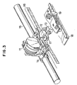
- the motor and associated parts are shown in oblique view in Figure 3, and include a carriage frame 14, a carriage shaft 15, a space rack 16, a motor gear 17, a baseplate 18 and a slider 19.
- the clock signal is next fed to a forward printer trigger generator 2, which outputs a print trigger signal at a given timing.
- This forward print trigger generator 2 can be any device that counts clock pulses and generates at trigger signal at every predetermined count. For example, it can be a combination of flip-flop gates and AND gates as shown in Figure 4.
- the print trigger signal is applied to a print-head driver 3 comprising resistors, capacitors, transistors, and other elements to carry out the printing operation.
- the clock signal is fed to a reverse print trigger generator 4, which outputs a print trigger signal at a given timing.
- the reverse print trigger generator can be any device capable of altering the lock count from the stopped position to the first trigger position by a correction value ⁇ t4 that is supplied from a correction section 5.
- the reverse print trigger generator 4 comprises a combination of the flip-flop gates and AND gates similar to that shown in Figure 4 and a decimating circuit connected at the input of the above combination.
- the decimating circuit decimates the pulses from the clock generator 1 at the start of lateral movement so that the number of pulses the clock generator 1 must produce before the first trigger is made is altered depending on the number of pulses decimated which in turn is dependent on the correction amount.
- FIG. 6 An example of the decimating circuit 20 is schematically shown in Figure 6. As illustrated it comprises a register 21 in which the correction amount (or a number of pulses corresponding to the correction amount) is fed from the correction section 5 and stored. A counter 22 counts the clock signal from the clock generator 1 and produces a low-level signal until the number of pulses fed from the clock generator reaches the value as stored in the register 21, after which an AND gate 23 is opened. The output of the AND gate is applied to the combination of flip-flop and AND gates similar to that shown in Figure 4.
- the correction value ⁇ t4 must conform to the sum of the amounts of misalignment due to various factors.
- Figure 1 assumes a situation where the misalignment are due to the following factors: ⁇ t1: the reverse printing misalignment, measured in seconds, caused by dimensional variations, for example by variations in the gap, which causes differences in the time taken for the wires to reach the platen. ⁇ t2: the misalignment, measured in seconds, caused by variations in print-head characteristics, for example by variations in the time required to release the wires, due to differences in attractive magnetic force. ⁇ t3: the misalignment, measured in seconds, caused by variations in circuit elements, for example variations in the values of resistors which cause variations in drive time. The sum ( ⁇ t1 + ⁇ t2 + ⁇ t3 ) is the misalignment that arises in the forward direction, measured in seconds.
- a correction amount of ⁇ t4 -( ⁇ t1 + ⁇ t2 + ⁇ t3) seconds should therefore be added by the correction section 5.
- the correction section 5 can be configured as shown in the block diagram in Figure 2.
- a switch 6 When a switch 6 is pressed correction amounts stored in a read-only memory 7 are read and printed one by one on a sheet which is then fed (line-fed) out so that the printed part can be seen by the operator immediately after the printing.
- another switch 8 is pressed to write the selected correction amount in a battery-back-up memory 10 (substituting any previously stored correction amount).
- Figure 7 shows a hardware configuration of the control system of the printer.
- ROM stores programs as well as a table of correction amounts and other fixed data that are used for control of the printer.
- RAM is backed up by a battery and stores the correction amount that has been considered most appropriate.
- the print-head driver, the space motor driver and a line-feed motor driver are connected via an I/O port.
- switches including SEL switch, TOF switch, FF switch and LF switch are also connected via an I/O port.
- the CPU operates under control of the programs stored in the ROM and in accordance with data derived from the switches as well as sensors, not shown, in various parts of the printers.
- Figure 8 shows operations of the CPU when various settings are made.
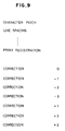
- Figure 9 shows an example of printouts that are made in the course of the setting procedure.
- the setting (or rewriting) of the correction amount is performed in part of a program that also governs setting of character pitch, line spacing, etc.
- the switches used for the settings are the ones that are also used for ( and they are primarily intended for) other purposes.
- TOF top of form
- SEL select
- next correction amount is printed.
- a test pattern such as a series of characters "H" are printed in one direction and then in the other. Comparison of the printed characters one above another will show any misalignment and desired correction.
- the correction amount is applied to the reverse print trigger generator to alter the number of clock pulses that must be applied before the first trigger signal is produced during backward travel of the print-head.
- the correction amount selected in this way and the clock signal from the clock generator 1 are fed to the reverse print trigger generator 4 to generate a trigger signal at a timing that will not give rise to misalignment.
- the memory 10 that holds the correction t4 applied to the reverse print trigger generator 4 is backed up by a battery 9, so the selected correction amount is retained even after power is switched off. It is not necessary to reset the correction amount each time power i s turned off and on.
- Figure 10 shows a situation where there is an additional factor that also causes misalignment, that is aging variation ⁇ t5, measured in seconds. This may for example be due to wear of mechanical parts.
- this invention provides a table of bidirectional printing misalignment correction amounts written in a read-only memory, which can be read out by a switch operation.
- a correction amount that is considered appropriate, another switch can be pressed to select this correction amount and write the selection correction amount into a rewritable battery-backed-up memory to correct the bidirectional printing alignment.
- This arrangement simplifies both the setting of the alignment correction amount during initial assembly and the resetting of the alignment correction amount if required due to aging changes after the printer is in the possession of the user. Since the correction amount is stored in a battery-backed-up memory, the selected correction amount is retained after power is switched off and remains in effect at all times. The correction amount need only apply to one direction of print head travel so that alignment with characters printed in the other direction of print travel can be achieved.
Landscapes
- Engineering & Computer Science (AREA)
- Human Computer Interaction (AREA)
- Manufacturing & Machinery (AREA)
- Physics & Mathematics (AREA)
- General Physics & Mathematics (AREA)
- Automation & Control Theory (AREA)
- Quality & Reliability (AREA)
- Character Spaces And Line Spaces In Printers (AREA)
- Dot-Matrix Printers And Others (AREA)
Claims (7)
- Procédé d'actionnement d'une imprimante matricielle série ayant une tête d'impression mobile de façon bi-directionnelle (11) comportant la mémorisation dans un dispositif de mémoire (7) d'un ensemble de valeurs de correction (△t₄) afin de corriger de façon bi-directionnelle l'alignement des positions d'impression, caractérisé par la lecture dans le dispositif de mémoire (7) et l'impression de manière successive des valeurs de correction (△t₄), l'actionnement d'un contacteur (8) lorsque une valeur de correction appropriée (△t₄) est imprimée afin d'écrire cette valeur de correction (△t₄) dans un dispositif de mémoire réinscriptible (10) qui possède une batterie (9) comme source d'alimentation de sauvegarde, et l'impression en utilisant la valeur de correction (△t₄) écrite dans le dispositif de mémoire (10).
- Procédé selon la revendication 1, comportant en outre la vérification que la valeur de correction écrite dans le dispositif de mémoire (10) est la valeur de correction appropriée (△t₄) en imprimant une ligne de caractères de test dans un sens et une ligne de caractères de test dans l'autre sens, et en comparant les deux lignes de caractères de test pour le défaut d'alignement.
- Procédé selon la revendication 1 ou la revendication 2, dans lequel l'impression comprend le réglage de la synchronisation de l'impression en fonction de la valeur de correction (△t₄).
- Procédé selon l'une quelconque des revendications 1 à 3, dans lequel le dispositif de mémoire réinscriptible (10) est une mémoire vive.
- Procédé selon l'une quelconque des revendications précédentes, dans lequel l'impression successive des valeurs de correction (△t₄) comprend l'impression des valeurs de correction (△t₄) de manière individuelle en réponse à l'actionnement d'un contacteur (6).
- Procédé selon l'une quelconque des revendications précédentes, comportant en outre l'actionnement d'un contacteur de commande d'alimentation tout en actionnant l'autre contacteur et ensuite l'actionnement d'un autre contacteur afin d'entrer dans un mode d'impression successive des valeurs de correction (△t₄) et d'écriture de la valeur de correction appropriée (△t₄) dans le dispositif de mémoire réinscriptible (10).
- Procédé selon l'une quelconque des revendications précédentes, dans lequel le dispositif de mémoire (7) est une mémoire morte.
Applications Claiming Priority (2)
| Application Number | Priority Date | Filing Date | Title |
|---|---|---|---|
| JP239218/86 | 1986-10-09 | ||
| JP61239218A JPH0784081B2 (ja) | 1986-10-09 | 1986-10-09 | シリアルドツトプリンタの往復印字アライメントの補正方法 |
Publications (2)
| Publication Number | Publication Date |
|---|---|
| EP0263688A1 EP0263688A1 (fr) | 1988-04-13 |
| EP0263688B1 true EP0263688B1 (fr) | 1991-08-07 |
Family
ID=17041502
Family Applications (1)
| Application Number | Title | Priority Date | Filing Date |
|---|---|---|---|
| EP87308872A Expired EP0263688B1 (fr) | 1986-10-09 | 1987-10-07 | Procédé pour corriger l'alignement d'impression d'une imprimante en série à matrice par points |
Country Status (4)
| Country | Link |
|---|---|
| US (1) | US4818129A (fr) |
| EP (1) | EP0263688B1 (fr) |
| JP (1) | JPH0784081B2 (fr) |
| DE (1) | DE3771991D1 (fr) |
Families Citing this family (22)
| Publication number | Priority date | Publication date | Assignee | Title |
|---|---|---|---|---|
| JPS6447556A (en) * | 1987-08-19 | 1989-02-22 | Brother Ind Ltd | Printer |
| JPH01218850A (ja) * | 1988-02-29 | 1989-09-01 | Toshiba Corp | プリンタ装置 |
| JPH02261678A (ja) * | 1989-03-31 | 1990-10-24 | Brother Ind Ltd | 往復印字の印字位置ずれ補正機能を有するプリンタ |
| US5258773A (en) * | 1990-02-02 | 1993-11-02 | Canon Kabushiki Kaisha | Serial recording apparatus for bidirectional recording |
| JP2941906B2 (ja) * | 1990-02-02 | 1999-08-30 | キヤノン株式会社 | シリアル記録装置 |
| JPH0490369A (ja) * | 1990-08-02 | 1992-03-24 | Canon Inc | プリンタ制御装置 |
| US5988784A (en) * | 1992-11-12 | 1999-11-23 | Canon Kabushiki Kaisha | Method and apparatus for recording information with corrected drive timing |
| US5617122A (en) * | 1992-12-10 | 1997-04-01 | Canon Kabushiki Kaisha | Recording apparatus and method for controlling recording head driving timing |
| KR0123531B1 (ko) * | 1993-02-26 | 1997-11-24 | 김광호 | 시리얼 프린터의 캐리지 최적 제어방법 |
| US5534895A (en) * | 1994-06-30 | 1996-07-09 | Xerox Corporation | Electronic auto-correction of misaligned segmented printbars |
| US5975776A (en) * | 1995-06-06 | 1999-11-02 | Axiohm Transaction Solutions, Inc. | Dot matrix print head with unitary armature assembly and method of operation thereof |
| US6431775B1 (en) * | 1995-09-12 | 2002-08-13 | Industrial Technology Research Institute | Automatic print cartridge alignment system |
| JPH10193658A (ja) * | 1996-11-14 | 1998-07-28 | Sanyo Electric Co Ltd | 分割シール記録紙を用いる印写方法および印写装置 |
| EP0938977B1 (fr) * | 1997-09-02 | 2006-06-07 | Seiko Epson Corporation | Imprimante pour impression bidirectionnelle et procede de reglage de la position d'impression |
| US5956055A (en) * | 1997-10-10 | 1999-09-21 | Lexmark International, Inc. | Method of compensating for skewed printing in an ink jet printer |
| JP3604891B2 (ja) * | 1997-12-24 | 2004-12-22 | キヤノン株式会社 | 補正方法及び記録装置 |
| JP2001277597A (ja) * | 2000-04-03 | 2001-10-09 | Nec Data Terminal Ltd | ドットラインプリンタの印字位置調整方法および装置 |
| KR20020026075A (ko) * | 2000-09-30 | 2002-04-06 | 윤종용 | 잉크젯 프린터의 어레이 헤드에 장착된 칩들간의 오정렬에의한 인쇄 오차 보정 방법 |
| US6655777B2 (en) | 2001-07-18 | 2003-12-02 | Lexmark International, Inc. | Automatic horizontal and vertical head-to-head alignment method and sensor for an ink jet printer |
| US6616261B2 (en) | 2001-07-18 | 2003-09-09 | Lexmark International, Inc. | Automatic bi-directional alignment method and sensor for an ink jet printer |
| US6938975B2 (en) * | 2003-08-25 | 2005-09-06 | Lexmark International, Inc. | Method of reducing printing defects in an ink jet printer |
| US7140793B2 (en) * | 2004-06-18 | 2006-11-28 | Lexmark International, Inc. | Imaging apparatus having a carrier support and drive arrangement |
Family Cites Families (12)
| Publication number | Priority date | Publication date | Assignee | Title |
|---|---|---|---|---|
| JPS5517990B2 (fr) * | 1974-08-12 | 1980-05-15 | ||
| US4210404A (en) * | 1977-11-01 | 1980-07-01 | General Electric Company | Printhead compensation arrangement for printer |
| JPS5729478A (en) * | 1980-07-29 | 1982-02-17 | Hitachi Ltd | Controlling system of printing position in printer |
| JPS5745070A (en) * | 1980-08-31 | 1982-03-13 | Fujitsu Ltd | Correction of deviated printing for normal and reverce direction in dot type serial printer |
| US4460968A (en) * | 1981-10-16 | 1984-07-17 | International Business Machines Corporation | Print head motor control with stop distance compensation |
| JPS58163685A (ja) * | 1982-03-24 | 1983-09-28 | Fujitsu Ltd | スペ−ス制御方式 |
| US4517503A (en) * | 1983-09-27 | 1985-05-14 | Mechatron Systems, Inc. | Method and apparatus for normalizing the speed of an element positionable by a servomechanism |
| JPS615953A (ja) * | 1984-06-07 | 1986-01-11 | Fujitsu Ltd | 印字位置の微少補正方法 |
| JPH0686133B2 (ja) * | 1984-06-22 | 1994-11-02 | 富士通株式会社 | シリアルプリンタ |
| JPH077391B2 (ja) * | 1985-01-30 | 1995-01-30 | シャープ株式会社 | 文書処理装置 |
| JPS61147434U (fr) * | 1985-03-01 | 1986-09-11 | ||
| JPH038448Y2 (fr) * | 1985-03-29 | 1991-03-01 |
-
1986
- 1986-10-09 JP JP61239218A patent/JPH0784081B2/ja not_active Expired - Lifetime
-
1987
- 1987-10-02 US US07/103,824 patent/US4818129A/en not_active Expired - Lifetime
- 1987-10-07 DE DE8787308872T patent/DE3771991D1/de not_active Expired - Lifetime
- 1987-10-07 EP EP87308872A patent/EP0263688B1/fr not_active Expired
Also Published As
| Publication number | Publication date |
|---|---|
| JPS6394856A (ja) | 1988-04-25 |
| JPH0784081B2 (ja) | 1995-09-13 |
| EP0263688A1 (fr) | 1988-04-13 |
| DE3771991D1 (de) | 1991-09-12 |
| US4818129A (en) | 1989-04-04 |
Similar Documents
| Publication | Publication Date | Title |
|---|---|---|
| EP0263688B1 (fr) | Procédé pour corriger l'alignement d'impression d'une imprimante en série à matrice par points | |
| US4311399A (en) | Method and apparatus for setting and varying margins and line spacing on data printers | |
| US5069556A (en) | Method for correcting drift of printing position and printing apparatus for practising the same | |
| US4403301A (en) | Word processor adapted for filling in blanks on preprinted forms | |
| EP0943447B1 (fr) | Procédé et appareil d'impression | |
| US4411540A (en) | Printing apparatus | |
| US4429318A (en) | Thermal transfer printer | |
| EP0291099A1 (fr) | Appareil pour marquer la position d'origine d'un membre mobile | |
| US4780012A (en) | Paper feeding control system of automatic paper feeder | |
| US4688956A (en) | Carriage feed control method for bold and shadow printing | |
| CA1130463A (fr) | Imprimante de caracteres par points a commande de vitesse variable | |
| GB2197105A (en) | Serial printer | |
| US5880749A (en) | Recording method and apparatus in which use of recording heads is equalized | |
| US5028157A (en) | Printer having an erasing mechanism | |
| JPS612586A (ja) | タイプライタまたは類似の機械のプリント機構を初期状態にリセツトする方法 | |
| GB2233175A (en) | Printer and stepping motor control | |
| US4863295A (en) | Printer platen motor controller | |
| EP0199185B1 (fr) | Dispositif d'impression | |
| GB2208952A (en) | Bidirectional printers | |
| JPS6274664A (ja) | プリンタの印字開始位置調整装置 | |
| EP1093413B1 (fr) | Dispositif electronique pour commander des elements mobiles dans un equipement de traitement de texte et/ou d'images | |
| EP0186465A2 (fr) | Imprimante | |
| GB2309938A (en) | Tape printing apparatus | |
| JPS6261437B2 (fr) | ||
| EP0345084B1 (fr) | Imprimante à matrice de points comportant deux ensembles d'éléments générateurs de points |
Legal Events
| Date | Code | Title | Description |
|---|---|---|---|
| PUAI | Public reference made under article 153(3) epc to a published international application that has entered the european phase |
Free format text: ORIGINAL CODE: 0009012 |
|
| AK | Designated contracting states |
Kind code of ref document: A1 Designated state(s): DE FR GB |
|
| 17P | Request for examination filed |
Effective date: 19880723 |
|
| 17Q | First examination report despatched |
Effective date: 19891120 |
|
| GRAA | (expected) grant |
Free format text: ORIGINAL CODE: 0009210 |
|
| AK | Designated contracting states |
Kind code of ref document: B1 Designated state(s): DE FR GB |
|
| ET | Fr: translation filed | ||
| REF | Corresponds to: |
Ref document number: 3771991 Country of ref document: DE Date of ref document: 19910912 |
|
| PLBE | No opposition filed within time limit |
Free format text: ORIGINAL CODE: 0009261 |
|
| STAA | Information on the status of an ep patent application or granted ep patent |
Free format text: STATUS: NO OPPOSITION FILED WITHIN TIME LIMIT |
|
| 26N | No opposition filed | ||
| REG | Reference to a national code |
Ref country code: GB Ref legal event code: IF02 |
|
| PGFP | Annual fee paid to national office [announced via postgrant information from national office to epo] |
Ref country code: GB Payment date: 20061004 Year of fee payment: 20 |
|
| PGFP | Annual fee paid to national office [announced via postgrant information from national office to epo] |
Ref country code: DE Payment date: 20061005 Year of fee payment: 20 |
|
| REG | Reference to a national code |
Ref country code: GB Ref legal event code: PE20 |
|
| PG25 | Lapsed in a contracting state [announced via postgrant information from national office to epo] |
Ref country code: GB Free format text: LAPSE BECAUSE OF EXPIRATION OF PROTECTION Effective date: 20071006 |
|
| PGFP | Annual fee paid to national office [announced via postgrant information from national office to epo] |
Ref country code: FR Payment date: 20061010 Year of fee payment: 20 |