EP0263009A1 - Connecting piece between the beam and upright of a rack - Google Patents
Connecting piece between the beam and upright of a rack Download PDFInfo
- Publication number
- EP0263009A1 EP0263009A1 EP87402038A EP87402038A EP0263009A1 EP 0263009 A1 EP0263009 A1 EP 0263009A1 EP 87402038 A EP87402038 A EP 87402038A EP 87402038 A EP87402038 A EP 87402038A EP 0263009 A1 EP0263009 A1 EP 0263009A1
- Authority
- EP
- European Patent Office
- Prior art keywords
- hooks
- connecting piece
- upright
- cutouts
- studs
- Prior art date
- Legal status (The legal status is an assumption and is not a legal conclusion. Google has not performed a legal analysis and makes no representation as to the accuracy of the status listed.)
- Withdrawn
Links
Images


Classifications
-
- A—HUMAN NECESSITIES
- A47—FURNITURE; DOMESTIC ARTICLES OR APPLIANCES; COFFEE MILLS; SPICE MILLS; SUCTION CLEANERS IN GENERAL
- A47B—TABLES; DESKS; OFFICE FURNITURE; CABINETS; DRAWERS; GENERAL DETAILS OF FURNITURE
- A47B57/00—Cabinets, racks or shelf units, characterised by features for adjusting shelves or partitions
- A47B57/30—Cabinets, racks or shelf units, characterised by features for adjusting shelves or partitions with means for adjusting the height of detachable shelf supports
- A47B57/40—Cabinets, racks or shelf units, characterised by features for adjusting shelves or partitions with means for adjusting the height of detachable shelf supports consisting of hooks coacting with openings
- A47B57/402—Hooks attached to a member embracing at least two sides of an upright, e.g. an angle bracket
-
- A—HUMAN NECESSITIES
- A47—FURNITURE; DOMESTIC ARTICLES OR APPLIANCES; COFFEE MILLS; SPICE MILLS; SUCTION CLEANERS IN GENERAL
- A47B—TABLES; DESKS; OFFICE FURNITURE; CABINETS; DRAWERS; GENERAL DETAILS OF FURNITURE
- A47B57/00—Cabinets, racks or shelf units, characterised by features for adjusting shelves or partitions
- A47B57/30—Cabinets, racks or shelf units, characterised by features for adjusting shelves or partitions with means for adjusting the height of detachable shelf supports
- A47B57/40—Cabinets, racks or shelf units, characterised by features for adjusting shelves or partitions with means for adjusting the height of detachable shelf supports consisting of hooks coacting with openings
Landscapes
- Assembled Shelves (AREA)
- Packaging Of Annular Or Rod-Shaped Articles, Wearing Apparel, Cassettes, Or The Like (AREA)
Abstract
Description
La présente invention concerne une pièce destinée à fixer une lisse d'un casier, tel qu'un casier de stockage, sur un montant vertical, ladite pièce étant fixée sur l'extrémité de la lisse et munie de crochets en saillie qui s'engagent dans des découpes du montant précité, ces découpes étant alignées verticalement selon un pas d'écartement régulier.The present invention relates to a part intended to fix a heald of a rack, such as a storage rack, on a vertical upright, said piece being fixed on the end of the heald and provided with projecting hooks which engage in cutouts of the aforementioned amount, these cutouts being aligned vertically at a regular spacing pitch.
Ces crochets ou analogues doivent remplir un certain nombre de fonctions;tout d'abord ils doivent assurer un positionnement le plus précis possible des lisses, en particulier dans le sens de la largeur du casier c'est-à-dire de la longueur de la lisse; du point du vue de la résistance des matériaux, les crochets ou analogues doivent réaliser la reprise des efforts tranchants et des couples qui s'exercent sur les lisses; enfin, ces crochets doivent assurer une protection contre les chocs que peuvent subir les lisses, en particulier lorsqu'il s'agit de casiers de stockage recevant des palettes, les lisses subissent des chocs transversaux exercés par les palettes ou les chariots porte-palette lors des opérations de chargement ou de déchargement. Pour résister à ces chocs transversaux, les dispositifs d'accrochage doivent empêcher les lisses de se décrocher lors de ces chocs qui peuvent être brutaux.These hooks or the like must fulfill a certain number of functions; first of all they must ensure the most precise positioning possible of the beams, in particular in the direction of the width of the rack, that is to say the length of the smooth; from the point of view of the resistance of the materials, the hooks or the like must realize the resumption of the shearing forces and of the torques which are exerted on the healds; finally, these hooks must provide protection against the shocks that the beams can undergo, in particular in the case of storage racks receiving pallets, the beams undergo transverse shocks exerted by the pallets or the pallet-carrying carriages during loading or unloading operations. To resist these transverse shocks, the hooking devices must prevent the beams from falling off during these shocks which can be brutal.
Dans les pièces d'assemblage de type connu, ces trois fonctions sont réalisées par un seul type d'éléments d'accrochage et il n'est pas possible de réaliser les trois fonctions ci-dessus de manière satisfaisante sans surdimensionner les éléments d'accrochage ou sans prévoir un nombre important d'éléments d'accrochage par pièce d'assemblage. Par conséquent, le coût de fabrication de telles pièces d'assemblage est trop élevé et du plus, leur mise en place est parfois malaisée compte-tenu du nombre important de crochets.In assembly parts of known type, these three functions are performed by a single type of fastening elements and it is not possible to perform the above three functions satisfactorily without oversizing the fastening elements or without providing for a large number of fastening elements per assembly part. Consequently, the cost of manufacturing such assembly parts is too high and moreover, their installation is sometimes difficult given the large number of hooks.
On connait par ailleurs d'après la demande de brevet français 2398 909 une pièce d'assemblage dans laquelle les éléments d'accrochage sur le montant vertical sont constitués chacun par la combinaison d'un crochet et d'un bossage qui s'engagent tous les deux dans la même découpe du montant vertical. Ce dispositif connu permet de répartir sur le crochet et le bossage les différentes fonctions à réaliser par la pièce d'assemblage. Cependant, le nombre de crochets et de bossages étant nécessairement égal, on est généralement amené à prévoir un nombre trop important d'un de ces éléments, en général les crochets. Il en résulte un surdimensionnent de la pièce d'assemblage pour obtenir une résistance mécanique suffisante. Par ailleurs, les découpes ont des dimensions importantes, en particulier dans le sens de la hauteur, ce qui d'une part affaiblit la résistance mécanique du montant et, d'autre part, limite la possibilité de réduire le pas d'écartement des découpes, pas qui détermine la précision de montage en hauteur des lisses de casier. Enfin, du fait que le nombre des crochets est généralement trop important, la mise en place de cette pièce d'assemblage connu nécessite un positionnement prélable précis avant l'engagement des crochets et des bossages dans les découpes.We also know from French patent application 2398 909 an assembly part in which the hooking elements on the vertical upright are each formed by the combination of a hook and a boss which all engage both in the same cutout of the vertical upright. This known device makes it possible to distribute over the hook and the boss the various functions to be performed by the assembly part. However, the number of hooks and bosses being necessarily equal, it is generally necessary to provide an excessive number of one of these elements, in general the hooks. This results in an oversize of the assembly part to obtain sufficient mechanical strength. Furthermore, the cutouts have large dimensions, in particular in the height direction, which on the one hand weakens the mechanical resistance of the upright and, on the other hand, limits the possibility of reducing the spacing pitch of the cutouts , step which determines the precision of assembly in height of the rails of rack. Finally, because the number of hooks is generally too large, the installation of this known assembly part requires precise prior positioning before the hooks and bosses engage in the cutouts.
La présente invention a pour objet une pièce d'assemblage qui permet d'obtenir les trois fonctions qui ont été citées ci-dessus de manière satisfaisante pour chacune d'entre elles tout en limitant au maximum les frais d'usinage ; par ailleurs, la pièce d'assemblage selon l'invention est facile à mettre en place.The subject of the present invention is an assembly part which makes it possible to obtain the three functions which have been mentioned above in a satisfactory manner for each of them while minimizing the machining costs; moreover, the assembly part according to the invention is easy to install.
Cette pièce d'assemblage est notamment remarquable en ce que les crochets et les plots sont séparés les uns des autres et répartis de manière non nécessairement alternée sur ladite pièce d'assemblage, en en ce que chaque plot s'engage dans une découpe séparée et en ce que le pas d'écartement entre un crochet et le crochet ou plot voisin est égal au pas d'écartement des découpes du montant ou à un multiple de celui-ci.This assembly part is notably remarkable in that the hooks and the studs are separated from each other and distributed in a manner that is not necessarily alternated on said assembly piece, in that each stud engages in a separate cutout and in that the spacing pitch between a hook and the neighboring hook or stud is equal to the spacing pitch of the cutouts of the upright or to a multiple thereof.
De cette mainière on dissoci e les trois fonctions qui ont été énumérées ci-dessus, les plots tronconiques réalisent par effet de cône Morse le positionnement précis des lisses ainsi que la reprise des contraintes mécaniques constituées par les efforts tranchants et les coups s'exercant sur les lisses ; la sécurité contre le coups transversaux de chariots ou de palettes est réalisée par les crochets qui ne sont conçus et dimensionés que pour cette fonction.This three ways dissociate the three functions which have been listed above, the frustoconical studs realize by Morse cone effect the precise positioning of the beams as well as the resumption of the mechanical stresses constituted by the cutting forces and the blows exerted on the smooth; security against the transverse blows of trolleys or pallets is carried out by the hooks which are designed and sized only for this function.
Le nombre et la disposition des crochets et des plots peut être choisie de manière arbitraire en fonction par exemple de la charge prévue pour le casier. On peut donc réaliser ces trois fonctions sans aucun surdimentsionnement.The number and the arrangement of the hooks and the studs can be chosen arbitrarily depending for example on the load provided for the rack. We can therefore perform these three functions without any oversizing.
Les plots présentant un encombrement réduit par rapport aux crochets, il est possible de réduire le pas d'écartement des découpes sur le montant, ce pas d'écaretement étant par exemple de 5cm ; de cette manière, le nombre et le répartition des crochets et des plots peuvent encore être mieux adaptés à leur fonction respective.The studs having a reduced size compared to the hooks, it is possible to reduce the spacing of the cutouts on the upright, this spacing pitch being for example 5cm; in this way, the number and distribution of the hooks and the studs can be further adapted to their respective function.
Du fait que chaque plot et chaque crochet s'engagent dans une découpe séparée et du fait que le nombre de crochets peut être réduit au minimum pour éviter les décrochages dans le cas de coups transversaux, la mise en place de la pièce d'assemblage selon l'invention ne nécessite pas un positionnement préalable précis et elle est donc facile à réaliser.Because each stud and each hook engage in a separate cut and the fact that the number of hooks can be reduced to a minimum to avoid stalling in the case of transverse strikes, the installation of the assembly piece according to the invention does not require precise prior positioning and is therefore easy to carry out.
Avantageusement, les plots sont réalisés dans les pièces d'assemblage par une opération d'estampage ; ce procédé est plus avantageux que le procédé d'emboutissage qui était utilisé jusqu'à maintenant pour la réalisation de tels plots, car dans le procédé d'estampage, le plot fait saillie de la pièce tout en restant solidaire sur toutes ses faces de la paroi dans laquelle il a été réalisé.Advantageously, the studs are produced in the assembly parts by a stamping operation; this process is more advantageous than the stamping process which was used until now for the production of such studs, because in the stamping process, the stud protrudes from the part while remaining integral on all its faces with the wall in which it was made.
D'autres caractéristiques et avantages de l'invention ressortiront de la description qui suit ainsi que des dessins ci-annexés sur lesquels :- la Fig. 1 est une vue en perspective représentant un montant et une pièce d'assemblage conforme à la présente invention ;
- la Fig. 2 représente en perspective un autre mode de réalisation d'une pièce d'assemblage conforme à l'invention ;
- la Fig. 3 est une vue partielle de face de la pièce d'assemblage de la figure 2 ;
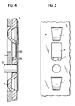
- la Fig. 4 représente en coupe une pièce d'assemblage fixée sur le montant et munie d'un dispositif de verrouillage ;
- la Fig. 5 est une vue en coupe d'un plot ;
- la Fig. 6 est une vue de face d'un plot ;
- la Fig. 7 est une vue de détail en coupe d'un trou servant à la fixation du dispositif de verrouillage, et
- la Fig. 8 est une vue de profil d'un crochet.
Other characteristics and advantages of the invention will emerge from the description which follows as well as from the appended drawings in which: - FIG. 1 is a perspective view showing an upright and an assembly part according to the present invention;
- Fig. 2 shows in perspective another embodiment of an assembly part according to the invention;
- Fig. 3 is a partial front view of the assembly part of FIG. 2;
- Fig. 4 shows in section an assembly part fixed to the upright and provided with a locking device;
- Fig. 5 is a sectional view of a stud;
- Fig. 6 is a front view of a stud;
- Fig. 7 is a detailed view in section of a hole used for fixing the locking device, and
- Fig. 8 is a side view of a hook.
On voit sur la figure 1 un montant vertical 1 d'un casier de stockage sur lequel viennent se fixer des lisses horizontales transversales. Ces lisses comportent à leur extrémité une pièce d'essemblage 2 qui est fixée par exemple par soudure sur l'extrémité de la lisse. Dans l'exemple représenté, cette pièce d'assemblage est constituée en profilé en équerre qui représente une première face 3 qui est fixée sur l'extrémité de la lisse et une deuxième face 4 sur laquelle sont prévus les éléments d'accrochage.We see in Figure 1 a vertical upright 1 of a locker storage on which are fixed horizontal cross beams. These heddles have at their end an
Le montant 1 comporte deux séries de découpe 5 qui sont alignées selon deux rangées verticales avec un pas d'écartement régulier, chaque rangée recevant la pièce d'assemblage d'une lisse venant se fixer sur le montent, les deux lisses étant fixées de part et d'autre du montant 1 pratiquement en alignement avec ce dernier.The upright 1 comprises two series of cutouts 5 which are aligned in two vertical rows with a regular spacing pitch, each row receiving the assembly part of a heald coming to be fixed on the mount, the two healds being fixed on the side and the other of the upright 1 practically in alignment with the latter.
Conformément à l'invention, les éléments d'assemblage de la pièce 2, sont constitués, d'une part des crochets 6 et d'autre part, des plots en saillie 7 qui s'engagent chacun dans des découpes 5 et qui sont donc disposés en alignement vertical. Le nombre et la répartition respective des crochets 6 et des plots 7 sur une pièce d'assemblage 2 est déterminé en fonction des caractéristiques du casier réalisé à l'aide des lisses et des montants et l'écartement entre deux éléments d'accrochage voisins, crochet et/ou plot est égal au pas d'écartement des découpes 5 ou un multiple de ce dernier.According to the invention, the assembly elements of the
Conformément à l'invention, les crochets 6 sont conçus de manière à ne réaliser que la sécurité contre les coups et chocs transversaux sur le casier, en particulier sur les lisses. Les plots 7 qui sont de forme troncônique avec rétrécissement vers le bas servent d'une part au positionnement des lisses sur les montants 1 par effet de cône Morse en coopérant avec les découpes 5 qui sont également de forme tronconique. D'autre part les plots 7 réalisent la reprise des efforts tranchants et des couples qui s'exercent sur les lisses.According to the invention, the
Comme on peut le voir en particulier sur les figures 5 et 6, les plots 7 sont réalisés par une opération mécanique d'estampage, ce qui, par rapport à l'opération d'emboutissage classique, présente l'avantage qu'il n'y a pas de déchirure de la matière et que les plots resentent solidaire de la face 4 de la pièce 2 sur toute leur périphérie. Ceci accroît les possibilité de reprise des efforts mécaniques exercés sur les lisses.As can be seen in particular in FIGS. 5 and 6, the
Selon un mode de réalisation de l'invention, ces plots ont une hauteur d'environ 13 mm, une largeur d'environ 12 mm ils font saillie de la face 4 d'environ 4 mm. Leur conicité est telle que la descente du plot 7 dans la découpe 5 après l'engagement du crochet 6 dans les découpes 5 est limité à 2 mm. Dans cette position les cônes pénètrent jusqu'au fond de la découpe 5 de sorte que le contact entre la pièce d'assemblage 2 et le montant 1 s'effectue par les faces latérales des plots et également par leur arête inférieure si bien que la reprise des efforts tranchant est réalisée sur trois faces du plot 7, ce qui en améliore les performances.According to one embodiment of the invention, these studs have a height of approximately 13 mm, a width of approximately 12 mm, they project from the
Les crochets 6 sont réalisés par découpage dans la face 4 de la pièce 2 avec un pliage ultérieur. Selon un premier mode de réalisation qui est représenté sur la figure 1 on réalise une encoche ouverte dans la face 4 avec une découpe appropriée au profil du crochet puis on replie l'élément obtenu par l'operation de découpe vers l'intérieur de la pièce d'assemblage 2, c'est-à-dire vers l'arête 11 de la pièce d'assemblage 2.The
Selon un deuxième mode de réalisation qui est représenté sur la figure 2, on effectue une découpe dans une encoche 12 non ouverte de la face 4 et on replie l'élément obtenu par l'opération de découpe vers l'extérieur, c'est-à-dire du côté opposé à l'arête 11 de manière à obtenir le crochet 13.According to a second embodiment which is shown in FIG. 2, a cut is made in an
Comme on peut le voir sur la figure 8 qui est une vue de profil d'un crochet, l'arête 14 du crochet 6 qui fait face à la face 4 de la pièce d'assemblage 2 présente un certaine inclinaison, par exemple de l'ordre de 10° de manière à faciliter la mise en place du crochet 6 dans la découpe 5. Lorsque la pièce d'assemblage 2 est mise en place sur le montant 1, il y a peu ou pas de contact entre l'arête 14 du crochet 6 et la face interne du montant 1, ce contact étant de toute façon pratiquement ponctuel. En effet, du fait que le crochet n'est utilisé que pour assurer la sécurité contre les chocs transversaux, il n'est pas nécessaire qu'il y ait un contact important entre le crochet et le montant 1.As can be seen in FIG. 8 which is a side view of a hook, the
Du fait du rôle réduit joué par les crochets, leur nombre et leur dimension peuvent être réduits pour chaque pièce d'assemblage; ainsi dans un exemple de réalisation, la hauteur des crochets est d'environ 21 mm et on prévoit pour chaque pièce d'assemblage deux crochets et quatre plots. Du fait de la dimension réduite des crochets, on peut réduire notablement le pas d'écartement des découpes 5 du montant 1; ce pas peut par exemple être égal à 500mm, ce qui permet de réaliser des pièces d'assemblage qui sont parfaitement adaptées à leur condition d'utilisation par le nombre et la répartition des crochets et des plots.Due to the reduced role played by the hooks, their number and size can be reduced for each assembly part; thus in an exemplary embodiment, the height of the hooks is approximately 21 mm and two hooks and four studs are provided for each assembly part. Due to the reduced size of the hooks, the spacing of the cutouts 5 of the upright 1 can be significantly reduced; this pitch can for example be equal to 500mm, which makes it possible to produce assembly parts which are perfectly adapted to their condition of use by the number and distribution of the hooks and the studs.
On voit sur les figures 1 et 4 un dispositif de verrouillage 21 de type connu qui est destiné à empêcher le décrochage de la pièce d'assemblage 2. Ce dispositif de verrouillage comporte une languette intérieure so uple 22 et un téton 23. Pour la mise en place de ce dispositif de verrouillage, on engage la languette souple 22 dans une ouverture spéciale 24 prévue dans la face 4 de la pièce 2 et on pousse le dispositif de verrouillage 21 vers le base jusqu'à ce que le téton 23 vienne s'engager dans un trou 25 également prévu dans ladite face 4. L'extrémité 26 de la languette 22 est contrecoudée et elle vient s'engager dans un évidement 27 aménagé dans le bord inférieur du trou 24 comme on peut le voir sur les figures 2, 3, 4 et 7. Ce dispositif de verrouillage peut également être constitué par une goupille.We see in Figures 1 and 4 a
On voit que l'invention permet de dissocier les différentes fonctions réalisées par la pièce d'assemblage et, de ce fait de limiter son dimensionnement et par suite son prix de revient. Du fait de la possibilité d'utiliser un pas réduit pour les découpes du montant, on peut parfaitement adapter la pièce d'assemblage au contrainte qu'elle doit subir et absorber.It can be seen that the invention makes it possible to dissociate the different functions performed by the assembly part and, therefore, to limit its dimensioning and consequently its cost price. Because of the possibility of using a reduced pitch for the cut-outs of the upright, it is perfectly possible to adapt the assembly part to the stress which it must undergo and absorb.
Claims (6)
Applications Claiming Priority (2)
| Application Number | Priority Date | Filing Date | Title |
|---|---|---|---|
| FR8612845 | 1986-09-15 | ||
| FR8612845A FR2603783B1 (en) | 1986-09-15 | 1986-09-15 | ASSEMBLY PART OF A RACK OF A LOCKER ON AN UPRIGHT |
Publications (1)
| Publication Number | Publication Date |
|---|---|
| EP0263009A1 true EP0263009A1 (en) | 1988-04-06 |
Family
ID=9338930
Family Applications (1)
| Application Number | Title | Priority Date | Filing Date |
|---|---|---|---|
| EP87402038A Withdrawn EP0263009A1 (en) | 1986-09-15 | 1987-09-14 | Connecting piece between the beam and upright of a rack |
Country Status (3)
| Country | Link |
|---|---|
| EP (1) | EP0263009A1 (en) |
| FR (1) | FR2603783B1 (en) |
| PT (1) | PT85723A (en) |
Cited By (7)
| Publication number | Priority date | Publication date | Assignee | Title |
|---|---|---|---|---|
| WO1995030358A1 (en) * | 1994-05-06 | 1995-11-16 | Dexion Holding Gmbh | Locking element for a plug-in stand or rack |
| GB2313293A (en) * | 1996-05-22 | 1997-11-26 | Fredrick Usher | Hook and slot connector with locking device |
| GB2324709A (en) * | 1997-05-02 | 1998-11-04 | Dexion Group Plc | Beam connector for racking systems |
| EP1145938A1 (en) * | 2000-04-11 | 2001-10-17 | Scolastica Frizzo | Stanchion for erecting the body of truck trailers and semitrailers |
| EP2184221A1 (en) * | 2008-11-10 | 2010-05-12 | F. HESTERBERG & SÖHNE GmbH & Co. KG | Bar holder for commercial vehicle trailers |
| EP2993112A1 (en) * | 2014-09-05 | 2016-03-09 | Helmut Fliegl | Post system for a roof structure of a trailer or commercial vehicle |
| US20230309691A1 (en) * | 2019-02-15 | 2023-10-05 | Clairson, Inc. | Storage system and hardware |
Citations (4)
| Publication number | Priority date | Publication date | Assignee | Title |
|---|---|---|---|---|
| CH479278A (en) * | 1969-01-11 | 1969-10-15 | Ledergerber Hugo | Frame with height-adjustable shelves |
| GB2001727A (en) * | 1977-07-28 | 1979-02-07 | Dexion Comino Int Ltd | Connection means for framework structures |
| GB2067706A (en) * | 1980-01-18 | 1981-07-30 | Santry Eng Co Ltd | Pallet rack joint |
| GB2069321A (en) * | 1980-02-14 | 1981-08-26 | Metalrax Ltd | Frameworks |
-
1986
- 1986-09-15 FR FR8612845A patent/FR2603783B1/en not_active Expired - Fee Related
-
1987
- 1987-09-14 EP EP87402038A patent/EP0263009A1/en not_active Withdrawn
- 1987-09-15 PT PT8572387A patent/PT85723A/en not_active Application Discontinuation
Patent Citations (4)
| Publication number | Priority date | Publication date | Assignee | Title |
|---|---|---|---|---|
| CH479278A (en) * | 1969-01-11 | 1969-10-15 | Ledergerber Hugo | Frame with height-adjustable shelves |
| GB2001727A (en) * | 1977-07-28 | 1979-02-07 | Dexion Comino Int Ltd | Connection means for framework structures |
| GB2067706A (en) * | 1980-01-18 | 1981-07-30 | Santry Eng Co Ltd | Pallet rack joint |
| GB2069321A (en) * | 1980-02-14 | 1981-08-26 | Metalrax Ltd | Frameworks |
Cited By (11)
| Publication number | Priority date | Publication date | Assignee | Title |
|---|---|---|---|---|
| WO1995030358A1 (en) * | 1994-05-06 | 1995-11-16 | Dexion Holding Gmbh | Locking element for a plug-in stand or rack |
| GB2313293A (en) * | 1996-05-22 | 1997-11-26 | Fredrick Usher | Hook and slot connector with locking device |
| GB2313293B (en) * | 1996-05-22 | 2000-11-08 | Fredrick Usher | A connector |
| GB2324709A (en) * | 1997-05-02 | 1998-11-04 | Dexion Group Plc | Beam connector for racking systems |
| WO1998049923A1 (en) * | 1997-05-02 | 1998-11-12 | Dexion Group Limited | Beam end connector |
| GB2324709B (en) * | 1997-05-02 | 2001-12-05 | Dexion Group Plc | Beam end connector |
| EP1145938A1 (en) * | 2000-04-11 | 2001-10-17 | Scolastica Frizzo | Stanchion for erecting the body of truck trailers and semitrailers |
| EP2184221A1 (en) * | 2008-11-10 | 2010-05-12 | F. HESTERBERG & SÖHNE GmbH & Co. KG | Bar holder for commercial vehicle trailers |
| EP2993112A1 (en) * | 2014-09-05 | 2016-03-09 | Helmut Fliegl | Post system for a roof structure of a trailer or commercial vehicle |
| EP2993112B1 (en) | 2014-09-05 | 2019-01-09 | Helmut Fliegl | Post system for a roof structure of a trailer or commercial vehicle |
| US20230309691A1 (en) * | 2019-02-15 | 2023-10-05 | Clairson, Inc. | Storage system and hardware |
Also Published As
| Publication number | Publication date |
|---|---|
| PT85723A (en) | 1988-10-14 |
| FR2603783A1 (en) | 1988-03-18 |
| FR2603783B1 (en) | 1990-09-21 |
Similar Documents
| Publication | Publication Date | Title |
|---|---|---|
| WO2006059043A1 (en) | Assembly for coupling wear parts to support tools for heavy-construction machinery | |
| CH624728A5 (en) | ||
| EP0263009A1 (en) | Connecting piece between the beam and upright of a rack | |
| WO1997036520A1 (en) | Chair consisting of interlocking elements | |
| FR2486470A1 (en) | CARGO HOLDING DEVICE, IN PARTICULAR FOR WOOD FLOOR TRANSPORT VEHICLES | |
| FR2667768A1 (en) | DEVICE FOR FIXING ACCESSORIES TO WALLS. | |
| FR2919763A1 (en) | DEVICE FOR CONNECTING TWO CABINETS FOR ELECTRICAL APPLIANCES | |
| FR2517240A1 (en) | DEVICE FOR FASTENING TOOL ROLLER | |
| EP1967624B1 (en) | Loom reed, loom comprising such a reed and method of manufacturing such a reed | |
| EP0156686B2 (en) | Supporting device for a nuclear fuel assembly in a reactor | |
| EP0736457A1 (en) | Container, in particular box-pallet | |
| FR2785880A1 (en) | CONTAINER FOR THE TRANSPORT AND / OR STORAGE OF A PLURALITY OF LONGIFORM PARTS, ESPECIALLY BUMPERS | |
| EP2444586B1 (en) | Removable Ladder System for Housing and Storage Modul, and Ladder therefor | |
| FR2661208A1 (en) | Connection with key for scaffolding | |
| EP0524896B1 (en) | Locking arrangement for assembling scaffolding | |
| FR2495884A1 (en) | Frame for rigidly holding printed circuit cards in prodn. treatments - has parallel cross-members, within rigid frame, each having mutually facing rims on which boards are supported in soldering tanks | |
| EP0412894B1 (en) | Arrangement of structural elements for the construction of assemblies and assemblies thus obtained | |
| WO2019073287A1 (en) | Seat having an underframe clip-fastenable to the seat cushion | |
| FR2690324A1 (en) | Foldable shoe rack. | |
| FR2818596A1 (en) | Vehicle seat has rigid frame covered in upholstery, sides of back rest frame having grip bars mounted on them using plates on their ends with hooks which fit through slots in sides and are then fixed in place by screws or rivets | |
| FR2548250A1 (en) | Scaffolding equipment with claws | |
| BE833679Q (en) | ASSEMBLY DEVICE FOR JOINING TWO STRUCTURAL ELEMENTS | |
| EP0616098A1 (en) | Scaffolding platform element | |
| FR2789850A1 (en) | Frame for animal barrier has gate with catch formed by U-shaped bracket straddling the gate | |
| EP0883515A1 (en) | Device for releasably fastening cylindrical objects on a vehicle |
Legal Events
| Date | Code | Title | Description |
|---|---|---|---|
| PUAI | Public reference made under article 153(3) epc to a published international application that has entered the european phase |
Free format text: ORIGINAL CODE: 0009012 |
|
| AK | Designated contracting states |
Kind code of ref document: A1 Designated state(s): AT BE CH DE ES GB IT LI LU NL |
|
| 17P | Request for examination filed |
Effective date: 19880414 |
|
| 17Q | First examination report despatched |
Effective date: 19890808 |
|
| STAA | Information on the status of an ep patent application or granted ep patent |
Free format text: STATUS: THE APPLICATION IS DEEMED TO BE WITHDRAWN |
|
| 18D | Application deemed to be withdrawn |
Effective date: 19891219 |