EP0262539B1 - Soupape d'injection de combustible - Google Patents
Soupape d'injection de combustible Download PDFInfo
- Publication number
- EP0262539B1 EP0262539B1 EP87113752A EP87113752A EP0262539B1 EP 0262539 B1 EP0262539 B1 EP 0262539B1 EP 87113752 A EP87113752 A EP 87113752A EP 87113752 A EP87113752 A EP 87113752A EP 0262539 B1 EP0262539 B1 EP 0262539B1
- Authority
- EP
- European Patent Office
- Prior art keywords
- injector
- fuel
- chamber
- orifice
- pressure
- Prior art date
- Legal status (The legal status is an assumption and is not a legal conclusion. Google has not performed a legal analysis and makes no representation as to the accuracy of the status listed.)
- Expired - Lifetime
Links
- 239000000446 fuel Substances 0.000 title claims abstract description 93
- 238000002347 injection Methods 0.000 claims abstract description 69
- 239000007924 injection Substances 0.000 claims abstract description 69
- 238000002485 combustion reaction Methods 0.000 claims abstract description 16
- 230000001052 transient effect Effects 0.000 claims abstract description 5
- 230000006835 compression Effects 0.000 claims description 3
- 238000007906 compression Methods 0.000 claims description 3
- 238000011144 upstream manufacturing Methods 0.000 abstract description 3
- 238000005086 pumping Methods 0.000 description 7
- 230000006870 function Effects 0.000 description 4
- 238000009826 distribution Methods 0.000 description 3
- 239000000243 solution Substances 0.000 description 3
- 230000008901 benefit Effects 0.000 description 2
- 230000015572 biosynthetic process Effects 0.000 description 2
- 239000002828 fuel tank Substances 0.000 description 2
- 239000002245 particle Substances 0.000 description 2
- 230000010349 pulsation Effects 0.000 description 2
- 238000007789 sealing Methods 0.000 description 2
- 239000007787 solid Substances 0.000 description 2
- 230000002411 adverse Effects 0.000 description 1
- 238000010276 construction Methods 0.000 description 1
- 239000002826 coolant Substances 0.000 description 1
- 230000000694 effects Effects 0.000 description 1
- 239000003344 environmental pollutant Substances 0.000 description 1
- 238000009434 installation Methods 0.000 description 1
- 239000007788 liquid Substances 0.000 description 1
- 238000003754 machining Methods 0.000 description 1
- 238000004519 manufacturing process Methods 0.000 description 1
- 238000005259 measurement Methods 0.000 description 1
- 238000000034 method Methods 0.000 description 1
- 231100000719 pollutant Toxicity 0.000 description 1
- 230000001105 regulatory effect Effects 0.000 description 1
- 230000007363 regulatory process Effects 0.000 description 1
- 230000004044 response Effects 0.000 description 1
- 230000003068 static effect Effects 0.000 description 1
- 238000013024 troubleshooting Methods 0.000 description 1
- 238000003466 welding Methods 0.000 description 1
Images


Classifications
-
- F—MECHANICAL ENGINEERING; LIGHTING; HEATING; WEAPONS; BLASTING
- F02—COMBUSTION ENGINES; HOT-GAS OR COMBUSTION-PRODUCT ENGINE PLANTS
- F02M—SUPPLYING COMBUSTION ENGINES IN GENERAL WITH COMBUSTIBLE MIXTURES OR CONSTITUENTS THEREOF
- F02M59/00—Pumps specially adapted for fuel-injection and not provided for in groups F02M39/00 -F02M57/00, e.g. rotary cylinder-block type of pumps
- F02M59/20—Varying fuel delivery in quantity or timing
- F02M59/36—Varying fuel delivery in quantity or timing by variably-timed valves controlling fuel passages to pumping elements or overflow passages
- F02M59/366—Valves being actuated electrically
-
- F—MECHANICAL ENGINEERING; LIGHTING; HEATING; WEAPONS; BLASTING
- F02—COMBUSTION ENGINES; HOT-GAS OR COMBUSTION-PRODUCT ENGINE PLANTS
- F02M—SUPPLYING COMBUSTION ENGINES IN GENERAL WITH COMBUSTIBLE MIXTURES OR CONSTITUENTS THEREOF
- F02M47/00—Fuel-injection apparatus operated cyclically with fuel-injection valves actuated by fluid pressure
- F02M47/02—Fuel-injection apparatus operated cyclically with fuel-injection valves actuated by fluid pressure of accumulator-injector type, i.e. having fuel pressure of accumulator tending to open, and fuel pressure in other chamber tending to close, injection valves and having means for periodically releasing that closing pressure
- F02M47/027—Electrically actuated valves draining the chamber to release the closing pressure
-
- F—MECHANICAL ENGINEERING; LIGHTING; HEATING; WEAPONS; BLASTING
- F02—COMBUSTION ENGINES; HOT-GAS OR COMBUSTION-PRODUCT ENGINE PLANTS
- F02M—SUPPLYING COMBUSTION ENGINES IN GENERAL WITH COMBUSTIBLE MIXTURES OR CONSTITUENTS THEREOF
- F02M63/00—Other fuel-injection apparatus having pertinent characteristics not provided for in groups F02M39/00 - F02M57/00 or F02M67/00; Details, component parts, or accessories of fuel-injection apparatus, not provided for in, or of interest apart from, the apparatus of groups F02M39/00 - F02M61/00 or F02M67/00; Combination of fuel pump with other devices, e.g. lubricating oil pump
- F02M63/02—Fuel-injection apparatus having several injectors fed by a common pumping element, or having several pumping elements feeding a common injector; Fuel-injection apparatus having provisions for cutting-out pumps, pumping elements, or injectors; Fuel-injection apparatus having provisions for variably interconnecting pumping elements and injectors alternatively
- F02M63/0225—Fuel-injection apparatus having a common rail feeding several injectors ; Means for varying pressure in common rails; Pumps feeding common rails
-
- F—MECHANICAL ENGINEERING; LIGHTING; HEATING; WEAPONS; BLASTING
- F02—COMBUSTION ENGINES; HOT-GAS OR COMBUSTION-PRODUCT ENGINE PLANTS
- F02M—SUPPLYING COMBUSTION ENGINES IN GENERAL WITH COMBUSTIBLE MIXTURES OR CONSTITUENTS THEREOF
- F02M65/00—Testing fuel-injection apparatus, e.g. testing injection timing ; Cleaning of fuel-injection apparatus
- F02M65/005—Measuring or detecting injection-valve lift, e.g. to determine injection timing
-
- F—MECHANICAL ENGINEERING; LIGHTING; HEATING; WEAPONS; BLASTING
- F02—COMBUSTION ENGINES; HOT-GAS OR COMBUSTION-PRODUCT ENGINE PLANTS
- F02B—INTERNAL-COMBUSTION PISTON ENGINES; COMBUSTION ENGINES IN GENERAL
- F02B2275/00—Other engines, components or details, not provided for in other groups of this subclass
- F02B2275/14—Direct injection into combustion chamber
-
- F—MECHANICAL ENGINEERING; LIGHTING; HEATING; WEAPONS; BLASTING
- F02—COMBUSTION ENGINES; HOT-GAS OR COMBUSTION-PRODUCT ENGINE PLANTS
- F02M—SUPPLYING COMBUSTION ENGINES IN GENERAL WITH COMBUSTIBLE MIXTURES OR CONSTITUENTS THEREOF
- F02M2200/00—Details of fuel-injection apparatus, not otherwise provided for
- F02M2200/24—Fuel-injection apparatus with sensors
-
- Y—GENERAL TAGGING OF NEW TECHNOLOGICAL DEVELOPMENTS; GENERAL TAGGING OF CROSS-SECTIONAL TECHNOLOGIES SPANNING OVER SEVERAL SECTIONS OF THE IPC; TECHNICAL SUBJECTS COVERED BY FORMER USPC CROSS-REFERENCE ART COLLECTIONS [XRACs] AND DIGESTS
- Y02—TECHNOLOGIES OR APPLICATIONS FOR MITIGATION OR ADAPTATION AGAINST CLIMATE CHANGE
- Y02T—CLIMATE CHANGE MITIGATION TECHNOLOGIES RELATED TO TRANSPORTATION
- Y02T10/00—Road transport of goods or passengers
- Y02T10/10—Internal combustion engine [ICE] based vehicles
- Y02T10/12—Improving ICE efficiencies
Definitions
- the present invention relates to a fuel injector for use in a fuel injection system for internal combustion engines as defined in the precharacterising part of claim 1.
- a fuel injector for use in a fuel injection system for internal combustion engines as defined in the precharacterising part of claim 1.
- Such a fuel injector is particularly suited for the direct injection of fuel into the combustion chamber of each cylinder of the internal combustion engine and can be used advantageously in diesel engines.
- a fuel injector of this type is disclosed in DE-A 32 27 742 (and the corresponding US-A--4,566,416).
- Other such types of fuel injectors used in fuel injection systems with an electromagnetic control of the needle valve of the fuel injector are disclosed for example in the following further publications: CH-A-434,875 (and the corresponding US-A-3,464,627), US-A-3,610,529 as well as EP-A-0 228 578 (and the corresponding US-A-4,826,080).
- the injectors disclosed in the above mentioned publications are so-called accumulator fuel injectors.
- an accumulator volume or chamber having a volume substantially larger than the maximum volume of the fuel injected during each injection event, is provided in the injector body upstream of the seat of the injector needle valve.
- the injection orifices are located downstream of this seat. These orifices communicate with the combustion chamber of the related internal combustion engine.
- the fuel stored in the accumulator chamber under high pressure is partly discharged through the injection orifices during each injection event with a simultaneous pressure drop in the accumulator chamber.
- the injector's accumulator chamber communicates with the high pressure fuel supply line of the injection system via a restriction or orifice.
- the orifice due to its small flow passage, prevents the formation of noticeable pressure waves in the fuel supply lines during each injection event. Such pressure waves would highly affect the uniform fuel distribution in a multicylinder engine and the stability of the injection events of a single injector from cycle to cycle.
- a very uniform fuel distribution from cylinder to cylinder must be achieved in a multicylinder engine at each engine operating point. The same holds true for each injector from cycle to cycle.
- a plenum fuel chamber communicating with the fuel supply lines of all injectors of the injection system is provided in the above mentioned prior art injection systems in order to obtain a uniform fuel distribution. Due to its relatively large volume, the plenum chamber evens out the pressure pulsations created by the high pressure fuel supply pump and thus creates a constant pressure level for all injectors. However, at different points in the engine operation range different fuel injection pressures are required. As an example, it is advantageous to use a low injection pressure at low engine load and at idling and a high injection pressure at high engine load and speed.
- the injector needle valve piston of the injector it is not only possible to use the injector according to the present invention in an injection system having no plenum chamber but it is also possible to place the accumulator chamber which is normally arranged within the injector body outside of the latter at any suitable location within the high pressure part of the fuel injection system. No orifice between the injector accumulator chamber and the fuel supply line required in the aforementioned prior art injectors is necessary. Because of the novel design of the injector needle valve piston, it is no longer important that the pressure level in the fuel supply line to each injector remains constant. Pressure pulsations are thus allowed, as long as they are the same for all injectors.
- the electronically controlled injection system is employed in a four cylinder internal combustion engine, designated by the numeral 2. Like numerals are employed to identify the same or like parts throughout all Figures shown.
- the fuel flows from the fuel tank 6 through a low pressure pipe 6a to a fuel filter 8 and reaches through another low pressure pipe 9 a high pressure pump 10.
- the high pressure pump 10 can be a one- or multicylinder pump, depending on the specific application.
- the shaft 5 of pump 10 is driven by a shaft 3 of the engine 2 with a constant drive ratio, for example by means of a gear or a tooth-belt 11.
- the motion of the pumping plunger or plungers of the pump 10 shall be harmonic and each pumping cycle shall take place over a large angle of rotation of the pump drive shaft 5 and thus also of the engine's crankshaft 7. Since the pumping event takes place over a wide angle of rotation of the crankshaft 7, but the injection event is of a relatively short duration, there is no relationship between the momentary pumping rate of any of the pumping plungers and the injection rate of any of the injectors 4. Nevertheless it is preferred that the injection event of each of the injectors 4 of the injection system takes place during the pumping stroke of anyone of the pumping plungers of the pump 10.
- the fuel delivered by the pump 10 to the high pressure section of the injection system of Fig. 1, formed by a plurality of high pressure lines 12, can be regulated, depending on the engine operating conditions, within the pump 10 in a manner already employed in known in-line or distributor type fuel injection pumps. As shown by way of example, this regulating process is taken care of by an electronic control unit 20 connected by means of an electrical connection 19 to appropriate actuators 21 placed within the body of the pump 10 (not shown in detail).
- the control unit 20 operates also the solenoid 74 of each injector 4.
- the main input signals to the control unit 20 are the angle of rotation of the crankshaft 7, sensed by means of a pick-up sensor 22 and the position of the throttle pedal 24. Further input signals 26 characteristic for the engine coolant temperature, intake air or boost pressure etc. can be generated as well.
- the control unit 20 is powered by a battery 28.
- the control unit 20 consists of a one-chip microprocessor and the required input and output power modules.
- the desired relationships between the input signals and the output signals to the injector solenoids 74 and to the actuator 21 of the pump 10 is programmed into the microprocessor.
- the required data needed to determine the momentary value of the output signals as a function of the momentary input signals are stored in the microprocessor memory.
- the microprocessor can also be used to perform troubleshooting diagnostics of the engine- and fuel-injection-systems.
- the high pressure section of the injection system shown in Fig. 1 consists of the high pressure pipes 12 and of the high pressure section 34 of each injector 4. From each injector 4 a low pressure spill pipe 38 connected to a low pressure pipe 40 returns low pressure fuel released from each injector 4 back to the fuel tank 6.
- each high pressure flow path formed by high pressure pipes 12 connects directly and without any restriction the pump 10 with each injector 4.
- a direct and unrestricted hydraulic connection exists between the outlet side of the high pressure pump 10, and the region around the seat of the injector needle valve in the tip of each injector 4 by means of the high pressure pipes 12 and of the high pressure section 34 of each injector 4.
- FIG. 2 A first embodiment of a suitable injector 4 is shown in Fig. 2.
- the injection system's high pressure section is arranged in such a way that it is symmetrical with respect to the arrangement of the fuel lines 12 as shown in Fig. 1. Accordingly, the time of a pressure wave to travel from anyone of the injectors 4 to the delivery side of the pump 10 or vice-versa will be the same for all the injectors.
- Fig. 2 shows the particular portion of an injector 4 designed according to the principles of the present invention.
- an injector can be employed advantageously in the injection system of Fig. 1.
- the pressurized fuel coming from the high pressure line 12 of Fig. 1 enters the injector 4 through a bore 42, which is machined into the housing 44 of the injector 4.
- the bore 42 is connected to a space or chamber 46, in which is placed an injector needle valve spring 48 supported by a spring support 50.
- the spring support 50 is carried by an injector needle valve 52, which extends downwards from the space 46 into the injector neck or tip 55 and to a needle valve seat 56. As shown in Fig. 2 the tip 52a of the needle valve 52 is engaged with the valve seat 56 and closes the injection orifices 58, thus preventing pressurized fuel to be injected from the injector 4 through the seat 56 and the injection orifices 58 into the combustion chamber of the related internal combustion engine (not shown).
- the needle valve 52 can be momentarily axially shifted in order to produce the injection of a desired quantity of fuel.
- the bore 42, space or chamber 46 and a bore 54 in the injector neck or tip 55 form the high pressure section 34 of each injector 4 as mentioned earlier in connection with Fig. 1.
- the cross sectional flow areas of the passages from bore 42 to the valve seat 56 are big compared to the total cross sectional flow area of all injection orifices 58.
- the tip 55 can be of any suitable shape.
- a sac type, a throttle type or a zero sac type tip can be used in conjucction with the present injector 4.
- a zero sac type tip 55 is being used in conjuctions with the injector 4.
- Fig. 2 shows that the needle valve tip 52a closes the orifices 58 when the needle valve tip 52a is engaged with the seat 56, as no intermediate sac volume exists between the needle valve tip 52a and the entrance of anyone of the injection orifices 58.
- the injector needle valve 52 On the upper end opposite to its tip 52a, the injector needle valve 52 is provided with a needle valve piston 60 having two sections 63, 69 of different outer diameters.
- the outer diameter of the lower section 63 is tightly matched to the inner diameter of a guide-piece 62.
- the latter is provided with an enlarged portion which is pressed together with a sealing ring 64 against a shoulder 68 of the injector housing 44 by a internal hexagon screw 66 thus sealing the high pressure section of the injector 4.
- the screw 66 is provided with an external thread 66a which engages a matching thread 44a in the housing 44.
- the outer diameter of upper section 69 of the needle valve piston 60 is larger than the outer diameter of lower section 63.
- the needle valve piston 60 with two sections 63, 69 of different outer diameters is firmly connected to the injector needle valve 52, either because it is made of one piece with the injector needle valve 52 as shown in Fig. 2, or by a firm connection between the two parts, for example by means of a press-fitting or by welding the parts together.
- a bore 65 is provided within the needle valve piston 60. This bore 65 is connected at one end to the high pressure chamber 46 of the injector 4.
- the other end of bore 65 is connected to a restricted passage or orifice 67 having a substantially smaller cross sectional area than the cross sectional area of bore 65. At the other end, the orifice 67 extends to the top surface 69a of the thicker section 69 of the needle valve piston 60.
- the outer diameter of the thicker section 69 is tightly matched to the diameter of an inner bore 71 a of a piece 71 which is closed at the upper end which is provided with an orifice 70.
- the pcece 71 defines, together with the thicker section 69 of the needle valve piston 60, a space or chamber 72. Both orifices 67 and 70 are axially aligned and extend in the direction of the longitudinal axis 4a of the injector 4.
- a solenoid valve S is provided having a solenoid 74 actuating a valve stem 76.
- the valve stem 76 is closing the outlet of the orifice 70 thus preventing the fuel to flow through the orifice 70 into the neighbouring low pressure region 78 which is connected to the return line 38 (see also in Fig. 1).
- the piece 71 will be pushed by the fuel pressure in chamber 72 against the flat lower surface 79a of a support 79, which determines the axial position of the piece 71 and guides at the same time the valve stem 76.
- the piece 71 is guided in a tight-fit relationship at the wall of its inner bore 71a only by the thicker section 69 of the needle valve piston 60.
- the piece 71 is not guided at its outer circumference 71b. This allows a substantially leakfree, seal-tight design, and an unhindered axial motion of the injector needle valve 52 during the injection event. If the piece 71 had to be guided also on its outer circumference, jamming of the needle valve piston 60 or at least undesired high frictional forces would occur in case all tight fits needed for a tight seal were not perfectly concentrical to one another.
- the mode of operation of the injector 4 is as follows:
- the solenoid 74 When at a desired point of time the solenoid 74 is energized by an electrical pulse of a predetermined duration, the valve stem 76 is retracted from its seat and the outlet of the orifice 70 is opened.
- the pressure in the chamber 72 will abruptly drop due to the formation of a single fuel jet in the two aligned ofifices 67 and 70.
- the fuel pressure acting on the lower surface 63a of the lower section 63 of the injector needle valve piston 60 can now shift the needle valve 52 in its opened position and the injection event begins by the discharge of fuel across the seat 56 and through the injection orifices 58.
- the release of fuel is the origin of a negative pressure wave which propagates from the injector 4 into the high pressure section of the injection system of Fig. 1.
- the valve stem 76 is shifted back to its seat at the outlet of the orifice 70 by a spring (not shown in Fig. 2).
- the pressure in the chamber 72 will abruptly rise. Since the top surface 69a of the upper, thicker section 69 is bigger than the lower surface 63 of the lower, thinner section 63a of the needle valve piston 60, a force to quickly reseat the injector needle valve 52 is created. Thus the injection event can always be terminated, even if the fuel pressure in the chamber 46 is equal to the pressure in the chamber 72.
- the force of the spring 48 is weak compared to forces resulting from the fuel pressure. Even a pressure wave in the system does not disturb the injector's needle valve closing event noticeably.
- the mentioned waves have an influence on the shape of the injection rate during the injection event. To make sure that all injectors of a multicylinder engine do have the same performance it will be appropriate to build the high pressure section of the injection system of Fig. 1 symmetrically.
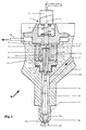
- Fig. 3 shows an alternate embodiment of the injector 4 according to the present invention. Comparing this embodiment with the one shown in Fig. 2, one can see that the spring 48 and the spring support 50 have been eliminated in the embodiment of Fig. 3. Instead a bore or chamber 54 extends from the underside 63a of the thinner section 63 of the needle valve piston 60 to the tip 55 and to the region 54a immediately around and upstream the needle valve seat 56. This results in a more compact design of the lower portion of the injector 4.
- the force resulting from the pressurized fuel within the injector 4 provides a closing bias to keep the needle valve 52 seated on its seat 56 inbetween injection events.
- the needle valve 52 can be opened by the cylinder compression pressure while restarting the engine 2 when the fuel pressure in the injection system is low. This can result in a temporary blow-back of air and of solid particles from the engine's cylinder across the injection orifices 58 and the valve seat 56 into the bore 54. In turn the solid particles can contaminate the contact area of the needle valve 52 and injector tip 55 at the common seat 56 with adverse effects to the seal tightness of the seat 56 when the injection system is pressurized.
- the injector 4 it is possible to eliminate the spring 48 while still maintaining a closing bias for the injector needle valve 52 with no fuel pressure in the injection system.
- the two fits of the thinner section 63 in the guide-piece 62 and of the thicker section 69 in the piece 71 are tight slide-fits, typically with a clearance of 1 to 3 microns, since the needle valve 52 must be axially shiftable to allow for the momentary injection event.
- the solenoid valve spring 88 (Fig. 3)
- the valve stem 76 will push the piece 71 to contact the top end 69a of the thicker section 69 of the needle valve piston 60.
- the spring 88 (Fig. 3) has two functions, namely a dynamic one when the injector 4 is operating during running conditions of the engine 2 and the solenoid 74 raises the valve stem 76 to allow for the momentary injection events, and static, safety like function, when the engine 2 is not running and the fuel pressure is substantially zero.
- the embodiment shown in Fig. 3 is of a more simple design compared to the embodiment shown in Fig. 2. Additionally the lower portion of the injector 4 can more easily be tailored to the space available within the cylinder head of the related internal combustion engine 2.
- the guide 162 for the thinner section 63 of the needle valve piston 60 is machined directly into the injector housing 44.
- the lower side of the thinner section 63 is press-fitted to the needle valve 52 by means of a press-fit 80.
- the bore 65, machined on the axis of the needle valve piston 60, connects with a side bore 82 in the lower part of the thinner section 63.
- the side bore 82 connects to the bore or chamber 54 of the injector 4.
- This design allows a more simple machining process of the needle valve pistons 60 with respect to the bore 65 in the needle valve piston 60 compared to the solution shown in Fig. 2 or 3.
- an increasing number of electronically controlled fuel injection systems detect the motion of the injector needle valve member by means of a sensor.
- the signals are transmitted by the sensor to an electronic control unit, which can supervise and, if needed, adjust the operating parameters of the fuel injection system to a given optimum.
- the injector 4 of the present invention will suitably be operated by means of an electronic control unit 20, the needle valve lift measurement during actual engine operation is a desirable feature.
- this is a very difficult task to accomplish, since the entire injector needle valve member including the entire needle valve piston are under high fuel pressure during operation of the system.
- the injector 4 allows to measure the actual movement of the injector needle valve 52 by placing a sensor in a low pressure region of the injector 4, as shown in Fig. 4.
- Such a sensor 84 is placed in the injector body or housing 44 and protrudes into the lower part of the low pressure region 78.
- a counterpiece 86 to the sensor 84 is attached to the thinner section 63 of the needle valve piston 60 at a region above the upper end of the guide 162 for this thinner section 63.
- the counterpiece 86 is firmly connected to the needle valve piston 60, for example by means of a press-fit or by another type of firm connection.
- the needle valve piston 60 and the counterpiece 86 could also be made out of a single piece.
- the injector needle valve 52, the needle valve piston 60 and the counterpiece 86 will perform the same axial movement during the momentary injection event. This movement is detected by the sensor 84.
- the top and lower parts of the injector 4 not shown in Fig. 4 are constructed substantially in the same manner as described earlier in connection with Fig. 2 and 3.
- a fuel injectior of the type as shown in Fig. 3 is also shown and described in EP-A-0 264 640.
Landscapes
- Engineering & Computer Science (AREA)
- Chemical & Material Sciences (AREA)
- Combustion & Propulsion (AREA)
- Mechanical Engineering (AREA)
- General Engineering & Computer Science (AREA)
- Physics & Mathematics (AREA)
- Fluid Mechanics (AREA)
- Fuel-Injection Apparatus (AREA)
- Electrical Control Of Air Or Fuel Supplied To Internal-Combustion Engine (AREA)
Claims (9)
Priority Applications (1)
| Application Number | Priority Date | Filing Date | Title |
|---|---|---|---|
| AT87113752T ATE59885T1 (de) | 1986-09-25 | 1987-09-19 | Kraftstoffeinspritzventil. |
Applications Claiming Priority (2)
| Application Number | Priority Date | Filing Date | Title |
|---|---|---|---|
| CH383686 | 1986-09-25 | ||
| CH3836/86 | 1986-09-25 |
Publications (2)
| Publication Number | Publication Date |
|---|---|
| EP0262539A1 EP0262539A1 (fr) | 1988-04-06 |
| EP0262539B1 true EP0262539B1 (fr) | 1991-01-09 |
Family
ID=4264513
Family Applications (2)
| Application Number | Title | Priority Date | Filing Date |
|---|---|---|---|
| EP87113751A Expired - Lifetime EP0264640B1 (fr) | 1986-09-25 | 1987-09-19 | Système d'injection de combustible à réglage électronique |
| EP87113752A Expired - Lifetime EP0262539B1 (fr) | 1986-09-25 | 1987-09-19 | Soupape d'injection de combustible |
Family Applications Before (1)
| Application Number | Title | Priority Date | Filing Date |
|---|---|---|---|
| EP87113751A Expired - Lifetime EP0264640B1 (fr) | 1986-09-25 | 1987-09-19 | Système d'injection de combustible à réglage électronique |
Country Status (5)
| Country | Link |
|---|---|
| US (2) | US4798186A (fr) |
| EP (2) | EP0264640B1 (fr) |
| JP (2) | JPH07107380B2 (fr) |
| AT (2) | ATE59885T1 (fr) |
| DE (2) | DE3767260D1 (fr) |
Families Citing this family (93)
| Publication number | Priority date | Publication date | Assignee | Title |
|---|---|---|---|---|
| DE3855969T2 (de) * | 1987-12-02 | 1998-03-05 | Ganser Hydromag | Elektromagnetisch betätigbare Vorrichtung zum schnellen Umschalten eines elektro-hydraulisch betätigten Kraftstoffeinspritzventils |
| US4899935A (en) * | 1988-03-14 | 1990-02-13 | Yamaha Hatsudoki Kabushiki Kaisha | Valve support for accumulator type fuel injection nozzle |
| JPH01244144A (ja) * | 1988-03-25 | 1989-09-28 | Yamaha Motor Co Ltd | エンジンの高圧燃料噴射装置 |
| GB2223799A (en) * | 1988-10-11 | 1990-04-18 | Lucas Ind Plc | I.C. engine fuel injection nozzle |
| JP2753712B2 (ja) * | 1988-10-17 | 1998-05-20 | ヤマハ発動機株式会社 | エンジンの高圧燃料噴射装置 |
| DE3843162A1 (de) * | 1988-12-22 | 1990-06-28 | Bosch Gmbh Robert | Kraftstoffeinspritzpumpe fuer brennkraftmaschinen |
| DE3936619A1 (de) * | 1989-11-03 | 1991-05-08 | Man Nutzfahrzeuge Ag | Verfahren zum einspritzen eines brennstoffes in einen brennraum einer luftverdichtenden, selbstzuendenden brennkraftmaschine, sowie vorrichtungen zur durchfuehrung dieses verfahrens |
| GB2240587A (en) * | 1990-02-03 | 1991-08-07 | Lucas Ind Plc | I.c. engine fuel injection nozzle |
| FR2673246B1 (fr) * | 1991-02-25 | 1994-01-28 | Melchior Jean | Dispositif d'injection de liquide, notamment de combustible, dans au moins une chambre pressurisee d'une machine a fonctionnement periodique tel que moteur a combustion interne et moteur de ce type equipe de ce dispositif. |
| US5738071A (en) * | 1991-05-22 | 1998-04-14 | Wolff Controls Corporation | Apparatus and method for sensing movement of fuel injector valve |
| BR9107316A (pt) * | 1991-10-11 | 1994-04-19 | Caterpillar Inc | Conjunto de atuador e valvula para um injetor controlado eletronicamente |
| US5235954A (en) * | 1992-07-09 | 1993-08-17 | Anatoly Sverdlin | Integrated automated fuel system for internal combustion engines |
| US5355856A (en) * | 1992-07-23 | 1994-10-18 | Paul Marius A | High pressure differential fuel injector |
| EP0824190B1 (fr) * | 1992-12-23 | 2002-03-06 | Ganser-Hydromag Ag | Soupape d'injection de combustible |
| US5438968A (en) * | 1993-10-06 | 1995-08-08 | Bkm, Inc. | Two-cycle utility internal combustion engine |
| DE4341543A1 (de) * | 1993-12-07 | 1995-06-08 | Bosch Gmbh Robert | Kraftstoffeinspritzeinrichtung für Brennkraftmaschinen |
| US6161770A (en) | 1994-06-06 | 2000-12-19 | Sturman; Oded E. | Hydraulically driven springless fuel injector |
| US6257499B1 (en) | 1994-06-06 | 2001-07-10 | Oded E. Sturman | High speed fuel injector |
| DE4427378C2 (de) * | 1994-08-03 | 1996-07-11 | Bosch Gmbh Robert | Magnetventilgesteuerte Einspritzdüse zur Kraftstoffeinspritzung in den Brennraum einer Dieselbrennkraftmaschine |
| AT1624U1 (de) * | 1995-03-30 | 1997-08-25 | Avl Verbrennungskraft Messtech | Speichereinspritzsystem mit voreinspritzung für eine brennkraftmaschine |
| DE19616812B4 (de) * | 1995-04-27 | 2004-09-30 | Nippon Soken, Inc., Nishio | Kraftstoffeinspritzvorrichtung |
| GB9508623D0 (en) * | 1995-04-28 | 1995-06-14 | Lucas Ind Plc | "Fuel injection nozzle" |
| US6148778A (en) | 1995-05-17 | 2000-11-21 | Sturman Industries, Inc. | Air-fuel module adapted for an internal combustion engine |
| EP0745764B1 (fr) * | 1995-06-02 | 2001-03-21 | Ganser-Hydromag Ag | Soupape d'injection de combustible pour moteurs à combustion interne |
| DE19532599A1 (de) * | 1995-09-04 | 1997-03-06 | Siemens Ag | Common-Rail-Kraftstoffversorgungssystem |
| US6027037A (en) * | 1995-12-05 | 2000-02-22 | Denso Corporation | Accumulator fuel injection apparatus for internal combustion engine |
| US5819704A (en) * | 1996-07-25 | 1998-10-13 | Cummins Engine Company, Inc. | Needle controlled fuel system with cyclic pressure generation |
| US5685273A (en) * | 1996-08-07 | 1997-11-11 | Bkm, Inc. | Method and apparatus for controlling fuel injection in an internal combustion engine |
| DE19632196B4 (de) * | 1996-08-09 | 2004-11-04 | Robert Bosch Gmbh | Elektromagnetisch betätigbares Ventil |
| JP3653882B2 (ja) * | 1996-08-31 | 2005-06-02 | いすゞ自動車株式会社 | エンジンの燃料噴射装置 |
| US5681146A (en) | 1996-10-04 | 1997-10-28 | Future Sea Farms Inc. | Low head pumping system for fish farms |
| DE69719461T2 (de) | 1996-11-21 | 2004-01-15 | Denso Corp | Speicherkraftstoffeinspritzvorrichtung für Verbrennungsmotor |
| DE19712135C1 (de) * | 1997-03-22 | 1998-08-13 | Mtu Friedrichshafen Gmbh | Kraftstoffeinspritzsystem für eine Brennkraftmaschine |
| US5860597A (en) * | 1997-03-24 | 1999-01-19 | Cummins Engine Company, Inc. | Injection rate shaping nozzle assembly for a fuel injector |
| GB9714647D0 (en) * | 1997-07-12 | 1997-09-17 | Lucas Ind Plc | Injector |
| DE19732802A1 (de) * | 1997-07-30 | 1999-02-04 | Bosch Gmbh Robert | Kraftstoffeinspritzvorrichtung für Brennkraftmaschinen |
| US6142125A (en) * | 1997-08-22 | 2000-11-07 | Isuzu Motors Limited | Supply pump for common rail fuel injection system |
| US6199533B1 (en) | 1999-02-01 | 2001-03-13 | Cummins Engine Company, Inc. | Pilot valve controlled three-way fuel injection control valve assembly |
| DE19746568C2 (de) * | 1997-10-22 | 2000-11-02 | Daimler Chrysler Ag | Kraftstoffeinspritzanlage für eine mehrzylindrige Brennkraftmaschine |
| IT1296143B1 (it) * | 1997-11-18 | 1999-06-09 | Elasis Sistema Ricerca Fiat | Dispositivo di comando di un iniettore di combustibile per motori a combustione interna. |
| US5988142A (en) * | 1997-12-22 | 1999-11-23 | Stanadyne Automotive Corp. | Duration control of common rail fuel injector |
| US5890653A (en) * | 1998-04-23 | 1999-04-06 | Stanadyne Automotive Corp. | Sensing and control methods and apparatus for common rail injectors |
| US5875764A (en) * | 1998-05-13 | 1999-03-02 | Siemens Aktiengesellschaft | Apparatus and method for valve control |
| US6085991A (en) | 1998-05-14 | 2000-07-11 | Sturman; Oded E. | Intensified fuel injector having a lateral drain passage |
| DE19907544C2 (de) * | 1999-02-22 | 2002-12-05 | Siemens Ag | Injektor für eine Einspritzanlage einer Brennkraftmaschine |
| DE19933328A1 (de) * | 1999-07-16 | 2001-01-25 | Bosch Gmbh Robert | Common-Rail-Injektor |
| DE19936667A1 (de) * | 1999-08-04 | 2001-02-22 | Bosch Gmbh Robert | Common-Rail-Injektor |
| DE19939419A1 (de) * | 1999-08-20 | 2001-03-01 | Bosch Gmbh Robert | Kraftstoffeinspritzeinrichtung |
| DE19939939A1 (de) * | 1999-08-23 | 2001-04-19 | Bosch Gmbh Robert | Injektor für ein Common-Rail-Einspritzsystem für Brennkraftmaschinen mit kompakter Bauweise |
| DE60014813T2 (de) * | 1999-08-31 | 2006-03-09 | Denso Corp., Kariya | Kraftstoffeinspritzvorrichtung |
| DE19950223A1 (de) * | 1999-10-19 | 2001-04-26 | Bosch Gmbh Robert | Injektor für ein Common-Rail-Einspritzsystem für Brennkraftmaschinen mit teilweisem Kraftausgleich der Düsennadel |
| DE19958565B4 (de) * | 1999-12-04 | 2009-04-16 | Dr. Ing. H.C. F. Porsche Aktiengesellschaft | Kraftstoffversorgungseinrichtung für eine mehrzylindrige Brennkraftmaschine |
| US6293254B1 (en) * | 2000-01-07 | 2001-09-25 | Cummins Engine Company, Inc. | Fuel injector with floating sleeve control chamber |
| US6499467B1 (en) | 2000-03-31 | 2002-12-31 | Cummins Inc. | Closed nozzle fuel injector with improved controllabilty |
| DE10055267B4 (de) * | 2000-11-08 | 2004-07-29 | Robert Bosch Gmbh | Druckgesteuerter Injektor für Hocheinspritzung mit Schieberdrosseln |
| JP3555588B2 (ja) * | 2001-03-23 | 2004-08-18 | トヨタ自動車株式会社 | コモンレール式燃料噴射装置 |
| DE10121340A1 (de) * | 2001-05-02 | 2002-11-14 | Bosch Gmbh Robert | Common-Rail-Injektor |
| DE10122245A1 (de) * | 2001-05-08 | 2002-12-12 | Bosch Gmbh Robert | Leckagereduzierter druckgesteuerter Kraftstoffinjektor |
| DE10122256A1 (de) * | 2001-05-08 | 2002-11-21 | Bosch Gmbh Robert | Kraftstoff-Einspritzvorrichtung für Brennkraftmaschinen, insbesondere Common-Rail-Injektor, sowie Kraftstoffsystem und Brennkraftmaschine |
| DE10155406A1 (de) * | 2001-11-10 | 2003-05-22 | Bosch Gmbh Robert | Kraftstoffeinspritzeinrichtung für eine Brennkraftmaschine |
| US7331329B2 (en) * | 2002-07-15 | 2008-02-19 | Caterpillar Inc. | Fuel injector with directly controlled highly efficient nozzle assembly and fuel system using same |
| JP2005069135A (ja) * | 2003-08-26 | 2005-03-17 | Toyota Motor Corp | 燃料噴射装置 |
| DE10350892A1 (de) * | 2003-10-31 | 2005-06-09 | Siemens Ag | Einspritzsystem für eine Brennkraftmaschine, insbesondere für einen Dieselmotor |
| EP1718862B1 (fr) * | 2004-02-25 | 2010-11-03 | Ganser-Hydromag AG | Soupape d'injection de carburant pour moteurs a combustion interne |
| EP1621764B1 (fr) * | 2004-06-30 | 2007-11-07 | C.R.F. Società Consortile per Azioni | Injecteur d'un moteur à combustion interne |
| DE602004004254T2 (de) * | 2004-06-30 | 2007-07-12 | C.R.F. S.C.P.A. | Servoventil zum Steuern eines Einspritzventils einer Brennkraftmaschine |
| US7334741B2 (en) * | 2005-01-28 | 2008-02-26 | Cummins Inc. | Fuel injector with injection rate control |
| DE102005026514B4 (de) * | 2005-02-18 | 2008-12-24 | Robert Bosch Gmbh | Einspritzdüse |
| DE102005014180A1 (de) * | 2005-03-29 | 2006-10-05 | Robert Bosch Gmbh | Kraftstoffeinspritzeinrichtung für eine Brennkraftmaschine |
| DE102005022534B4 (de) * | 2005-05-17 | 2012-12-20 | Continental Automotive Gmbh | Einspritzventil |
| EP1731752B1 (fr) | 2005-05-27 | 2010-01-20 | C.R.F. Società Consortile per Azioni | Soupape asservie de contrôle de carburant et injecteur de carburant avec une telle soupape |
| JP5120655B2 (ja) | 2005-07-18 | 2013-01-16 | ガンサー−ハイドロマグ アーゲー | 内燃機関用の蓄圧式噴射システム |
| US7415969B2 (en) * | 2006-02-28 | 2008-08-26 | Caterpillar Inc. | Fuel injector having recessed check top |
| CN101078388B (zh) * | 2006-05-25 | 2012-09-26 | C.R.F.索奇埃塔·孔索尔蒂莱·佩尔·阿齐奥尼 | 燃油控制伺服阀以及设有该伺服阀的燃油喷射器 |
| US7353806B2 (en) * | 2006-09-06 | 2008-04-08 | Cummins Inc. | Fuel injector with pressure balancing valve |
| DE102007002282A1 (de) * | 2007-01-16 | 2008-07-17 | Robert Bosch Gmbh | Kraftstoffinjektor mit Koppler |
| US7658179B2 (en) * | 2008-05-28 | 2010-02-09 | Caterpillar Inc. | Fluid leak limiter |
| DE102008036300B3 (de) * | 2008-08-04 | 2010-01-28 | Mtu Friedrichshafen Gmbh | Verfahren zur Steuerung einer Brennkraftmaschine in V-Anordnung |
| US7661410B1 (en) | 2008-08-18 | 2010-02-16 | Caterpillar Inc. | Fluid leak limiter |
| US9163597B2 (en) * | 2008-10-01 | 2015-10-20 | Caterpillar Inc. | High-pressure containment sleeve for nozzle assembly and fuel injector using same |
| US7832374B2 (en) * | 2008-10-21 | 2010-11-16 | Gm Global Technology Operations, Inc. | Fuel pressure amplifier |
| DE102009002793B4 (de) * | 2009-05-04 | 2011-07-07 | MTU Friedrichshafen GmbH, 88045 | Common-Rail-Kraftstoffeinspritzsystem sowie Brennkraftmaschine, Elektronische Einrichtung und Verfahren zur Steuerung und/oder Regelung einer Brennkraftmaschine |
| US8201543B2 (en) * | 2009-05-14 | 2012-06-19 | Cummins Intellectual Properties, Inc. | Piezoelectric direct acting fuel injector with hydraulic link |
| US8479711B2 (en) * | 2009-06-10 | 2013-07-09 | Cummins Intellectual Propeties, Inc. | Piezoelectric direct acting fuel injector with hydraulic link |
| JP5303418B2 (ja) * | 2009-09-29 | 2013-10-02 | 本田技研工業株式会社 | 燃料供給装置 |
| US8584655B2 (en) | 2009-09-29 | 2013-11-19 | Honda Motor Co., Ltd. | Fuel heating device |
| CH705729A1 (de) * | 2011-11-07 | 2013-05-15 | Liebherr Machines Bulle Sa | Einspritzsystem. |
| US9651013B2 (en) * | 2012-04-24 | 2017-05-16 | International Engine Intellectual Property Company, Llc | Low leakage seat valve guide |
| US8775054B2 (en) | 2012-05-04 | 2014-07-08 | GM Global Technology Operations LLC | Cold start engine control systems and methods |
| JP6182905B2 (ja) * | 2013-03-01 | 2017-08-23 | 株式会社デンソー | 燃料レール |
| EP2829718B1 (fr) * | 2013-07-22 | 2016-07-13 | Delphi International Operations Luxembourg S.à r.l. | Agencement d'injecteur |
| US9822748B2 (en) * | 2014-05-31 | 2017-11-21 | Cummins Inc. | Restrictive flow passage in common rail injectors |
| IT201900025390A1 (it) * | 2019-12-23 | 2021-06-23 | Westport Fuel Systems Italia S R L | Gruppo regolatore di pressione per un impianto di alimentazione di un carburante gassoso ad un motore a combustione interna |
Citations (1)
| Publication number | Priority date | Publication date | Assignee | Title |
|---|---|---|---|---|
| US4258674A (en) * | 1979-03-28 | 1981-03-31 | Wolff George D | Engine fuel injection system |
Family Cites Families (21)
| Publication number | Priority date | Publication date | Assignee | Title |
|---|---|---|---|---|
| BE554051A (fr) * | 1956-01-31 | |||
| CH434875A (de) * | 1966-06-21 | 1967-04-30 | Huber Robert | Brennstoff-Einspritzventil mit elektromagnetischer Betätigung |
| CH495504A (de) * | 1968-08-28 | 1970-08-31 | Sopromi Soc Proc Modern Inject | Brennstoff-Einspritzventil mit elektromagnetischer Betätigung |
| US3908621A (en) * | 1973-04-25 | 1975-09-30 | Ambac Ind | Hydraulically loaded injector nozzle |
| DD122574A1 (fr) * | 1975-10-24 | 1976-10-12 | Karl Marx Stadt Automobilbau | |
| GB2045347B (en) * | 1979-02-24 | 1983-04-20 | Huber Motorenbau Inst | I c engine fuel injection system |
| JPS57135260A (en) * | 1981-02-17 | 1982-08-20 | Nissan Motor Co Ltd | Fuel injecting device of diesel engine |
| DE3105686A1 (de) * | 1981-02-17 | 1982-09-02 | Robert Bosch Gmbh, 7000 Stuttgart | "kraftstoffeinspritzduese" |
| JPS5820959A (ja) * | 1981-07-30 | 1983-02-07 | Diesel Kiki Co Ltd | 燃料噴射装置の燃料増圧器に圧油の供給を制御する弁装置 |
| AT378242B (de) * | 1981-07-31 | 1985-07-10 | Berchtold Max Prof | Kraftstoffeinspritzanlage fuer brennkraftmaschinen, insbesondere dieselmotoren |
| DE3148671A1 (de) * | 1981-12-09 | 1983-07-21 | Robert Bosch Gmbh, 7000 Stuttgart | Kraftstoffeinspritzvorrichtung fuer brennkraftmaschinen, insbesondere fuer dieselmotoren |
| JPS58155274A (ja) * | 1982-03-12 | 1983-09-14 | Mitsubishi Heavy Ind Ltd | 燃料噴射装置 |
| JPS5930215U (ja) * | 1982-08-17 | 1984-02-24 | 株式会社ヨシダ | 歯肉嚢測定用器具 |
| FR2541379B1 (fr) * | 1983-02-21 | 1987-06-12 | Renault | Perfectionnement aux systemes d'injection a commande electromagnetique pour moteur diesel de type pression-temps ou l'aiguille de l'injecteur est pilotee par la decharge puis la charge d'une capacite |
| JPS6043165A (ja) * | 1983-08-17 | 1985-03-07 | Nippon Soken Inc | 内燃機関用燃料噴射弁 |
| US4603671A (en) * | 1983-08-17 | 1986-08-05 | Nippon Soken, Inc. | Fuel injector for an internal combustion engine |
| JPS60204961A (ja) * | 1984-03-29 | 1985-10-16 | Mazda Motor Corp | デイ−ゼルエンジンの燃料噴射装置 |
| US4709679A (en) * | 1985-03-25 | 1987-12-01 | Stanadyne, Inc. | Modular accumulator injector |
| US4674448A (en) * | 1985-07-04 | 1987-06-23 | Sulzer Brothers Limited | Fuel injection system for a multi-cylinder reciprocating internal combustion engine |
| ES2042184T3 (es) * | 1985-12-02 | 1993-12-01 | Marco Alfredo Ganser | Dispositivo para el control de los inyectores de combustible de accionamiento electrohidraulico. |
| CH668621A5 (de) * | 1986-01-22 | 1989-01-13 | Dereco Dieselmotoren Forschung | Kraftstoffeinspritzanlage fuer eine brennkraftmaschine. |
-
1987
- 1987-09-19 DE DE8787113752T patent/DE3767260D1/de not_active Expired - Fee Related
- 1987-09-19 DE DE87113751T patent/DE3788406T2/de not_active Expired - Fee Related
- 1987-09-19 EP EP87113751A patent/EP0264640B1/fr not_active Expired - Lifetime
- 1987-09-19 AT AT87113752T patent/ATE59885T1/de not_active IP Right Cessation
- 1987-09-19 AT AT87113751T patent/ATE98340T1/de not_active IP Right Cessation
- 1987-09-19 EP EP87113752A patent/EP0262539B1/fr not_active Expired - Lifetime
- 1987-09-25 JP JP62239080A patent/JPH07107380B2/ja not_active Expired - Fee Related
- 1987-09-25 US US07/100,949 patent/US4798186A/en not_active Expired - Lifetime
- 1987-09-25 JP JP62239079A patent/JP2539635B2/ja not_active Expired - Fee Related
- 1987-09-25 US US07/101,101 patent/US4838231A/en not_active Expired - Lifetime
Patent Citations (1)
| Publication number | Priority date | Publication date | Assignee | Title |
|---|---|---|---|---|
| US4258674A (en) * | 1979-03-28 | 1981-03-31 | Wolff George D | Engine fuel injection system |
Also Published As
| Publication number | Publication date |
|---|---|
| JPS63147966A (ja) | 1988-06-20 |
| DE3767260D1 (de) | 1991-02-14 |
| US4798186A (en) | 1989-01-17 |
| EP0262539A1 (fr) | 1988-04-06 |
| ATE59885T1 (de) | 1991-01-15 |
| DE3788406D1 (de) | 1994-01-20 |
| JP2539635B2 (ja) | 1996-10-02 |
| EP0264640B1 (fr) | 1993-12-08 |
| US4838231A (en) | 1989-06-13 |
| EP0264640A1 (fr) | 1988-04-27 |
| JPH07107380B2 (ja) | 1995-11-15 |
| DE3788406T2 (de) | 1994-04-14 |
| ATE98340T1 (de) | 1993-12-15 |
| JPS63147967A (ja) | 1988-06-20 |
Similar Documents
| Publication | Publication Date | Title |
|---|---|---|
| EP0262539B1 (fr) | Soupape d'injection de combustible | |
| US5511528A (en) | Accumulator type of fuel injection device | |
| US5042445A (en) | Electronic controlled fuel supply system for high pressure injector | |
| US5423484A (en) | Injection rate shaping control ported barrel for a fuel injection system | |
| US5740782A (en) | Positive-displacement-metering, electro-hydraulic fuel injection system | |
| JP3521811B2 (ja) | 内燃機関の安全装置 | |
| US4480619A (en) | Flow control device | |
| US6145492A (en) | Control valve for a fuel injection valve | |
| US4972996A (en) | Dual lift electromagnetic fuel injector | |
| US4491111A (en) | Fuel injection apparatus for internal combustion engines | |
| US5487508A (en) | Injection rate shaping control ported check stop for a fuel injection nozzle | |
| US4971016A (en) | Electronic controlled fuel supply system for high pressure injector | |
| US20060042599A1 (en) | Adjustable pressure regulating valve for fuel injection systems | |
| US5127583A (en) | Accumulator type injection nozzle | |
| US5011082A (en) | Perfected diesel engine electromagnetic fuel injector | |
| US5373828A (en) | Fuel injection system | |
| US6988680B1 (en) | Injector of compact design for a common rail injection system for internal combustion engines | |
| US5150684A (en) | High pressure fuel injection unit for engine | |
| US5832954A (en) | Check valve assembly for inhibiting Helmholtz resonance | |
| US4840310A (en) | Fuel injection nozzle | |
| US6820827B1 (en) | Injector for a fuel injection system for internal combustion engines, having a nozzle needle protruding into the valve control chamber | |
| KR0172131B1 (ko) | 전자기 작동식 연료 분사 밸브 | |
| US4674461A (en) | Unit injector for internal combustion engines | |
| US5655502A (en) | Injection timing control device for fuel injection pump | |
| US4745903A (en) | Pressure regulating valve |
Legal Events
| Date | Code | Title | Description |
|---|---|---|---|
| PUAI | Public reference made under article 153(3) epc to a published international application that has entered the european phase |
Free format text: ORIGINAL CODE: 0009012 |
|
| AK | Designated contracting states |
Kind code of ref document: A1 Designated state(s): AT CH DE ES FR GB IT LI NL SE |
|
| 17P | Request for examination filed |
Effective date: 19881001 |
|
| 17Q | First examination report despatched |
Effective date: 19890321 |
|
| GRAA | (expected) grant |
Free format text: ORIGINAL CODE: 0009210 |
|
| AK | Designated contracting states |
Kind code of ref document: B1 Designated state(s): AT CH DE ES FR GB IT LI NL SE |
|
| PG25 | Lapsed in a contracting state [announced via postgrant information from national office to epo] |
Ref country code: SE Effective date: 19910109 Ref country code: NL Effective date: 19910109 |
|
| REF | Corresponds to: |
Ref document number: 59885 Country of ref document: AT Date of ref document: 19910115 Kind code of ref document: T |
|
| REF | Corresponds to: |
Ref document number: 3767260 Country of ref document: DE Date of ref document: 19910214 |
|
| ET | Fr: translation filed | ||
| ITF | It: translation for a ep patent filed | ||
| PG25 | Lapsed in a contracting state [announced via postgrant information from national office to epo] |
Ref country code: ES Free format text: LAPSE BECAUSE OF FAILURE TO SUBMIT A TRANSLATION OF THE DESCRIPTION OR TO PAY THE FEE WITHIN THE PRESCRIBED TIME-LIMIT Effective date: 19910420 |
|
| NLV1 | Nl: lapsed or annulled due to failure to fulfill the requirements of art. 29p and 29m of the patents act | ||
| PLBE | No opposition filed within time limit |
Free format text: ORIGINAL CODE: 0009261 |
|
| STAA | Information on the status of an ep patent application or granted ep patent |
Free format text: STATUS: NO OPPOSITION FILED WITHIN TIME LIMIT |
|
| 26N | No opposition filed | ||
| PGFP | Annual fee paid to national office [announced via postgrant information from national office to epo] |
Ref country code: AT Payment date: 19990824 Year of fee payment: 13 |
|
| PG25 | Lapsed in a contracting state [announced via postgrant information from national office to epo] |
Ref country code: AT Free format text: LAPSE BECAUSE OF NON-PAYMENT OF DUE FEES Effective date: 20000919 |
|
| PGFP | Annual fee paid to national office [announced via postgrant information from national office to epo] |
Ref country code: CH Payment date: 20010816 Year of fee payment: 15 |
|
| PGFP | Annual fee paid to national office [announced via postgrant information from national office to epo] |
Ref country code: FR Payment date: 20010904 Year of fee payment: 15 |
|
| REG | Reference to a national code |
Ref country code: GB Ref legal event code: IF02 |
|
| PGFP | Annual fee paid to national office [announced via postgrant information from national office to epo] |
Ref country code: DE Payment date: 20020907 Year of fee payment: 16 |
|
| PG25 | Lapsed in a contracting state [announced via postgrant information from national office to epo] |
Ref country code: CH Free format text: LAPSE BECAUSE OF NON-PAYMENT OF DUE FEES Effective date: 20020930 Ref country code: LI Free format text: LAPSE BECAUSE OF NON-PAYMENT OF DUE FEES Effective date: 20020930 |
|
| REG | Reference to a national code |
Ref country code: CH Ref legal event code: PL |
|
| PG25 | Lapsed in a contracting state [announced via postgrant information from national office to epo] |
Ref country code: FR Free format text: LAPSE BECAUSE OF NON-PAYMENT OF DUE FEES Effective date: 20030603 |
|
| REG | Reference to a national code |
Ref country code: FR Ref legal event code: ST |
|
| PG25 | Lapsed in a contracting state [announced via postgrant information from national office to epo] |
Ref country code: DE Free format text: LAPSE BECAUSE OF NON-PAYMENT OF DUE FEES Effective date: 20040401 |
|
| PGFP | Annual fee paid to national office [announced via postgrant information from national office to epo] |
Ref country code: GB Payment date: 20050912 Year of fee payment: 19 |
|
| PG25 | Lapsed in a contracting state [announced via postgrant information from national office to epo] |
Ref country code: IT Free format text: LAPSE BECAUSE OF NON-PAYMENT OF DUE FEES;WARNING: LAPSES OF ITALIAN PATENTS WITH EFFECTIVE DATE BEFORE 2007 MAY HAVE OCCURRED AT ANY TIME BEFORE 2007. THE CORRECT EFFECTIVE DATE MAY BE DIFFERENT FROM THE ONE RECORDED. Effective date: 20050919 |
|
| GBPC | Gb: european patent ceased through non-payment of renewal fee |
Effective date: 20060919 |
|
| PG25 | Lapsed in a contracting state [announced via postgrant information from national office to epo] |
Ref country code: GB Free format text: LAPSE BECAUSE OF NON-PAYMENT OF DUE FEES Effective date: 20060919 |