EP0261735B1 - Vorrichtung zum Erfassen der Temperatur in wasserführenden Rohrleitungen - Google Patents
Vorrichtung zum Erfassen der Temperatur in wasserführenden Rohrleitungen Download PDFInfo
- Publication number
- EP0261735B1 EP0261735B1 EP87201799A EP87201799A EP0261735B1 EP 0261735 B1 EP0261735 B1 EP 0261735B1 EP 87201799 A EP87201799 A EP 87201799A EP 87201799 A EP87201799 A EP 87201799A EP 0261735 B1 EP0261735 B1 EP 0261735B1
- Authority
- EP
- European Patent Office
- Prior art keywords
- temperature detection
- detection elements
- box
- shaped body
- temperature
- Prior art date
- Legal status (The legal status is an assumption and is not a legal conclusion. Google has not performed a legal analysis and makes no representation as to the accuracy of the status listed.)
- Expired - Lifetime
Links
- XLYOFNOQVPJJNP-UHFFFAOYSA-N water Substances O XLYOFNOQVPJJNP-UHFFFAOYSA-N 0.000 title claims description 5
- 238000001514 detection method Methods 0.000 claims description 11
- 239000004020 conductor Substances 0.000 claims description 3
- 229920003023 plastic Polymers 0.000 claims description 2
- 239000004033 plastic Substances 0.000 claims description 2
- 230000002093 peripheral effect Effects 0.000 claims 1
- 239000007788 liquid Substances 0.000 description 5
- 239000002184 metal Substances 0.000 description 2
- 238000005406 washing Methods 0.000 description 2
- 230000001419 dependent effect Effects 0.000 description 1
- 230000005489 elastic deformation Effects 0.000 description 1
- 239000012858 resilient material Substances 0.000 description 1
- 239000012487 rinsing solution Substances 0.000 description 1
Images
Classifications
-
- A—HUMAN NECESSITIES
- A47—FURNITURE; DOMESTIC ARTICLES OR APPLIANCES; COFFEE MILLS; SPICE MILLS; SUCTION CLEANERS IN GENERAL
- A47L—DOMESTIC WASHING OR CLEANING; SUCTION CLEANERS IN GENERAL
- A47L15/00—Washing or rinsing machines for crockery or tableware
- A47L15/42—Details
- A47L15/4287—Temperature measuring or regulating arrangements
-
- D—TEXTILES; PAPER
- D06—TREATMENT OF TEXTILES OR THE LIKE; LAUNDERING; FLEXIBLE MATERIALS NOT OTHERWISE PROVIDED FOR
- D06F—LAUNDERING, DRYING, IRONING, PRESSING OR FOLDING TEXTILE ARTICLES
- D06F34/00—Details of control systems for washing machines, washer-dryers or laundry dryers
- D06F34/14—Arrangements for detecting or measuring specific parameters
- D06F34/22—Condition of the washing liquid, e.g. turbidity
- D06F34/24—Liquid temperature
-
- G—PHYSICS
- G01—MEASURING; TESTING
- G01K—MEASURING TEMPERATURE; MEASURING QUANTITY OF HEAT; THERMALLY-SENSITIVE ELEMENTS NOT OTHERWISE PROVIDED FOR
- G01K13/00—Thermometers specially adapted for specific purposes
- G01K13/02—Thermometers specially adapted for specific purposes for measuring temperature of moving fluids or granular materials capable of flow
-
- D—TEXTILES; PAPER
- D06—TREATMENT OF TEXTILES OR THE LIKE; LAUNDERING; FLEXIBLE MATERIALS NOT OTHERWISE PROVIDED FOR
- D06F—LAUNDERING, DRYING, IRONING, PRESSING OR FOLDING TEXTILE ARTICLES
- D06F2103/00—Parameters monitored or detected for the control of domestic laundry washing machines, washer-dryers or laundry dryers
- D06F2103/16—Washing liquid temperature
Definitions
- thermostats that are inserted directly into the washing or rinsing solution.
- thermostats with switching elements or thermal sensors are often brought into direct contact with a part of the water-bearing pipes.
- Such sensors are usually attached via screw or clamp connections, regardless of whether the sensor itself is designed as a switching element or only works as a temperature-sensitive element with downstream electronics and switching elements.
- thermostats to the outer wall of liquid containers made of metal.
- fasteners have to be attached to the container walls, which are difficult to install, especially in the case of large wall parts, without disturbing the smooth inner surfaces and where the thermostats only work effectively if there is always liquid at the jetty, which is hardly possible with devices with a small water consumption is fulfilled.
- thermostats described in FR-A-2 441 157 which are tied into the container walls via rubber seals, have the same or similar disadvantages, apart from the problems associated with the seals used.
- the invention is based on the object of specifying a device with which elements for temperature detection can be brought into thermal contact with the liquid carried in pipelines in a simple manner. According to the invention, this is done in a device for detecting the temperature in water-carrying pipelines using temperature detection elements in that a connection piece is formed on the side of the pipe, into which a can-shaped body made of heat-conducting material for receiving the temperature detection elements is inserted in a liquid-tight manner, and in that a molded part in the manner of a clamping bracket is placed on the can-shaped body and presses the elements used against the bottom surface of the can-shaped body under elastic deformation.
- a device of this type it is possible to mount any temperature-sensing elements individually or as a group without intervention in the liquid circuit and also to replace them in the event of service.
- a device according to the invention also makes it possible to use different elements for temperature detection in a wide variety of devices with the same design or to use elements of different types in the same device. The only requirement for this is that the elements themselves are of the same design from the body.
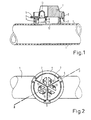
- Fig. 1 shows in section partly in section
- Fig. 2 in plan a device according to the invention in use on a pipeline.
- a cylindrical connecting piece 2 is attached laterally, preferably integrally, which has a can-shaped body 3 made of highly conductive Material, such as metal, liquid-tight, for example by vulcanizing, absorbs.
- the can-shaped body 3 has an outwardly angled plate edge 4.
- a molded part 5 made of resilient material, for example plastic, is placed on the can-shaped body 3 and held at the edge 4 with bow-shaped latching parts 6.
- the molded part 5 has ribs 7 which stiffen it and shield the electrical connections 13 from one another. Parts 8 projecting downwards form holders for the temperature detection elements 9.
- the molded part 5 is shaped in parts so that it forms spring clips 10 which press the temperature sensing elements 9 against the bottom 12 of the body 3 with their feet 11.
- the temperature detection elements 9 can be designed as switching thermostats or as sensor elements with a temperature-dependent internal resistance. The connection is made via the electrical contacts 13.
- thermocouples or thermostats can be easily inserted or exchanged.
Landscapes
- Engineering & Computer Science (AREA)
- Textile Engineering (AREA)
- Physics & Mathematics (AREA)
- General Physics & Mathematics (AREA)
- Measuring Temperature Or Quantity Of Heat (AREA)
Description
- Bei elektrischen Geschirrspülmaschinen und ähnlichen Geräten ist es notwendig, das Gerät auch abhängig von der Temperatur der Wasch- oder Spülflüssigkeit zu steuern. In der Regel geschieht dies unter Verwendung von Thermostaten, die direkt in die Wasch- oder Spüllauge eingesetzt sind. Bei bestimmten Gerätetypen, insbesondere beim Einsatz von Durchlauferhitzern, werden Thermostate mit Schaltelementen oder auch Thermofühler häufig unmittelbar in Kontakt mit einem Teil der wasserführenden Rohrleitungen gebracht. Die Anbringung derartiger Meßfühler geschieht meist über Schraub- oder Klemmverbindungen unabhängig davon, ob der Fühler selbst als Schaltelement ausgebildet oder nur als temperaturempfindliches Element mit einer nachgeschalteten Elektronik und Schaltelementen arbeitet.
- Ferner ist es bekannt, an die Außenwandung von Flüssigkeitsbehältern aus Metall Thermostate anzulegen. Hierfür sind an den Behälterwandungen Befestigungselemente anzubringen, die insbesondere bei großflächigen Wandungsteilen nur schwer ohne Störung der glatten Innenflächen anzubringen sind und bei denen die Thermostate nur dann wirksam arbeiten, wenn an der Anlegestelle immer Flüssigkeit vorhanden ist, was bei Geräten mit einem kleinen Wasserverbrauch kaum zu erfüllen ist.
- Auch die in der FR-A-2 441 157 beschriebenen Thermostate, die über Gummidichtungen in Behälterwandungen eingeknüpft sind, haben gleiche oder gleichartige Nachteile, von den mit eingesetzten Dichtungen verbundenen Problemen einmal abgesehen.
- Der Erfingdung liegt die Aufgabe zugrunde, eine Vorrichtung anzugeben, mit der man in einfacher Art und Weise Elemente zur Temperaturerfassung in Wärmekontakt mit der in Rohrleitungen geführten Flüssigkeit bringen kann. Gemäß der Erfindung geschieht dies bei einer Vorrichtung zum Erfassen der Temperatur in wasserführenden Rohrleitungen unter Verwendung von Temperaturerfassungselementen dadurch, daß an die Rohrleitung seitlich ein Stutzen angeformt ist, in den flüssigkeitsdicht ein dosenförmiger Körper aus wärmeleitendem Material zur Aufnahme der Temperaturerfassungs-elemente eingesetzt ist und daß auf den dosenförmigen Körper ein Formteil nach Art eines Klemmbügels aufgesetzt ist, der unter elastischer Deformation die eingesetzten Elemente gegen die Bodenfläche des dosenförmigen Körpers preßt.
- Mit einer Vorrichtung dieser Art ist es möglich, beliebige, die Temperatur erfassenden Elemente einzeln oder auch als Gruppe ohne Eingriff in den Flüssigkeitskreislauf zu montieren und im Servicefall auch auszutauschen. Eine Vorrichtung nach der Erfindung ermöglicht es auch, bei gleicher Aufbauform unterschiedliche Elemente zur Temperaturerfassung in die verschiedensten Geräte einzusetzen oder auch im gleichen Gerät verschiedenartig wirkende Elemente zu verwenden. Voraussetzung dafür ist nur, daß die Elemente selbst vom Körper her gleichartig ausgebildet sind.
- Vorteilhafte Ausführungsformen der Vorrichtung nach der Erfindung werden anhand der Zeichnung beschrieben und die Wirkungsweise erläutert.
- Die Fig. 1 zeigt im Aufriß zum Teil im Schnitt und
- die Fig. 2 im Grundriß eine Vorrichtung nach der Erfindung im Einsatz an einer Rohrleitung.
- An eine Rohrleitung 1, z.B. ein Formschlauch, ist seitlich ein zylindrischer Stutzen 2 angesetzt, vorzugsweise angeformt, der einen dosenförmigen Körper 3 aus gut leitenden Material, z.B. Metall, flüssigkeitsdicht, z.B. durch einvulkanisieren, aufnimmt. Der dosenförmige Körper 3 hat einen nach außen abgewinkelten Tellerrand 4. Ein aus federelastischem Material, z.B. Kunststoff, gefertigtes Formteil 5 ist auf den dosenförmigen Körper 3 aufgesetzt und mit bügelförmigen Rastteilen 6 am Rand 4 gehaltert. Das Formteil 5 hat Rippen 7, die es in sich versteifen und die elektrischen Anschlüsse 13, gegeneinander abschirmen. Nach unten abstehende Teile 8 bilden Halter für die Temperaturerfassungselemente 9.
- Das Formteil 5 ist in Teilen so ausgeformt, daß es Federbügel 10 bildet, die mit ihren Füßen 11 die Temperaturerfassungselemente 9 gegen den Boden 12 des Körpers 3 drücken. Die Temperaturerfassungselemente 9 können als schaltende Thermostate, oder aber als Fühlerelemente mit einem temperaturabhängigen Innenwiderstand ausgebildet sein. Der Anschluß erfolgt über die elektrischen Kontakte 13.
- Das Formteil 5 mit seinen federelastisch ausgeformten Teilen und den Rastteilen 6 sorgt in einfacher, aber betriebssicherer Weise für einen guten Wärmeübergang zum Innenraum des Rohres 1. Im Montage- und im Servicefall können ein oder mehrere Thermoelemente bzw. Thermostate leicht eingesetzt oder ausgetauscht werden.
Claims (4)
Applications Claiming Priority (2)
| Application Number | Priority Date | Filing Date | Title |
|---|---|---|---|
| DE8625181U DE8625181U1 (de) | 1986-09-20 | 1986-09-20 | Vorrichtung zum Erfassen der Temperatur in wasserführenden Rohrleitungen |
| DE8625181U | 1986-09-20 |
Publications (3)
| Publication Number | Publication Date |
|---|---|
| EP0261735A2 EP0261735A2 (de) | 1988-03-30 |
| EP0261735A3 EP0261735A3 (en) | 1989-08-02 |
| EP0261735B1 true EP0261735B1 (de) | 1991-06-05 |
Family
ID=6798470
Family Applications (1)
| Application Number | Title | Priority Date | Filing Date |
|---|---|---|---|
| EP87201799A Expired - Lifetime EP0261735B1 (de) | 1986-09-20 | 1987-09-15 | Vorrichtung zum Erfassen der Temperatur in wasserführenden Rohrleitungen |
Country Status (2)
| Country | Link |
|---|---|
| EP (1) | EP0261735B1 (de) |
| DE (2) | DE8625181U1 (de) |
Families Citing this family (9)
| Publication number | Priority date | Publication date | Assignee | Title |
|---|---|---|---|---|
| JPS63253223A (ja) * | 1987-04-09 | 1988-10-20 | Terumo Corp | 温度測定器 |
| DE4030415A1 (de) * | 1990-09-26 | 1992-04-02 | Miele & Cie | Rueckstellbarer sicherheitsschalter |
| FR2718236B1 (fr) * | 1994-03-29 | 1996-06-21 | Peugeot | Agencement d'une sonde de température sur une paroi. |
| FR2724727A1 (fr) * | 1994-09-16 | 1996-03-22 | Cotherm Sa | Capteur de temperature |
| EP0710824A1 (de) * | 1994-11-05 | 1996-05-08 | Elth S.A. | Thermischer Sensor |
| DE19755360B4 (de) * | 1997-12-12 | 2006-01-12 | BSH Bosch und Siemens Hausgeräte GmbH | Verfahren zur Temperaturmessung in einem wasserführenden Haushaltsgerät und wasserführendes Haushaltsgerät |
| DE19905741C5 (de) * | 1999-02-11 | 2012-08-09 | BSH Bosch und Siemens Hausgeräte GmbH | Elektrischer Heißwasserbereiter mit einem Thermistor |
| US9360377B2 (en) * | 2013-12-26 | 2016-06-07 | Rosemount Inc. | Non-intrusive temperature measurement assembly |
| RU184470U1 (ru) * | 2018-04-28 | 2018-10-29 | Публичное акционерное общество "Транснефть" (ПАО "Транснефть") | Устройство для установки накладного преобразователя температуры |
Family Cites Families (4)
| Publication number | Priority date | Publication date | Assignee | Title |
|---|---|---|---|---|
| DE7832863U1 (de) * | 1978-11-06 | 1980-01-17 | Bosch-Siemens Hausgeraete Gmbh, 7000 Stuttgart | Temperaturfuehler |
| CH648661A5 (en) * | 1980-09-09 | 1985-03-29 | Elesta Ag Elektronik Bad Ragaz | Contact sensor for measuring the temperature of an object |
| DE3316995A1 (de) * | 1983-05-10 | 1984-11-15 | Bayerische Motoren Werke AG, 8000 München | Temperaturerfassungsvorrichtung |
| DE3327389A1 (de) * | 1983-07-29 | 1985-02-07 | Siemens AG, 1000 Berlin und 8000 München | Temperaturmesssonde |
-
1986
- 1986-09-20 DE DE8625181U patent/DE8625181U1/de not_active Expired
-
1987
- 1987-09-15 DE DE8787201799T patent/DE3770557D1/de not_active Expired - Fee Related
- 1987-09-15 EP EP87201799A patent/EP0261735B1/de not_active Expired - Lifetime
Also Published As
| Publication number | Publication date |
|---|---|
| DE8625181U1 (de) | 1986-11-13 |
| EP0261735A2 (de) | 1988-03-30 |
| EP0261735A3 (en) | 1989-08-02 |
| DE3770557D1 (de) | 1991-07-11 |
Similar Documents
| Publication | Publication Date | Title |
|---|---|---|
| EP0261735A2 (de) | Vorrichtung zum Erfassen der Temperatur in wasserführenden Rohrleitungen | |
| EP2339307B1 (de) | Temperaturmessvorrichtung | |
| WO2014037257A2 (de) | Temperaturmessvorrichtung zur bestimmung der temperatur an der oberfläche einer rohrleitung | |
| EP0702782B1 (de) | Nuggi-thermometer | |
| US20120103089A1 (en) | Encapsulated liquid level sensor device | |
| GB1244870A (en) | Improvements in or relating to electric immersion heaters | |
| CN113384156A (zh) | 一种发热盘温控组件及加热装置及方法 | |
| DE4343919A1 (de) | Thermoskanne | |
| DE59407009D1 (de) | Elektrisch schweissbares Formteil aus Kunststoff | |
| US3565466A (en) | Means to connect a conduit to a container | |
| DE102017218554A1 (de) | Temperaturüberwachungsvorrichtung und Haushaltsgerät mit der Temperaturüberwachungsvorrichtung | |
| DE4237038A1 (de) | Temperaturmeßeinrichtung mit umspritztem Heißleiter | |
| DE7832695U1 (de) | Temperaturfuehler | |
| DE3721983C2 (de) | ||
| DE1438178A1 (de) | Einrichtung zur Steuerung eines Zeitprogramms fuer selbsttaetig arbeitende Haushaltsmaschinen | |
| US2884131A (en) | Liquid level signaling means | |
| FR2428953A3 (fr) | Dispositif etanche destine au montage, au support et au maintien en place de resistances electriques gainees devant etre utilisees dans des machines a laver ou des appareils analogues | |
| US20020157179A1 (en) | Multi-use cleaning device | |
| DE202018106976U1 (de) | Feldgerät mit Temperatur-Distanz-Bestimmungseinheit | |
| DE4237039A1 (de) | Temperaturmeßeinrichtung mit aufgesetzter Kappe | |
| DE102019123761B4 (de) | Niederhalter zum Niederhalten eines Messsensors und Weiterleiten eines elektrischen Messsignals | |
| DE102014008822A1 (de) | Sensor | |
| DE202013006963U1 (de) | Überwachte Vorrichtung zur pegelstands- und temperaturabhängigen Heizungsansteuerung einer metallischen Wanne mitttels Widerstandssensoren und PT100 Temperaturfühler zur Rückstauvermeidung bei niedrigen Temperaturbedingen | |
| DE1969322U (de) | Vorrichtung zur ueberwachung der temperatur einer fluessigkeit mittels eines temperaturabhaengigen widerstandes. | |
| KR200311805Y1 (ko) | 정수기의 냉·온수 파이프 결합용 플랜지 |
Legal Events
| Date | Code | Title | Description |
|---|---|---|---|
| PUAI | Public reference made under article 153(3) epc to a published international application that has entered the european phase |
Free format text: ORIGINAL CODE: 0009012 |
|
| AK | Designated contracting states |
Kind code of ref document: A2 Designated state(s): DE FR GB IT SE |
|
| RAP1 | Party data changed (applicant data changed or rights of an application transferred) |
Owner name: N.V. PHILIPS' GLOEILAMPENFABRIEKEN Owner name: BAUKNECHT HAUSGERAETE GMBH |
|
| RAP1 | Party data changed (applicant data changed or rights of an application transferred) |
Owner name: WHIRLPOOL INTERNATIONAL B.V. Owner name: BAUKNECHT HAUSGERAETE GMBH |
|
| PUAL | Search report despatched |
Free format text: ORIGINAL CODE: 0009013 |
|
| AK | Designated contracting states |
Kind code of ref document: A3 Designated state(s): DE FR GB IT SE |
|
| 17P | Request for examination filed |
Effective date: 19900130 |
|
| 17Q | First examination report despatched |
Effective date: 19900612 |
|
| GRAA | (expected) grant |
Free format text: ORIGINAL CODE: 0009210 |
|
| AK | Designated contracting states |
Kind code of ref document: B1 Designated state(s): DE FR GB IT SE |
|
| REF | Corresponds to: |
Ref document number: 3770557 Country of ref document: DE Date of ref document: 19910711 |
|
| ITF | It: translation for a ep patent filed | ||
| ET | Fr: translation filed | ||
| GBT | Gb: translation of ep patent filed (gb section 77(6)(a)/1977) | ||
| PLBE | No opposition filed within time limit |
Free format text: ORIGINAL CODE: 0009261 |
|
| STAA | Information on the status of an ep patent application or granted ep patent |
Free format text: STATUS: NO OPPOSITION FILED WITHIN TIME LIMIT |
|
| 26N | No opposition filed | ||
| EAL | Se: european patent in force in sweden |
Ref document number: 87201799.1 |
|
| PGFP | Annual fee paid to national office [announced via postgrant information from national office to epo] |
Ref country code: SE Payment date: 19980904 Year of fee payment: 12 |
|
| PGFP | Annual fee paid to national office [announced via postgrant information from national office to epo] |
Ref country code: GB Payment date: 19980908 Year of fee payment: 12 |
|
| PGFP | Annual fee paid to national office [announced via postgrant information from national office to epo] |
Ref country code: FR Payment date: 19980909 Year of fee payment: 12 |
|
| PGFP | Annual fee paid to national office [announced via postgrant information from national office to epo] |
Ref country code: DE Payment date: 19980921 Year of fee payment: 12 |
|
| PG25 | Lapsed in a contracting state [announced via postgrant information from national office to epo] |
Ref country code: GB Free format text: LAPSE BECAUSE OF NON-PAYMENT OF DUE FEES Effective date: 19990915 |
|
| PG25 | Lapsed in a contracting state [announced via postgrant information from national office to epo] |
Ref country code: SE Free format text: THE PATENT HAS BEEN ANNULLED BY A DECISION OF A NATIONAL AUTHORITY Effective date: 19990929 |
|
| GBPC | Gb: european patent ceased through non-payment of renewal fee |
Effective date: 19990915 |
|
| EUG | Se: european patent has lapsed |
Ref document number: 87201799.1 |
|
| PG25 | Lapsed in a contracting state [announced via postgrant information from national office to epo] |
Ref country code: FR Free format text: LAPSE BECAUSE OF NON-PAYMENT OF DUE FEES Effective date: 20000531 |
|
| PG25 | Lapsed in a contracting state [announced via postgrant information from national office to epo] |
Ref country code: DE Free format text: LAPSE BECAUSE OF NON-PAYMENT OF DUE FEES Effective date: 20000701 |
|
| REG | Reference to a national code |
Ref country code: FR Ref legal event code: ST |
|
| PG25 | Lapsed in a contracting state [announced via postgrant information from national office to epo] |
Ref country code: IT Free format text: LAPSE BECAUSE OF NON-PAYMENT OF DUE FEES;WARNING: LAPSES OF ITALIAN PATENTS WITH EFFECTIVE DATE BEFORE 2007 MAY HAVE OCCURRED AT ANY TIME BEFORE 2007. THE CORRECT EFFECTIVE DATE MAY BE DIFFERENT FROM THE ONE RECORDED. Effective date: 20050915 |