EP0260947A2 - Aufschnittschneidmaschine mit Scheibenhäufvorrichtung - Google Patents
Aufschnittschneidmaschine mit Scheibenhäufvorrichtung Download PDFInfo
- Publication number
- EP0260947A2 EP0260947A2 EP87308189A EP87308189A EP0260947A2 EP 0260947 A2 EP0260947 A2 EP 0260947A2 EP 87308189 A EP87308189 A EP 87308189A EP 87308189 A EP87308189 A EP 87308189A EP 0260947 A2 EP0260947 A2 EP 0260947A2
- Authority
- EP
- European Patent Office
- Prior art keywords
- stack
- receiver
- cam
- stack receiver
- slices
- Prior art date
- Legal status (The legal status is an assumption and is not a legal conclusion. Google has not performed a legal analysis and makes no representation as to the accuracy of the status listed.)
- Withdrawn
Links
Images

Classifications
-
- B—PERFORMING OPERATIONS; TRANSPORTING
- B26—HAND CUTTING TOOLS; CUTTING; SEVERING
- B26D—CUTTING; DETAILS COMMON TO MACHINES FOR PERFORATING, PUNCHING, CUTTING-OUT, STAMPING-OUT OR SEVERING
- B26D7/00—Details of apparatus for cutting, cutting-out, stamping-out, punching, perforating, or severing by means other than cutting
- B26D7/27—Means for performing other operations combined with cutting
- B26D7/32—Means for performing other operations combined with cutting for conveying or stacking cut product
-
- Y—GENERAL TAGGING OF NEW TECHNOLOGICAL DEVELOPMENTS; GENERAL TAGGING OF CROSS-SECTIONAL TECHNOLOGIES SPANNING OVER SEVERAL SECTIONS OF THE IPC; TECHNICAL SUBJECTS COVERED BY FORMER USPC CROSS-REFERENCE ART COLLECTIONS [XRACs] AND DIGESTS
- Y10—TECHNICAL SUBJECTS COVERED BY FORMER USPC
- Y10T—TECHNICAL SUBJECTS COVERED BY FORMER US CLASSIFICATION
- Y10T83/00—Cutting
- Y10T83/202—With product handling means
- Y10T83/2033—Including means to form or hold pile of product pieces
- Y10T83/2037—In stacked or packed relation
- Y10T83/2046—Including means to move stack bodily
- Y10T83/2048—By movement of stack holder
- Y10T83/205—By timed relocation of holder along path of stack gscheme-change-itemth
-
- Y—GENERAL TAGGING OF NEW TECHNOLOGICAL DEVELOPMENTS; GENERAL TAGGING OF CROSS-SECTIONAL TECHNOLOGIES SPANNING OVER SEVERAL SECTIONS OF THE IPC; TECHNICAL SUBJECTS COVERED BY FORMER USPC CROSS-REFERENCE ART COLLECTIONS [XRACs] AND DIGESTS
- Y10—TECHNICAL SUBJECTS COVERED BY FORMER USPC
- Y10T—TECHNICAL SUBJECTS COVERED BY FORMER US CLASSIFICATION
- Y10T83/00—Cutting
- Y10T83/202—With product handling means
- Y10T83/2092—Means to move, guide, or permit free fall or flight of product
- Y10T83/2198—Tiltable or withdrawable support
Definitions
- the present invention relates to an apparatus for stacking sliced products from a slicing machine, and more particularly to an apparatus which receives accurately slices of ham, bacon and so on from a slicing machine, stacks a predetermined number of slices and transfers them to conveyor means of a packaging device.
- the paired receiving plates are rotated such that the slices stacked thereon are released to be dropped onto the conveyor, the slices being conveyed in the stacked condition to a packaging machine.
- the receiving plates after releasing the stack onto the conveyor, move up to the initial position at high speed to accumulate a next stack.
- the plates Since, however, the slicing machine continues slicing the loaf while the receiving plates rotate to drop the stack and move up, the plates must be elevated to the initial position immediately with very high speed in order to receive the slices without fail and in order to prevent the slices from free falling a long distance for the purpose of aligning the stack.
- Such a high speed movement of the receiving plates is not advantageous because it entails excessive load on the mechanism and tends to cause vibrations with reducing a lifetime of the machine.
- the vertical movements of the receiving plates are effected by a system incorporating two pneumatic cylinders, resulting in a complicated structure of the machine and a troublesome work for accurately controlling the movements.
- the rotational movements of the receiving plates for releasing the stack tend to displace the slices due to centrifugal force so that the stack dropped on the conveyor is misaligned or misplaced.
- a further object of the invention is to provide an apparatus of the kind set forth above which is relatively simple in structure and reliable in operation.
- an apparatus for stacking sliced products from a slicing machine in which a loaf is fed into a cutting blade to be cyclically sliced includes a first stack receiver and a second stack receiver disposed below the cutting blade.
- Each stack receiver comprises a pair of receiving plates and is operable between a closed position where the receiving plates are adjacent each other for accumulating the slices and an open position where the receiving plates are spaced from each other for releasing the slices.
- Means for moving the first and second stack receivers is provided whereby one of these stack receivers is in the raised position adjacent the cutting blade when the other thereof is in the lowered position away from the cutting blade.
- the apparatus also includes means for operating the stack receivers between the closed position and the open position whereby the stack receiver is closed at the raised position and is opened at the lowered position.
- the second stack receiver When the first stack receiver is open in the uppermost position, the second stack receiver is closed in the lowermost position. From these positions, the first stack receiver is lowered while accumulating the slices, and the second stack receiver is raised. During these movements, since the second stack receiver is opened, it can move up smoothly to the uppermost position while permitting the first stack receiver to pass between the receiving plates of the second stack receiver. When the first stack receiver reaches the lowermost position, it opens to discharge the stack. At the same time the second stack receiver reaches the uppermost position and is closed so that it is ready to receive succeeding slices cut by the blade. By repeating these operations, the apparatus can stack the slices in alignment and release the stacks of slices downward without causing misalignment.
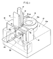
- a box-like body 10 has a support 18 in the form of a gate and secured to a front portion of the upper surface 10a of the body. Disposed on the support 18 are a pair of upright rotary belts 12 which are spaced from each other to feed a loaf 17 therebetween and which include at the lower ends respective drive pulleys connected to a drive device 16 through shafts 15.
- the drive device 16 is attached on the upper surface 10a adjacent the support 18 and connected to a known power transmission mechanism (not shown) within the body 10 for rotating the shafts 15 and therefore the pulleys 14 intermittently.
- the rotary belts 12 advance the loaf 17 a distance which is determined to correspond to a desired thickness of a slice to be cut.
- the upper surface of the support 18 is formed centrally thereof with an opening through which the loaf 17 is permitted to advance downwardly.
- a ring-shaped guide member 19 is fitted in the opening and has an inner diameter substantially equal to the diameter of the loaf 17 to prevent a dispacement of the end portion of the loaf 17 in the horizontal direction.
- a cutting blade 13 Rotatably mounted on the upper surface 10a of the body 10 is a cutting blade 13 which is positioned at a level slightly below the lower end of guide member 19 as seen from FIG. 2.
- a rotational axis 13a of the blade 13 is so eccentric that during rotation the blade 13 cyclically slices the loaf 17.
- the advance of the loaf 17 is effected during the blade 13 is in the inoperated position away from the loaf 17.
- a conveyor 20 is disposed below the guide member 19 to feed the slices as cut to a subsequent process such as packaging.
- An apparatus of the invention is provided to stack a predetermined number of slices as cut by the blade 13 and to transfer the stacked slices to the conveyor 20.
- Tha apparatus 22 includes a first stack receiver 23 and a second stack receiver 24 both disposed between the blade 13 and the conveyor 20.
- each of the stack receivers 23 and 24 comprises a pair of horizontally extending thin plates 25 having a rectangular shape in plane and arranged in side by side relationship.
- the plates 25 of the first stack receiver 23 are fixed at their ends away from the opening of the support 18 to the upper ends of respective vertical shafts 26, so that a rotational movement of the shafts 26 moves the first receiver 23 to an open position where the ends of the plates 25 away from the shafts are spaced from each other or to a closed position where those ends are adjacent each other, depending on a direction of rotation.
- Vertically elongated pinions 27 are fitted on the respective shafts 26 at the lower portion thereof and are engaged with each other.
- the lower ends of these shafts are rotatably secured to a support piece 28 which supports a roller 29 in a rotatable manner.
- the roller 29 rests on a first cylindrical cam 30 having an axis extending in the horizontal direction and rolls along the peripheral surface of the cam 30 as it rotates, whereby the shaft 26 and the first stack receiver 23 fixed thereto are moved up and down.
- the plates 25 of the second stack receiver 24 are fixed to shafts 31 having pinions 32 engaging with each other, the lower ends of shafts 31 being rotatably secured to a support piece 33 supporting a roller 34.
- a second cylindrical cam 35 is provided on which the roller 34 rests to roll along the peripheral surface of the cam as it rotates, thereby moving the second stack receiver 24 up and down.
- Each of the first and second cams 30 and 35 is in the shape of a truncated cone having a trapezoid longitudinal section with a horizontally extending line as shown in FIG. 2.
- These cams 30, 35 are slidably fitted on a common shaft 36 extending in the horizontal direction for co-rotation therewith, in such a manner that the larger-diametered end surfaces 30a and 35a face each other and that there is a 180 degree phase difference between the cams 30 and 35.
- the shaft 36 is keyed to the cams 30, 35 concentrically at the end surfaces 30a, 35a but eccentrically at the smaller-diametered end surfaces 30b, 35b.
- a drive source 37 is attached to one end of the shaft 36 for rotating the same.
- annular grooves 30c, 35c Formed on the peripheral surfaces of the cams 30, 35 adjacent the end surfaces 30a, 35a are annular grooves 30c, 35c, respectively, with which are engaged projections 38 of a cam positioner 39.
- the positioner 39 is adapted to adjust a distance between the two projections 38 by rotating a handle 40, so that the cams 30, 35 can be secured at a desired position along the shaft 36.
- each grooved cam comprises straight portions extending parallel to the end faces of the disk and inclined portions connecting the straight portions.
- a cam follower 45 pivotted at 46 is engaged at its lower end with the grooved cam 43 and is swingably connected at its upper end to the end of a rack 47 which engages with one of the pinions 27.
- a cam follower 48 pivotted at 49 is engaged with the grooved cam 44 and swingably linked to a rack 50 engaging with one of the pinions 32.
- the pinion 27 has a width sufficient to enable the rack 47 to engage therewith through an entire travel of the shaft 26 in the vertical direction. That is, the rack 47 engages with the lower portion of the pinion 27 when the shaft 26 and, therefore, the first stack receiver 23 are in the raised position as shown in FIG. 2. As the shaft 26 descends, the pinion 27 slides relative to the rack 47 while maintaining the engagement therebetween. When the shaft 26 reaches its lowered position, the rack 47 engages with the upper portion of the pinion 27.
- the same arrangements are also applied to the second stack receiver 24 and therefore a further description will be omitted.
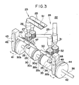
- the apparatus 22 is in the initial position as shown in FIG. 3 in which the first stack receiver 23 is in the raised position with the plates 25 being closed and the second stack receiver 24 is in the lowered position with the plates 25 being open. From this initial position, the first stack receiver 23 gradually descends as the cylindrical cam 30 rotates, while accumulating slices 51 cut by the blade 23. Simultaneously, the second stack receiver 24 is gradually raised, at the same speed as the first stack receiver 24 descends, by the rotation of the cylindrical cam 35. During these vertical movements of the stack receivers the cam followers 45 and 48 are engaged with the straight portions of the grooved cams 43 and 44, respectively. Therefore, the first stack receiver 23 is maintained closed and the second stack receiver 24 is maintained open, permitting the former to pass between the plates 25 of the latter.
- the second stack receiver 24 reaches the uppermost position and the cam follower 48 swings about the pivot 49 in the counterclockwise direction to move the rack 50 toward the left-hand side.
- the second stack receiver 24 is therefore closed for accumulating the slices as cut by the blade 13, the first slice being the one just following the last slice stacked on the first receiver 23.
- the second receiver 24, as in the first receiver 23, gradually descends with maintaining the closed position until a predetermined number of slices are stacked thereon.
- the stack is then released onto the conveyor 20 at the lowermost position of the second receiver 24. At this time, the first receiver 23 has reached its uppermost position as shown in FIG. 3.
- the number of slices in each stack can be varied by changing the rotational speed of either the blade 13 or the shaft 36. For example, if it is desired to reduce the number of slices, either the blade 13 is turned more slowly or the shaft 36 is rotated more rapidly. As the number of slices in each stack decreases, the vertical stroke of the receivers 23, 24 should become shorter. In the above apparatus, the vertical stroke of the receivers 23, 24 is adjustable by the portion of the cylindrical cams 30, 35 on which the rolls 29, 34 rest, and by moving the cylindrical cams along the shaft 36 by the positioner 39 such that a distance between the end surfaces 30a and 35a is changed.
- the above cam mechanism for moving the stack receivers is preferable particularly from the viewpoint of reliability, but various other structures may be used for controlling the movement of the stack receivers.
- the stack receiver may be partly open during descending movement as long as it can receive the slices and may be partly closed during elevation so far as it permits the elevational movement of the other stack receiver.
- the stack receivers may be moved at moderate speed throughout the cycle without a necessity of rapid elevation. This reduces vibration of the apparatus and requires less mechanical strength, facilitating a design and a manufacture. Further, the opening operation of the stack receiver comprising the two plates is carried out by moving the ends of the plates away from each other, and therefore the stack can be maintained as aligned during transfer to the conveyor.
Landscapes
- Life Sciences & Earth Sciences (AREA)
- Forests & Forestry (AREA)
- Engineering & Computer Science (AREA)
- Mechanical Engineering (AREA)
- Stacking Of Articles And Auxiliary Devices (AREA)
- Forming Counted Batches (AREA)
- Pile Receivers (AREA)
Applications Claiming Priority (2)
| Application Number | Priority Date | Filing Date | Title |
|---|---|---|---|
| JP61217251A JPS6374598A (ja) | 1986-09-17 | 1986-09-17 | ハム等のスライス装置用製品受け取り装置 |
| JP217251/86 | 1986-09-17 |
Publications (2)
| Publication Number | Publication Date |
|---|---|
| EP0260947A2 true EP0260947A2 (de) | 1988-03-23 |
| EP0260947A3 EP0260947A3 (de) | 1989-05-03 |
Family
ID=16701219
Family Applications (1)
| Application Number | Title | Priority Date | Filing Date |
|---|---|---|---|
| EP19870308189 Withdrawn EP0260947A3 (de) | 1986-09-17 | 1987-09-16 | Aufschnittschneidmaschine mit Scheibenhäufvorrichtung |
Country Status (4)
| Country | Link |
|---|---|
| US (1) | US4779499A (de) |
| EP (1) | EP0260947A3 (de) |
| JP (1) | JPS6374598A (de) |
| DK (1) | DK478387A (de) |
Cited By (1)
| Publication number | Priority date | Publication date | Assignee | Title |
|---|---|---|---|---|
| EP0670204A1 (de) * | 1994-03-02 | 1995-09-06 | BIFORCE Anstalt | Verfahren und Vorrichtung zur Bildung von Stapeln aus einzelnen Scheiben eines Lebensmittelprodukts |
Families Citing this family (3)
| Publication number | Priority date | Publication date | Assignee | Title |
|---|---|---|---|---|
| NL1018541C2 (nl) | 2001-07-13 | 2003-01-14 | Stork P M T B V | Inrichting voor het masseren van producten. |
| US20070006700A1 (en) * | 2005-07-05 | 2007-01-11 | Lunghi Donald G | Food portioning and application system |
| FR2947537A1 (fr) * | 2009-07-03 | 2011-01-07 | Neopost Technologies | Dispositif de chargement automatique a forte capacite |
Family Cites Families (8)
| Publication number | Priority date | Publication date | Assignee | Title |
|---|---|---|---|---|
| DE1205987B (de) * | 1964-07-25 | 1965-12-02 | Lorenz Hupfauf | Vorrichtung zum Bilden von Stapeln aus Zuschnitten |
| US3498600A (en) * | 1967-12-20 | 1970-03-03 | Paper Converting Machine Co | Delivery apparatus for web segments to be stacked |
| US3821913A (en) * | 1972-09-28 | 1974-07-02 | Chemetron Corp | Apparatus for accumulating stacks of sliced material |
| US3842698A (en) * | 1973-09-11 | 1974-10-22 | C Fitch | Slicing machine for slicing a food product or the like |
| US3955689A (en) * | 1974-03-25 | 1976-05-11 | Chemetron Corporation | Apparatus for accumulating stacks of sliced material |
| JPS578098A (en) * | 1980-06-16 | 1982-01-16 | Omori Machinery | Ham slicer |
| US4405186A (en) * | 1981-10-05 | 1983-09-20 | Formax, Inc. | Movable grid stacker for a food slicing machine |
| US4428263A (en) * | 1981-10-08 | 1984-01-31 | Formax, Inc. | Food loaf slicing machine |
-
1986
- 1986-09-17 JP JP61217251A patent/JPS6374598A/ja active Pending
-
1987
- 1987-09-14 DK DK478387A patent/DK478387A/da not_active Application Discontinuation
- 1987-09-16 EP EP19870308189 patent/EP0260947A3/de not_active Withdrawn
- 1987-09-16 US US07/097,450 patent/US4779499A/en not_active Expired - Fee Related
Cited By (1)
| Publication number | Priority date | Publication date | Assignee | Title |
|---|---|---|---|---|
| EP0670204A1 (de) * | 1994-03-02 | 1995-09-06 | BIFORCE Anstalt | Verfahren und Vorrichtung zur Bildung von Stapeln aus einzelnen Scheiben eines Lebensmittelprodukts |
Also Published As
| Publication number | Publication date |
|---|---|
| JPS6374598A (ja) | 1988-04-05 |
| EP0260947A3 (de) | 1989-05-03 |
| DK478387A (da) | 1988-03-18 |
| DK478387D0 (da) | 1987-09-14 |
| US4779499A (en) | 1988-10-25 |
Similar Documents
| Publication | Publication Date | Title |
|---|---|---|
| US7866130B2 (en) | Automated method for placing sliced food stacks in packages | |
| EP1565395B1 (de) | Vorrichtung und verfahren zum stapeln von aus einer schaltsternanordnung abgeführten flächengebilden | |
| US4583435A (en) | Slab-cutting machine | |
| US4767393A (en) | High speed platen-type die cutter | |
| US3948385A (en) | Apparatus for inverting a sheet member | |
| US3653304A (en) | Apparatus for cutting and creasing sheets | |
| EP2269928B1 (de) | Vorrichtung und Verfahren zum Stapeln von Bögen die von einer Schaufelradanordnung abgeführt werden | |
| US4457656A (en) | Stack assembling apparatus and technique | |
| EP1685047B1 (de) | Vorrichtung zur ausgabe von gestapelten objekten, verfahren zur ausgabe gestapelter objekte und eine ausgabevorrichtung umfassendes system | |
| EP0033835A1 (de) | Vorrichtung zum Ausrichten der Bogen eines Stapels | |
| US3570344A (en) | Apparatus and method for trimming books | |
| US3182537A (en) | Paper cutting machine with counter controlled stacking means | |
| JPS63232996A (ja) | 食品スライス機における可動スタツカ− | |
| JPH10503456A (ja) | シート状生産物のスタックの収集点からの移動装置 | |
| US4779499A (en) | Apparatus for stacking sliced products from slicing machine | |
| GB1171360A (en) | A Stacking Device | |
| US4023513A (en) | Method and apparatus for transferring cans | |
| EP1155993B1 (de) | Vorrichtung zur Ausgabe von gedruckten Papierbögen oder dergleichen in aufeinanderfolgenden Stapeln | |
| US3741535A (en) | Sheet stock feeding mechanism | |
| US3933066A (en) | Dual speed stacker paddle assembly | |
| US4076232A (en) | Apparatus for lifting and conveying a signature fed on a wedge-shaped saddle | |
| CN117001073A (zh) | 一种铅块压锭分切式冷切机 | |
| CA1226811A (en) | High speed platen-type die cutter | |
| JPH0578007A (ja) | スタツカ | |
| EP0068462B1 (de) | Vorrichtung zum Stapeln und zum Bündeln |
Legal Events
| Date | Code | Title | Description |
|---|---|---|---|
| PUAI | Public reference made under article 153(3) epc to a published international application that has entered the european phase |
Free format text: ORIGINAL CODE: 0009012 |
|
| AK | Designated contracting states |
Kind code of ref document: A2 Designated state(s): BE CH DE FR GB IT LI NL |
|
| PUAL | Search report despatched |
Free format text: ORIGINAL CODE: 0009013 |
|
| AK | Designated contracting states |
Kind code of ref document: A3 Designated state(s): BE CH DE FR GB IT LI NL |
|
| 17P | Request for examination filed |
Effective date: 19890621 |
|
| 17Q | First examination report despatched |
Effective date: 19900810 |
|
| STAA | Information on the status of an ep patent application or granted ep patent |
Free format text: STATUS: THE APPLICATION IS DEEMED TO BE WITHDRAWN |
|
| 18D | Application deemed to be withdrawn |
Effective date: 19901221 |
|
| RIN1 | Information on inventor provided before grant (corrected) |
Inventor name: YOKOKAWA, TOSHIYUKI |