US3821913A - Apparatus for accumulating stacks of sliced material - Google Patents
Apparatus for accumulating stacks of sliced material Download PDFInfo
- Publication number
- US3821913A US3821913A US00293144A US29314472A US3821913A US 3821913 A US3821913 A US 3821913A US 00293144 A US00293144 A US 00293144A US 29314472 A US29314472 A US 29314472A US 3821913 A US3821913 A US 3821913A
- Authority
- US
- United States
- Prior art keywords
- slices
- stack
- accumulating
- shaft
- carriage
- Prior art date
- Legal status (The legal status is an assumption and is not a legal conclusion. Google has not performed a legal analysis and makes no representation as to the accuracy of the status listed.)
- Expired - Lifetime
Links
Images


Classifications
-
- B—PERFORMING OPERATIONS; TRANSPORTING
- B26—HAND CUTTING TOOLS; CUTTING; SEVERING
- B26D—CUTTING; DETAILS COMMON TO MACHINES FOR PERFORATING, PUNCHING, CUTTING-OUT, STAMPING-OUT OR SEVERING
- B26D7/00—Details of apparatus for cutting, cutting-out, stamping-out, punching, perforating, or severing by means other than cutting
- B26D7/27—Means for performing other operations combined with cutting
- B26D7/32—Means for performing other operations combined with cutting for conveying or stacking cut product
-
- B—PERFORMING OPERATIONS; TRANSPORTING
- B26—HAND CUTTING TOOLS; CUTTING; SEVERING
- B26D—CUTTING; DETAILS COMMON TO MACHINES FOR PERFORATING, PUNCHING, CUTTING-OUT, STAMPING-OUT OR SEVERING
- B26D2210/00—Machines or methods used for cutting special materials
- B26D2210/02—Machines or methods used for cutting special materials for cutting food products, e.g. food slicers
-
- Y—GENERAL TAGGING OF NEW TECHNOLOGICAL DEVELOPMENTS; GENERAL TAGGING OF CROSS-SECTIONAL TECHNOLOGIES SPANNING OVER SEVERAL SECTIONS OF THE IPC; TECHNICAL SUBJECTS COVERED BY FORMER USPC CROSS-REFERENCE ART COLLECTIONS [XRACs] AND DIGESTS
- Y10—TECHNICAL SUBJECTS COVERED BY FORMER USPC
- Y10T—TECHNICAL SUBJECTS COVERED BY FORMER US CLASSIFICATION
- Y10T83/00—Cutting
- Y10T83/141—With means to monitor and control operation [e.g., self-regulating means]
- Y10T83/145—Including means to monitor product
-
- Y—GENERAL TAGGING OF NEW TECHNOLOGICAL DEVELOPMENTS; GENERAL TAGGING OF CROSS-SECTIONAL TECHNOLOGIES SPANNING OVER SEVERAL SECTIONS OF THE IPC; TECHNICAL SUBJECTS COVERED BY FORMER USPC CROSS-REFERENCE ART COLLECTIONS [XRACs] AND DIGESTS
- Y10—TECHNICAL SUBJECTS COVERED BY FORMER USPC
- Y10T—TECHNICAL SUBJECTS COVERED BY FORMER US CLASSIFICATION
- Y10T83/00—Cutting
- Y10T83/182—With means to weigh product
-
- Y—GENERAL TAGGING OF NEW TECHNOLOGICAL DEVELOPMENTS; GENERAL TAGGING OF CROSS-SECTIONAL TECHNOLOGIES SPANNING OVER SEVERAL SECTIONS OF THE IPC; TECHNICAL SUBJECTS COVERED BY FORMER USPC CROSS-REFERENCE ART COLLECTIONS [XRACs] AND DIGESTS
- Y10—TECHNICAL SUBJECTS COVERED BY FORMER USPC
- Y10T—TECHNICAL SUBJECTS COVERED BY FORMER US CLASSIFICATION
- Y10T83/00—Cutting
- Y10T83/202—With product handling means
- Y10T83/2033—Including means to form or hold pile of product pieces
- Y10T83/2037—In stacked or packed relation
- Y10T83/2046—Including means to move stack bodily
- Y10T83/2048—By movement of stack holder
- Y10T83/205—By timed relocation of holder along path of stack gscheme-change-itemth
Definitions
- ABSTRACT Apparatus for accumulating stacks of sliced material successively cut from an elongated mass comprises a platen mounted on a vertically movable carriage and means for moving the carriage downwardly as the slices are accumulating on said platen. After an accumulation of a desired number of slices in a stack, the platen is rapidly moved to release and discharge the stack and the carriage is moved upwardly on a return stroke to a position ready for the next accumulation cycle.
- the present invention is directed towards an apparatus for accumulating stacks of sliced material in a system for producing weight controlled stacks or groups of counted slices cut from an elongated mass or loaf of material such as food products, for example cold cuts, sausage, cheese or the like.
- Food products such as process cheese, luncheon meats, bologna, salami and the like are produced in elongated loaves, often 4 to 6 feet long, having generally uniform cross-sections of various shapes and dimensions. These products are sold at retail outlets to the consuming public in relatively small packages containing a selected number of relatively thin slices cut transversely from the loaf.
- each package containing a stack or other group of counted slices must have a net food product weight exceeding or at least equal to a weight printed or otherwise indicated on the package. It is desirable to produce such packages which closely meet the weights indicated on the packages with a minimum number of underweight rejects. Also it is very important to minimize the amount of excess food product furnished above the weights indicated on the packages. Thus, great savings can be obtained by mass producing the packages within close tolerances on an automatic weight-controlled slicing system capable of operating at high production rates.
- Prior cutters and weighe rs are capable of maintaining production rates of only about of the production rate of the apparatus of the present invention. Accordingly, the present invention provides great economic savings in terms of an increased production rate, a reduction in the occurrence of underweight and overweight packages and a significant savings in labor cost per package.
- Another object of the present invention is to provide an apparatus of the character described, which is capable of operating at high production rates and maintaining low percentage of underweight rejects while at the same time minimizing the amount of excess packaged food product above the minimum package weight required.
- Another object of the present invention is to provide a new and improved apparatus of the character described which is extremely fast and reliable in operation and which is automatic from the time that a loaf of food product is first introduced into the system until after the weight classified stacks or other groups of counted slices leave the system for further handling.
- Another object of the present invention is to provide a new and improved slicer of the character described in combination with a stacker for accumulating slices cut successively from a loaf and for separating the slices into separate groups containing a selected number of slices.
- Another object of the present invention is to provide a new and improved stacker of the character described wherein each successive slice cut from a loaf fails a substantially constant distance onto a receiver movable downwardly at a rate infinitely variable within a range to equal substantially the rate at which the loaf is fed to be sliced.
- Another object of the present invention is to provide a new and improved stacker of the character described having means for rapidly releasing a group of a counted number of accumulated slices without interruption of the succession of slices from the cutter supplied to the stacker.
- Another object of the present invention is to provide a new and improved stacker of the character described which does not require interruption of the feed of the loaf during the time a group of counted slices is released by the stacker.
- Another object of the present invention is to provide a new and improved stacker of the character described operable to rapidly deposit an accumulated stack of slices onto a weighing device.
- Another object of the present invention is to provide new and improved means for dividing an elongated mass of a food product into a plurality of separate groups, each group having a plurality of separate slices, and means for forming the plurality of separate groups, wherein the forming means includes means for receiving the slices to form the separate groups sequentially, and means for discharging each sequentially formed group from the receiving means in response to a control signal.
- a stacker mechanism for use in an automatically controlled system for producing weight controlled stacks of a selected counter number of slices cut from an elongated mass or load of food product.
- the system includes means for feeding the loaves longitudinally in end-toend relation along a downward feed path at a substantilly constant feed rate into the cutting path of a rotary slicing knife.
- the stack is positioned below the cutting path for receiving and accumulating a selected number of slices into groups and then rapidly releasing or depositing the groups to a weighing system scale for measuring the weight thereof without requiring interruption of the normal feed rate of the loaves fed to the knife of the slicer.
- FIG. 3 is an isometric diagram in schematic animated form illustrating the flow path of movement of the food product as it is moved through the various components of the complete apparatus;
- FIG-4 is an enlarged top plan view looking downwardly into the upper receiving end of a feeder for directing the loaves into the slicer of the apparatus in accordance with the present invention
- FIG. 5 is an elevational sectional view of the feeder taken substantially along line 5-5 of FIG. 4;
- FIG. 6 is an elevational sectional view taken substantially along line 6-6 illustrating a drive train arrangement for the belts of the feeder;
- FIG. 7 is an elevational sectional view of the feeder drive train taken substantially along line 7-7 of FIG. 4;
- FIG. 8 is a horizontal sectional view illustrating a stacker of the apparatus in accordance with the features of the present invention.
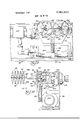
- FIG. 9 is a front elevational view of the stacker
- FIG. 10 is a transverse sectional elevational view taken substantially along line 10-l0 of FIG. 9;
- FIGS. 11a and 11b are aside elevational view of a weighing system and transfer system of the apparatus in accordance with the present invention.
- FIGS. 12a and 12b are a top plan view of the weighing and transfer systems showing a product acceptreject mechanism of the apparatus in accordance with the present invention
- FIG. 12A is a sectional view taken substantially along line l2A-l2A of FIG. 11b, and
- FIGS. 13A, B, and C illustrate schematically an electrical control system for operating and controlling the apparatus of the present invention.
- FIGS. 1, 2 and 3 is illustrated ingeneral fashion a new and improved apparatus constructed in accordance with the features of the present invention for producing weight controlled stacks or groups containing a selected number of slices cut from an elongated mass orloaf of food product such as cheese, meats, cold cuts, sausage, etc.
- the apparatus is especially well adapted for producing discrete or separate groups or stacks of a counted number of slices of food product, each group having a measured weight equalv to or-exceeding a selected net weight which is printed or indicated on the package in which the stack is sold.
- the apparatus includes a loader 30 for receiving elongated masses or loaves 32 of food product or the like and elevating, orienting and feeding the loaves in end-to-end relation onto a downward feed path toward a feeder 34.
- the feeder is adapted to feed the loaves at a selected feed rate into the cutting path of a rotating knife 36 of a slicer.
- the knife is carried on a shaft 38 generally parallel to the feed path of the loaves into the slicer and is driven by a variable speed motor 40 to vary the thickness of the slices to produce stacks or groups meeting a minimum weight requirement for a selected number of slices in a package.
- the knife motor and shaft are supported from a top wall 108 of a knife housing 110, which housing in turn is pivotally supported from a main apparatus housing 164 (FIGS. 1 and 2) on a pair of pivot pin assemblies 168.
- the main housing 164 is supported from a floor or other structure on legs 166.
- the cutting path of the rotating knife 36 beneath the top wall 108 of the knife housing is in shearing relation with the margin or lower edge of a restrictive orifice defining ring 42 positioned at the lower or discharge end of the feeder 34.
- the feeder 34 guides the loaves through the restricted orifice opening I which compresses and holds the product as the slices are cut therefrom.
- the weighing system provides a control sigml for adjusting the speed of the motor 40 and consequently the knife speed to vary the thickness of the slices cut so that subsequent stacks will closely approach a desired optimum weight value.
- the stacks are removed from the scale platform by a transfer system 50 and are classified by a product accept reject mechanism before deposit onto a discharge conveyor 52.
- the weighing system 48 in conjunction with the accept-reject system 51 of the transfer system 50, positions the stacks 46 of slices on the final discharge conveyor 52 in a manner whereby the position of the stacks indicates whether the stack is of acceptable weight or must be rejected because it is underweight or overweight.
- one of the stacks 46 is positioned out of line with respect to the other stacks moving along the conveyor and this out of line position is an indication to an operator at a subsequent processing or machine location that the stack is a reject and should be returned for rework.
- the method and apparatus 20 of the present invention is adapted to handle elongated masses or loaves 32 of meat and other food products such as cheese, etc. which is produced with a variety of different transverse cross sectional shapes and dimensions and the apparatus is adjustable by an operator to produce stacks of slices numbering in a wide range, for example from two to 29 slices per stack, and a wide range of stack lar product being sliced, the number of slices in a stack to provide a given weight may vary somewhat and an operator may select both the number of slices in a stack and a minimum stack weight, as well as a tolerance range for overweight rejects to thereby minimize the amount of extra product supplied over the minimum required.
- a control console 39 with suitable indicators is provided for the operator for monitoring and selecting the number of slices and the weight minimum for the stacks.
- the elongated loaves of product to be sliced are of a substantially uniform cross-section throughout their length exceptpossibly for the ends of the loaves which may be rounded in a sort of bullet shape.
- the loaves 32 are normally brought at random time intervals by trucks or the like to the loader 30 and are unloaded to lay side by side horizontally on a table structure 54 which is positioned at a normal working or supply level.
- the loaves are held in readiness on the table structure and elevated one by one by an upright elevating mechanism 56 to an upper level for eventual discharge in longitudinal end-to-end relation by a lateral discharge conveyor 58.
- the loaves are directed laterally outwardly by the conveyor into a downwardly curving chute structure 60 which changes their direction of feed from generally horizontal toward a vertical feed path into the upper end of the feeder 34. If it is desired or necessary the bullet shaped ends 32a of the loaves may be chopped off or cropped in the loader by a pair of rotating knives 62 driven by motors 64. Details of the loader 30 are set forth in the copending US. Pat. application Ser. No. 293,145 filed Sept. 28, 1972 and assigned to the same assignee as the present applicamen.
- the loaves 32 are directed by the feeder 34 into the slicer 37 along a downward feed path through the restricted orifice opening in the orifice ring 42.
- the feed path intersects the cutting plane of the rotating knife 36 below the top wall 108 of the knife housing.
- the feeder 34 includes a pair of cleated endless belts 66 and 68 driven at a selected speed by a reversible feederretractor motor 70.
- the belts 66 and 68 are cleated on both sides and are driven by a pair of lower drive rolls 72 and 74 having cleat engaging ridges and grooves thereon for positively synchronizing the feed speed of the belts to produce a substantially constant rate of feed into the cutting path.
- the drive roll 72 is mounted on a shaft 76 having a toothed gear 78 on one end, which gear is in driven engagement with a main drive gear 80 (FIG. 6).
- the drive gear 80 is carried on a shaft 82 coupled to the output shaft of the motor 70.
- the cleated belt 66 is movable along a fixed, downwardly extending belt run and the opposite belt 68 is adjustable laterally toward and away from the belt run to accommodate different cross-sectional shapes and sizes of loaves that are handled by the feeder.
- the drive roll 74 of the cleated belt 68 is mounted on a shaft 84 having a gear 86 on one end thereof and this gear is in driving engagement with an idler gear 88 mounted on an idler shaft 90.
- the shaft 90 is linked with the shaft 82 by a pivot link 92 and, as best shown in FIG. 6, as adjustments in the lateral spacing between the endless drive belts 66 and 68 are made, the gear 86 is moved toward and away from the gear 78 (as indicated by the arrow A) while in continuous synchronous driven en-- gagement therewith through the main driven gear 86 and the idler gear 88.
- the shaft 90 includes a flatted end portion 90a which is urged downwardly by a finger 92 biased downwardly by a coil spring 94 (FIG. 7).
- each belt has an inside, downward run opposite and facing the other for positive driving engagement on opposite sides of the loaves 32.
- the belt 66 is provided with a backing guide member 100 having a belt engaging surface formed with alternate ridges and grooves thereon providing an undulated guide path for the driving run of the belt.
- the belt 68 has a similar backing guide member 102 with an undulated guide surface and the ridges on one guide member are disposed opposite the grooves on the opposite guide so that a serpentine path is defined between the guides 100 and 102 by the driving runs of the belts 66 and 68.
- the serpentine path provided by the drive runs of the belts 66 and 68 provides for positive gripping and feeding of the loaves into the slicer 37 and a substantially constant downward feed rate is maintained with very little if any slippage.
- the belt backing guides 100 and 102 insure that each loaf passing through the feeder 34 is positively fed
- the belt 68 and backing structure 102 are supported on a support 104 movable toward and away from the run of the belt 66 which is relatively fixed and supported from a structure 106. Both belt support structures extend upwardly from the top wall 108 of the knife housing 110 are offset from the axis of rotation of the knife.
- the wall 108 is octagonal in shape as shown in FIG.
- the support 106 for the belt 66 includes an upright guide 112 of generally Z-shaped transverse cross-section (HG. 4) and the lower end of this structure is attached to the housing wall 108 by a pair of pivot pins 114 having pull rings in the end for extracting the pins so that the feeder 34 may be disconnected from the knife housing 110 for cleaning or maintenance if required.
- the pins 114 normally extend through aligned apertures in a pair of brackets 116 secured to the guide structure 112 and a pair of upstanding brackets 118 mounted on the top wall 108 of the knife housing.
- the Z-shaped guide 112 is formed with a plurality of spaced apart, horizontal fingers 120 along one flange thereof, said fingers projectving outwardly of the face of the driving run of the belt 66 for engaging and laterally guiding a transverse side of a loaf 32 fed down the feed path into the orifice ring 42.
- the support 104 for the belt 68 includes a similar guide 122 of Z-shaped transverse cross-section (FIG. 4) and this guide has a plurality of spaced apart, horizontal fingers 124 along one flange adapted to extend into the slots and mesh between the fingers 120 of the guide 106 when the spacing interval between the belts 66 and 68 is reduced to accommodate relatively thin loaves of food product.
- Pairs of guide fingers 120 and 124 thus cooperate to provide a transverse guiding surface that is adjustable in width and generally transverse to paths of the driving runs of the endless belts 66 and 68
- the guide structure 122, endless belt 68 and backing member 102 are supported for movement toward and away from the belt 66 from'a pair of parallel horizontal rods 126 disposed outwardly of opposite edges of the belts 66 and 68.
- the support rods extend between sleeves 128 mounted adjacent the upper end of the upright 112 and mounting apertures provided in the upper end of an upright support 130 spaced outwardly of the belt 68.
- the drive shafts 76 and 84 for the drive rolls 72 and 74 and the shafts for the upper idler rolls 96 and 98 of the belts 66 and 68, are mounted and supported on bearings (not shown in detail) carried on the finger flanges of the respective upright guides 112 and 122.
- the guide 122 is provided with a pair of support sleeves 132 similar to the sleeves 128 and in sliding engagement on the support rods 126 so that the belt 68 may be adjusted in the direction of the arrows B in FIGS. 4 and 5 toward and away from the belt 66.
- the upright support 130 is detachably connected to the top wall 108 of the knife housing 110 by means of a pair of removable pins 134 having pull rings at one end and the pins are adapted to project through aligned openings in the lower end of the upright support 130 and a pair of upstanding lugs 136 secured to the knife housing top wall 108 (FIG.
- the entire feeder 34 can be dismounted from the knife housing 110 of the slicer 37 and if only the pins 134 are removed, the structure of the feeder can be pivoted in a counterclockwise direction (FIG. 5) about the axis pins 114 to expose the lower or discharge end of the feeder and expose the removable orifice ring 42.
- Orifice rings having various different shapes and sizes of restricted orifices are insertable in an opening in the housing top wall 108 ofiset outwardly of the axis of the drive shaft 38 of the knife as best shown in FIG. 5. Each time that loaves of a different cross-section are sliced, an appropriately shaped orifice ring is inserted and locked in place in the opening in the knife housing top wall 108.
- Adjustment of the position of the endless belt 68 toward or away from the belt 66 in the directions indicated by the arrows B to accommodate different types of product is set and controlled by a hand wheel 138 mounted on the end of a threaded shaft 140.
- the shaft which extends through an internally threaded collar 142 provided on the upright, 130, is coupled at its inner end to the back side of the guide member 122 via a coupling 144.
- Turning of the hand wheel 138 positively adjusts and holds spacing between the belts 66 and 68 providing a serpentine path of selected width for the loaves 32 fed into the cutting path of the knife 36.
- the feeder 34 is provided with an elongated upright guide bar 146 spaced opposite the cooperating guide fingers 120 and 124 and adjustably positioned to move toward and away from the guide fingers as well as toward and away from the faces of the belts 66 and 68 as indicated in the dotted lines of FIG. 4.
- the guide bar 146 is provided with a pair of support pins 148 extending outwardly and slidably mounted in openings provided in a separate upright member 150.
- the upright 150 in turn is slidably supported on a pair of rods 152 extending outwardly from a relatively fixed member 154.
- a hand wheel 156 on the outer end of a threaded adjustment rod 158 is provided for adjusting (in the direction of the arrows C) and setting the position of the guide bar 146 (FIG. 4) relative to the opposite guide fingers 120 and 124.
- the inner end of the adjustment rod 158 is rotatively coupled to the guide bar and the rod extends through an internally threaded collar attached to the member 150 to provide in and out position adjustment of the guide bar relative to the support member 150.
- the support 150 is slidable on the rods 152 and is movable in the direction of the arrows D.
- Clamping means is provided for securing the mem ber 150 in a selected position on the rods 152 after an adjustment is made and a position is selected.
- the elongated loaves 32 of food product are positively fed at a selected substantially constant rate along the feed path by the driving engagement of driving runs of the cleated feed belts 66 and 68 and the product is compressed and bent in reverse direction as it moves down the serpentine path defined by the belts and their backing members 102.
- Each loaf is positively gripped by the belts and fed into the path of the cutting knife 36 so that little if any slippage occurs.
- the insertable orifice rings 42 are seated in the opening provided in the top wall 108 of the knife housing.
- an appropriate orifice ring 42 is provided for each different cross-sectional shape or size of loaf being slices.
- the rings are dimensioned so that the dimension at the lower edge or margin of the orifice opening is slightly smaller than the normal uncompressed cross-section of the product loaf being sliced.
- the loaves being substantially uniform in cross-section, are compressed inwardly towards the longitudinal axis thereof by engagement with the walls of the orifice ring 42.
- the loaves are also compressed in a longitudinal direction when forced through the orifice ring because the walls of the orifice opening are convergently tapered.
- the orifice ring and its compression effect on the loaf supports the end portion and permits a loaf to be sliced down to its end after it is no longer in engagement with the belts of the feeder.
- the margin or lower edge of the orifice ring 42 is secured in shear cutting relation with the cutting path defined by the cutting edge of the rotating knife 36 so that precise and rapid slicing of the positivelyheld food product loaves 32 is achieved.
- the individual slices fall downwardly from the cutting path for grouping into stacks having a selected number of slices therein by the stacker 44 (FIGS. 8, 9 and 10).
- the slices are cut from the loaves 32 on an uninterrupted basis as the loaves are moved downwardly into the slicer 37 at a constant rate by the feeder 34 through the orifice ring 42.
- the stacker 44 provides for a substantially constant distance of fall for each slice as it leaves the cutting plane to a level whereat the slice is supported either by a preceding slice as the stack is accumulating or by a support platen.
- a substantially constant distance of fall from the cutting path to a support level for each slice being cut is accomplished by providing a vertically reciprocating carriage 160 movable from an upper or starting level on a downward stroke at substantially the same speed as the loaves 32 are fed downwardly by the feeder 34 into the cutting path of the knife 36.
- the stacker 44 of the present invention is operable at very high speeds so that production rates as high as 160 stacks per minute or greater are achieved.
- the stacker includes a rectangular enclosure or housing 162 mounted beneath the knife housing 110 and within the main housing or enclosure 164 of the apparatus.
- the carriage 160 comprises a vertical front plate supporting a pair of horizontal shaft housings 172 which project outwardly thereof and are detachably mounted on the front plate.
- the housings include circular base flanges 174 removably attached to the carriage plate by large headed fasteners 176.
- the shaft housings 172 are aligned in horizontal parallel relation and are spaced on opposite sides of a vertical centerline through the front plate 170 aligned below the downward feed path of loaves moving through the feeder 34 and the slices cut from the loaves by the rotating knife 36. As best shown in FIG.
- the front plate of the stacker carriage is provided with a pair of rearwardly extending lugs 178 having vertical apertures therein and slidably disposed on an upright guide rod 180 for guiding the travel of the carriage in repetitive cycles comprising downward and return strokes.
- the carriage is biased upwardly to an upper starting level by a coil spring 182 disposed on the rod and a cushion 184 is provided adjacent the upper end of the rod to aid in cushioning the carriage at the end of an upward return stroke.
- a pair of incremental stepping motors 186 and 187 are mounted on the back of the carriage plate 170 and the axes of the motors are in coaxial alignment with the left and right hand shaft housings 172.
- the stepping motors are adapted to drive and are detachably coupled to a pair of outwardly extending platen control shafts 188 with each shaft supporting three rows of outwardly extending hair pin shaped fingers 190 arranged in planes spaced at angles 120 apart around the axes of the shafts as viewed in FIG. 9.
- the sets of fingers 190 in each plane on the left hand shaft 188 comprises a paddle-like platen 192 and similarly for the right shaft, platens 192R are formed. Successive pairs of horizontally aligned intermeshing platens 192L and 192R provide support for accumulating successive stacks of sliced product cut from the loaves 32 by the knife 36 in the cutting path above. As best shown in FIG.
- the left and right shafts 188 are indexed by stepping motors in increments of I in opposite directions so that the pairs of platens l92L and 192R cooperate to discharge an accumulated stack downwardly toward the weighing system and the next pair of platens 192L and 192R then form a horizontal support for accumulating the next successive stack of slices 46 thereon.
- the carriage 160 As additional slices are cut and added to a stack formed on the platens, the carriage 160 is traveling downwardly at a rate substantially the same as the rate of feed of the loaves 32 into the cutting path of the knife 36. Accordingly, a substantially constant distance of fall from the cutting path to a support level is provided by the stacker 44 for the successive slices in a stack. As the last slices in the stack are being added the carriage 160 is approaching the lowestmost position, and the stepping motors 186 and 187 are energized by controlled pulses to rotatively index the shafts 188 by 120 in opposite directions as shown in FIG.
- Travel of the carriage 160 on a downward stroke 7 while accumulating the sliced meat product is accomplished by means of a vertical, toothed rack 194 secured to the back of the carriage plate on a supporting structure 196.
- the rack is in meshing engagement with a pinion 198 mounted on a pinion shaft 200 which is coupled to the output shaft of an electromagnetic particle clutch 202.
- An input shaft of the clutch 202 is coupled to a gear reducer 204 which in turn is coupled to the output shaft of a continuously rotating stacker drive motor 206 through a right angle gear box 208 as best shown in FIG. 9.
- the stacker drive motor the speed of which is infinitely variable over a range to enable the rate of downward movement of the carriage 160 substantially to equal the rate at which the load being sliced is fed to the slicer, is continuously energized and running when the apparatus 20 is in operation and the clutch 202 is intermittently supplied with power'for precise intervals of time to rotate the pinion 198 in a counterclockwise direction (arrow P FIG. 10) for driving the carriage on a downward stroke at a selected rate speed.
- the holding current to the clutch 202 is discontinued to release the clutch 202 and the return spring 182 acts to return the carriage upwardly to an initial upper starting level.
- a dashpot assembly 210 is provided on the rear wall of the housing 162.
- the dashpot may be of a rotary type having a forwardly extending shaft 211 with a radial arm 212 secured thereto.
- the dashpot arm is engageable between upper and lower threaded adjustable stops 214 and 215 (FIG. 9), which stops are carried on upper and lower brackets or arms 218 and 219 connected to the carriage plate 170.
- the adjustable stops 214 and 216 engage opposite sides of the arm 212 on the dashpotshaft and oscillate the shaft back and forth, as indicated by the arrow E.
- the dashpot 210 resists oscillatory rotation and thus dampens vibrations of the fast moving carriage 160 as its reverses direction.
- successively accumulated stacks 46 of sliced product cut by the knife 36 are discharged from the pairs of cooperating support platens 192L and 192R upon indexing of the shafts 188 by the stepping motors 186 and 187.
- the discharged stacks 46 fall downwardly onto a scale platform 220 (FIG. 11a) comprising a plurality of spaced apart vertical fingers 222 which are interconnecting at one side and are separated by slots open on the opposite side.
- the platfon'n 220 is mounted on a support rod which extends downwardly and is connected to move a magnetic core of a weight cell 228.
- the weight cell 228 may comprise a transformer adapted to provide an electrical signal which is responsive to the weight of the stack of slices on the scale platform.
- the cell may be arranged to provide a signal representing the difference between the stack of slices being weighed and a selected reference or tare weight.
- the weighing system or mechanism 48 thus provides control signals which are used both for changing the speed of the slicer motor 40 and for activating a product accept-reject mechanism 51 to indicate by placement of the weighed stacks of slices 46 on the discharge conveyor 52 whether the stacks are within an acceptable weight range.
- a repetitive weight measuring cycle is initiated wherein the platform is allowed a period of time to settle so that vibrations from the impact of the falling stack are damped. Following this interval a weight measurement is taken and a signal in response to the measurement is produced. A short interval follows wherein a decision is made to cause the product accept-reject mechanism 51 to accept or reject the stack and to change the rotative speed of the slicer knife 36 if required.
- the weighed stack is removed from the scale platform 220 by the transfer system or mechanism 50 which includes a transfer platen 230 movable horizontally and vertically and comprising a plurality of horizontally spaced apart vertical fingers 232 which are adapted to move in and out and up and down without interference within the open spaces or slots 224 between the fingers 222 on the scale platform.
- the transfer system or mechanism 50 which includes a transfer platen 230 movable horizontally and vertically and comprising a plurality of horizontally spaced apart vertical fingers 232 which are adapted to move in and out and up and down without interference within the open spaces or slots 224 between the fingers 222 on the scale platform.
- the transfer system or mechanism 50 which includes a transfer platen 230 movable horizontally and vertically and comprising a plurality of horizontally spaced apart vertical fingers 232 which are adapted to move in and out and up and down without interference within the open spaces or slots 224 between the fingers 222 on the scale platform.
- the transfer platen 230 moves upwardly to elevate the stack of weighed slices 46 above the scale platform 220 and then moves laterally on a retracting stroke away from the scale (left to right in FIGS. 11a and 11b), to make room for the next stack of slices to be deposited on the scale platform.
- the transfer platen is supported from a reciprocally movable transfer carriage 234 which is activated to move on advancing and retracting strokes by means of a carriage control cylinder 236 controlled by a solenoid actuated valve 238 (FIGS. 13 A, B, C). As indicated diagramatically on FIG.
- the transfer platen 230 moves from a right hand starting or release position along a lower level (arrow F) on an advancing stroke after a new stack of sliced product has been deposited on the scale platform 220 for weighing. After reaching a left hand or pickup position at the lower level and when the weighing cycle is complete, the transfer platen 230 moves upwardly (arrow G) to lift the stack of slices from the scale platform. The platen continues on a retrack stroke (arrow H) from the lifting or pickup position toward the right along an upper level. After the elevated stack of slices clears the right hand edge of the scale platform, the transfer platen 230 is urged downwardly from the upper level on a release or deposit stroke and the stack 46 of slices is deposited onto the upper belt runs of the transfer conveyor 240.
- the transfer conveyor 240 moves the weighed stacks 46 onto an upwardly sloped product accept-reject conveyor 242 of the accept-reject mechanism 51 and ultimately the weighed stacks of slices are deposited onto the discharge conveyor 52 in a position which indicates whether or not the particular stack meets the acceptable minimum weight requirement and is within an acceptable weight range.
- Mechanical means may be provided for removing the rejected stacks for further rework or processing while the acceptable stacks moving 12 along the conveyor 52 are ready for further processing or packaging for market.
- the weighing system 48 includes a large, heavy, base structure 246 (FIG. 1) supported independently of the main housing 164 and other components so that the weight cell 228 will be mounted on a stable solid base isolated from the vibrations of other portions of surrounding mechanism.
- An adjustable base assembly 248 is provided for precisely positioning the scale platform 220 and the associated weight cell 228 in order that the stacks 46 discharged from the stacker platens 192L and 192R will center on the scale.
- a threaded adjustable support post 250 is provided to adjust the vertical level of the upper surface of the scale platform 220 so that only a small amount of upward travel of the transfer platen 230 is required to lift or elevate a stack 46 (arrow G) from the scale platform for lateral transfer to the conveyor 240.
- the weight cell 228 may be provided with a different tare weight and the adjustment post compensates to maintain a constant level of the scale platform relative to the transfer platen.
- the upper stop is interconnected to reciprocating carriage 234 by suitable interconnecting structure indicated by the reference number 251.
- the carriage 234 for supporting the transfer platen 230 is mounted on a pair of horizontal guide rods 256 supported at opposite ends from a main base or frame structure 258 of the transfer mechanism 50.
- the carriage 234 includes a plurality of sleeves slidable on the support rods 256 so that the carriage can move back and forth between the left hand pickup position and the right hand release position.
- a minimum spacing is provided between the stop member 252 and the upper surfaces of the fingers 232 of the transfer platen.
- the stack is held against the stop member by upward pressure from the platen 230 and the stack itself limits the upward movement of the platen during the pickup and retraction strokes.
- the stop 252 is adjustable vertically with respect to the upper level travelled by the transfer platen 230 in order to accommodate stacks 46 of different height or thickness.
- the stop is slidably supported on a rod 249 and reciprocates thereon in a horizontal direction in unison with the carriage 234.
- the stop support rod 249 is mounted on a vertical adjustable frame 253 supported on a pair of threaded posts 255.
- the posts extend upwardly and downwardly from a base plate 257 of the frame 258 in bosses 259 having threaded vertical apertures for theposts.
- Rotation of the posts 255 in unison to maintain a level attitude of the stop 252 during vertical adjustment is achieved by two sprockets 259 on the lower end of the posts and another sprocket on a hand wheel shaft 261.
- the three sprockets are drivingly interconnected by a chain 263 so that rotation of a hand wheel 265 drives the post up or down to adjustthe height of the stop 252 for a particular height of stack being handled.
Landscapes
- Life Sciences & Earth Sciences (AREA)
- Forests & Forestry (AREA)
- Engineering & Computer Science (AREA)
- Mechanical Engineering (AREA)
- Processing Of Meat And Fish (AREA)
Abstract
Apparatus for accumulating stacks of sliced material successively cut from an elongated mass comprises a platen mounted on a vertically movable carriage and means for moving the carriage downwardly as the slices are accumulating on said platen. After an accumulation of a desired number of slices in a stack, the platen is rapidly moved to release and discharge the stack and the carriage is moved upwardly on a return stroke to a position ready for the next accumulation cycle.
Description
United States Patent [191 Bajcar et al.
[ APPARATUS FOR ACCUMULATING STACKS OF SLICED MATERIAL [75] Inventors: Miles S. Bajcar, Palos Hills; Robert Howard Marshall, Hinsdale, both of III.
[73] Assignee: Chemetron Corporation, Chicago,
[22] Filed: Sept. 28, 1972 [2]] Appl. No.: 293,144
[52] HS. Cl 83/92, 83/73, 83/77 [5 1] Int. Cl B2611 5/00 [58] Field of Search 83/92, 73, 77, 14, 19,
[56] References Cited UNITED STATES PATENTS 1.630,099 5/1927 Van Berkel 83/92 [111 3,821,913 July 2,1974
Gillman 83/77 X Lambert et al. 83/73 Primary Examiner-Willie G. Abercrombie [57] ABSTRACT Apparatus for accumulating stacks of sliced material successively cut from an elongated mass comprises a platen mounted on a vertically movable carriage and means for moving the carriage downwardly as the slices are accumulating on said platen. After an accumulation of a desired number of slices in a stack, the platen is rapidly moved to release and discharge the stack and the carriage is moved upwardly on a return stroke to a position ready for the next accumulation cycle.
6 Claims. 18 Drawing Figures PATENTEDJUL 21914 3.821.913-
SHiET 03 0F 13 PATENTEDJUL 2mm 3321.913 SHEET 05 0F 13 PATENTEDJUL 2 m4 saw 07 M13 w ww Nod
PATENTEBJUL 2 \sm SHEET '080F13 I 131821.913 sum 100f13 PATENTEB JUL 2 Fa I j i .R
The present invention is directed towards an apparatus for accumulating stacks of sliced material in a system for producing weight controlled stacks or groups of counted slices cut from an elongated mass or loaf of material such as food products, for example cold cuts, sausage, cheese or the like. Food products such as process cheese, luncheon meats, bologna, salami and the like are produced in elongated loaves, often 4 to 6 feet long, having generally uniform cross-sections of various shapes and dimensions. These products are sold at retail outlets to the consuming public in relatively small packages containing a selected number of relatively thin slices cut transversely from the loaf.
In commercial practice, each package containing a stack or other group of counted slices must have a net food product weight exceeding or at least equal to a weight printed or otherwise indicated on the package. It is desirable to produce such packages which closely meet the weights indicated on the packages with a minimum number of underweight rejects. Also it is very important to minimize the amount of excess food product furnished above the weights indicated on the packages. Thus, great savings can be obtained by mass producing the packages within close tolerances on an automatic weight-controlled slicing system capable of operating at high production rates.
Prior cutters and weighe rs are capable of maintaining production rates of only about of the production rate of the apparatus of the present invention. Accordingly, the present invention provides great economic savings in terms of an increased production rate, a reduction in the occurrence of underweight and overweight packages and a significant savings in labor cost per package.
It is therefore an object of the present invention to provide an apparatus for producing weight controlled stacks of counted slices cut from an elongated mass or loaf of food product.
Another object of the present invention is to provide an apparatus of the character described, which is capable of operating at high production rates and maintaining low percentage of underweight rejects while at the same time minimizing the amount of excess packaged food product above the minimum package weight required.
Another object of the present invention is to provide a new and improved apparatus of the character described which is extremely fast and reliable in operation and which is automatic from the time that a loaf of food product is first introduced into the system until after the weight classified stacks or other groups of counted slices leave the system for further handling.
Another object of the present invention is to provide a new and improved slicer of the character described in combination with a stacker for accumulating slices cut successively from a loaf and for separating the slices into separate groups containing a selected number of slices.
Another object of the present invention is to provide a new and improved stacker of the character described wherein each successive slice cut from a loaf fails a substantially constant distance onto a receiver movable downwardly at a rate infinitely variable within a range to equal substantially the rate at which the loaf is fed to be sliced. 1
Another object of the present invention is to provide a new and improved stacker of the character described having means for rapidly releasing a group of a counted number of accumulated slices without interruption of the succession of slices from the cutter supplied to the stacker.
Another object of the present invention is to provide a new and improved stacker of the character described which does not require interruption of the feed of the loaf during the time a group of counted slices is released by the stacker.
Another object of the present invention is to provide a new and improved stacker of the character described operable to rapidly deposit an accumulated stack of slices onto a weighing device.
Another object of the present invention is to provide new and improved means for dividing an elongated mass of a food product into a plurality of separate groups, each group having a plurality of separate slices, and means for forming the plurality of separate groups, wherein the forming means includes means for receiving the slices to form the separate groups sequentially, and means for discharging each sequentially formed group from the receiving means in response to a control signal.
These and other objects, features, and advantages of the present invention will be evident from the following description, with the aid of the accompanying drawings, of a preferred embodiment of the present invention.
Briefly, in a preferred embodiment of the apparatus of the present invention there is provided a stacker mechanism for use in an automatically controlled system for producing weight controlled stacks of a selected counter number of slices cut from an elongated mass or load of food product. The system includes means for feeding the loaves longitudinally in end-toend relation along a downward feed path at a substantilly constant feed rate into the cutting path of a rotary slicing knife. The stack is positioned below the cutting path for receiving and accumulating a selected number of slices into groups and then rapidly releasing or depositing the groups to a weighing system scale for measuring the weight thereof without requiring interruption of the normal feed rate of the loaves fed to the knife of the slicer.
For a better understanding of the present invention reference should be had to the following detailed de- FIG. 3 is an isometric diagram in schematic animated form illustrating the flow path of movement of the food product as it is moved through the various components of the complete apparatus;
FIG-4 is an enlarged top plan view looking downwardly into the upper receiving end of a feeder for directing the loaves into the slicer of the apparatus in accordance with the present invention;
FIG. 5 is an elevational sectional view of the feeder taken substantially along line 5-5 of FIG. 4;
FIG. 6 is an elevational sectional view taken substantially along line 6-6 illustrating a drive train arrangement for the belts of the feeder;
FIG. 7 is an elevational sectional view of the feeder drive train taken substantially along line 7-7 of FIG. 4;
FIG. 8 is a horizontal sectional view illustrating a stacker of the apparatus in accordance with the features of the present invention;
FIG. 9 is a front elevational view of the stacker;
FIG. 10 is a transverse sectional elevational view taken substantially along line 10-l0 of FIG. 9;
FIGS. 11a and 11b are aside elevational view of a weighing system and transfer system of the apparatus in accordance with the present invention;
FIGS. 12a and 12b are a top plan view of the weighing and transfer systems showing a product acceptreject mechanism of the apparatus in accordance with the present invention;
FIG. 12A is a sectional view taken substantially along line l2A-l2A of FIG. 11b, and
FIGS. 13A, B, and C illustrate schematically an electrical control system for operating and controlling the apparatus of the present invention.
DESCRIPTION OF THE APPARATUS Referring now more particularly to the drawings, in FIGS. 1, 2 and 3 is illustrated ingeneral fashion a new and improved apparatus constructed in accordance with the features of the present invention for producing weight controlled stacks or groups containing a selected number of slices cut from an elongated mass orloaf of food product such as cheese, meats, cold cuts, sausage, etc. The apparatus is especially well adapted for producing discrete or separate groups or stacks of a counted number of slices of food product, each group having a measured weight equalv to or-exceeding a selected net weight which is printed or indicated on the package in which the stack is sold. The apparatus includes a loader 30 for receiving elongated masses or loaves 32 of food product or the like and elevating, orienting and feeding the loaves in end-to-end relation onto a downward feed path toward a feeder 34. The feeder is adapted to feed the loaves at a selected feed rate into the cutting path of a rotating knife 36 of a slicer. The knife is carried on a shaft 38 generally parallel to the feed path of the loaves into the slicer and is driven by a variable speed motor 40 to vary the thickness of the slices to produce stacks or groups meeting a minimum weight requirement for a selected number of slices in a package. The knife motor and shaft are supported from a top wall 108 of a knife housing 110, which housing in turn is pivotally supported from a main apparatus housing 164 (FIGS. 1 and 2) on a pair of pivot pin assemblies 168. The main housing 164 is supported from a floor or other structure on legs 166.
As shown in FIG. 5, the cutting path of the rotating knife 36 beneath the top wall 108 of the knife housing is in shearing relation with the margin or lower edge of a restrictive orifice defining ring 42 positioned at the lower or discharge end of the feeder 34. The feeder 34 guides the loaves through the restricted orifice opening I which compresses and holds the product as the slices are cut therefrom. As the slices are cut by the knife .quirement. The weighing system provides a control sigml for adjusting the speed of the motor 40 and consequently the knife speed to vary the thickness of the slices cut so that subsequent stacks will closely approach a desired optimum weight value. After weighing of the stacks has been completed the stacks are removed from the scale platform by a transfer system 50 and are classified by a product accept reject mechanism before deposit onto a discharge conveyor 52.
In accordance with the present invention the weighing system 48, in conjunction with the accept-reject system 51 of the transfer system 50, positions the stacks 46 of slices on the final discharge conveyor 52 in a manner whereby the position of the stacks indicates whether the stack is of acceptable weight or must be rejected because it is underweight or overweight. As shown in FIG. 2, one of the stacks 46 is positioned out of line with respect to the other stacks moving along the conveyor and this out of line position is an indication to an operator at a subsequent processing or machine location that the stack is a reject and should be returned for rework.
The method and apparatus 20 of the present invention is adapted to handle elongated masses or loaves 32 of meat and other food products such as cheese, etc. which is produced with a variety of different transverse cross sectional shapes and dimensions and the apparatus is adjustable by an operator to produce stacks of slices numbering in a wide range, for example from two to 29 slices per stack, and a wide range of stack lar product being sliced, the number of slices in a stack to provide a given weight may vary somewhat and an operator may select both the number of slices in a stack and a minimum stack weight, as well as a tolerance range for overweight rejects to thereby minimize the amount of extra product supplied over the minimum required. A control console 39 with suitable indicators is provided for the operator for monitoring and selecting the number of slices and the weight minimum for the stacks. The elongated loaves of product to be sliced are of a substantially uniform cross-section throughout their length exceptpossibly for the ends of the loaves which may be rounded in a sort of bullet shape.
The loaves 32 are normally brought at random time intervals by trucks or the like to the loader 30 and are unloaded to lay side by side horizontally on a table structure 54 which is positioned at a normal working or supply level. The loaves are held in readiness on the table structure and elevated one by one by an upright elevating mechanism 56 to an upper level for eventual discharge in longitudinal end-to-end relation by a lateral discharge conveyor 58. The loaves are directed laterally outwardly by the conveyor into a downwardly curving chute structure 60 which changes their direction of feed from generally horizontal toward a vertical feed path into the upper end of the feeder 34. If it is desired or necessary the bullet shaped ends 32a of the loaves may be chopped off or cropped in the loader by a pair of rotating knives 62 driven by motors 64. Details of the loader 30 are set forth in the copending US. Pat. application Ser. No. 293,145 filed Sept. 28, 1972 and assigned to the same assignee as the present applicamen.
The loaves 32 are directed by the feeder 34 into the slicer 37 along a downward feed path through the restricted orifice opening in the orifice ring 42. The feed path intersects the cutting plane of the rotating knife 36 below the top wall 108 of the knife housing. The feeder 34 includes a pair of cleated endless belts 66 and 68 driven at a selected speed by a reversible feederretractor motor 70. The belts 66 and 68 are cleated on both sides and are driven by a pair of lower drive rolls 72 and 74 having cleat engaging ridges and grooves thereon for positively synchronizing the feed speed of the belts to produce a substantially constant rate of feed into the cutting path. The drive roll 72 is mounted on a shaft 76 having a toothed gear 78 on one end, which gear is in driven engagement with a main drive gear 80 (FIG. 6). The drive gear 80 is carried on a shaft 82 coupled to the output shaft of the motor 70. The cleated belt 66 is movable along a fixed, downwardly extending belt run and the opposite belt 68 is adjustable laterally toward and away from the belt run to accommodate different cross-sectional shapes and sizes of loaves that are handled by the feeder. The drive roll 74 of the cleated belt 68 is mounted on a shaft 84 having a gear 86 on one end thereof and this gear is in driving engagement with an idler gear 88 mounted on an idler shaft 90. The shaft 90 is linked with the shaft 82 by a pivot link 92 and, as best shown in FIG. 6, as adjustments in the lateral spacing between the endless drive belts 66 and 68 are made, the gear 86 is moved toward and away from the gear 78 (as indicated by the arrow A) while in continuous synchronous driven en-- gagement therewith through the main driven gear 86 and the idler gear 88. In order to insure that the idler gear 88 is continuously biased into driving engagement between the gears 80 and 86, the shaft 90 includes a flatted end portion 90a which is urged downwardly by a finger 92 biased downwardly by a coil spring 94 (FIG. 7).
The upper ends of the belts are supported by idler rolls 96 and 98 respectively and each belt has an inside, downward run opposite and facing the other for positive driving engagement on opposite sides of the loaves 32. As best shown in FIG. 5 the belt 66 is provided with a backing guide member 100 having a belt engaging surface formed with alternate ridges and grooves thereon providing an undulated guide path for the driving run of the belt. The belt 68 has a similar backing guide member 102 with an undulated guide surface and the ridges on one guide member are disposed opposite the grooves on the opposite guide so that a serpentine path is defined between the guides 100 and 102 by the driving runs of the belts 66 and 68. The serpentine path provided by the drive runs of the belts 66 and 68 provides for positive gripping and feeding of the loaves into the slicer 37 and a substantially constant downward feed rate is maintained with very little if any slippage. The belt backing guides 100 and 102 insure that each loaf passing through the feeder 34 is positively fed In order to accommodate loaves 32 having various different cross sections and transverse dimensions, the belt 68 and backing structure 102 are supported on a support 104 movable toward and away from the run of the belt 66 which is relatively fixed and supported from a structure 106. Both belt support structures extend upwardly from the top wall 108 of the knife housing 110 are offset from the axis of rotation of the knife. The wall 108 is octagonal in shape as shown in FIG. 2 and normally is positioned to overly a similarly shaped opening in the top wall of the main housing 164 when the slicer is in a normal operating position. When it is desired to clean the slicer or change the knife 36, the knife housing 110 is pivoted on the pivot axles 168 to expose the underside of the wall 102 and knife 36. The support 106 for the belt 66 includes an upright guide 112 of generally Z-shaped transverse cross-section (HG. 4) and the lower end of this structure is attached to the housing wall 108 by a pair of pivot pins 114 having pull rings in the end for extracting the pins so that the feeder 34 may be disconnected from the knife housing 110 for cleaning or maintenance if required. The pins 114 normally extend through aligned apertures in a pair of brackets 116 secured to the guide structure 112 and a pair of upstanding brackets 118 mounted on the top wall 108 of the knife housing.
As best shown in FIG. 5, the Z-shaped guide 112 is formed with a plurality of spaced apart, horizontal fingers 120 along one flange thereof, said fingers projectving outwardly of the face of the driving run of the belt 66 for engaging and laterally guiding a transverse side of a loaf 32 fed down the feed path into the orifice ring 42. The support 104 for the belt 68 includes a similar guide 122 of Z-shaped transverse cross-section (FIG. 4) and this guide has a plurality of spaced apart, horizontal fingers 124 along one flange adapted to extend into the slots and mesh between the fingers 120 of the guide 106 when the spacing interval between the belts 66 and 68 is reduced to accommodate relatively thin loaves of food product. Pairs of guide fingers 120 and 124 thus cooperate to provide a transverse guiding surface that is adjustable in width and generally transverse to paths of the driving runs of the endless belts 66 and 68 The guide structure 122, endless belt 68 and backing member 102 are supported for movement toward and away from the belt 66 from'a pair of parallel horizontal rods 126 disposed outwardly of opposite edges of the belts 66 and 68. The support rods extend between sleeves 128 mounted adjacent the upper end of the upright 112 and mounting apertures provided in the upper end of an upright support 130 spaced outwardly of the belt 68. The drive shafts 76 and 84 for the drive rolls 72 and 74 and the shafts for the upper idler rolls 96 and 98 of the belts 66 and 68, are mounted and supported on bearings (not shown in detail) carried on the finger flanges of the respective upright guides 112 and 122. The guide 122 is provided with a pair of support sleeves 132 similar to the sleeves 128 and in sliding engagement on the support rods 126 so that the belt 68 may be adjusted in the direction of the arrows B in FIGS. 4 and 5 toward and away from the belt 66. The upright support 130 is detachably connected to the top wall 108 of the knife housing 110 by means of a pair of removable pins 134 having pull rings at one end and the pins are adapted to project through aligned openings in the lower end of the upright support 130 and a pair of upstanding lugs 136 secured to the knife housing top wall 108 (FIG. By removing both sets of pins 114 and 134, the entire feeder 34 can be dismounted from the knife housing 110 of the slicer 37 and if only the pins 134 are removed, the structure of the feeder can be pivoted in a counterclockwise direction (FIG. 5) about the axis pins 114 to expose the lower or discharge end of the feeder and expose the removable orifice ring 42.
Orifice rings having various different shapes and sizes of restricted orifices are insertable in an opening in the housing top wall 108 ofiset outwardly of the axis of the drive shaft 38 of the knife as best shown in FIG. 5. Each time that loaves of a different cross-section are sliced, an appropriately shaped orifice ring is inserted and locked in place in the opening in the knife housing top wall 108.
Adjustment of the position of the endless belt 68 toward or away from the belt 66 in the directions indicated by the arrows B to accommodate different types of product is set and controlled by a hand wheel 138 mounted on the end of a threaded shaft 140. The shaft, which extends through an internally threaded collar 142 provided on the upright, 130, is coupled at its inner end to the back side of the guide member 122 via a coupling 144. Turning of the hand wheel 138 positively adjusts and holds spacing between the belts 66 and 68 providing a serpentine path of selected width for the loaves 32 fed into the cutting path of the knife 36.
Referring to FIG. 4, the feeder 34 is provided with an elongated upright guide bar 146 spaced opposite the cooperating guide fingers 120 and 124 and adjustably positioned to move toward and away from the guide fingers as well as toward and away from the faces of the belts 66 and 68 as indicated in the dotted lines of FIG. 4. The guide bar 146 is provided with a pair of support pins 148 extending outwardly and slidably mounted in openings provided in a separate upright member 150. The upright 150 in turn is slidably supported on a pair of rods 152 extending outwardly from a relatively fixed member 154. A hand wheel 156 on the outer end of a threaded adjustment rod 158 is provided for adjusting (in the direction of the arrows C) and setting the position of the guide bar 146 (FIG. 4) relative to the opposite guide fingers 120 and 124. The inner end of the adjustment rod 158 is rotatively coupled to the guide bar and the rod extends through an internally threaded collar attached to the member 150 to provide in and out position adjustment of the guide bar relative to the support member 150. The support 150 is slidable on the rods 152 and is movable in the direction of the arrows D. Clamping means is provided for securing the mem ber 150 in a selected position on the rods 152 after an adjustment is made and a position is selected.
The elongated loaves 32 of food product are positively fed at a selected substantially constant rate along the feed path by the driving engagement of driving runs of the cleated feed belts 66 and 68 and the product is compressed and bent in reverse direction as it moves down the serpentine path defined by the belts and their backing members 102. Each loaf is positively gripped by the belts and fed into the path of the cutting knife 36 so that little if any slippage occurs. The loaves are v retained between the feed belts by the cooperating guide'fingers and 124 on one side and the adjustable guide bar 146 on the opposite side In accordance with the present invention, in order to hold and precisely guide the product loaves 32 into cutting engagement with the rotating knife 36, the insertable orifice rings 42 are seated in the opening provided in the top wall 108 of the knife housing. For each different cross-sectional shape or size of loaf being slices, an appropriate orifice ring 42 is provided. The rings are dimensioned so that the dimension at the lower edge or margin of the orifice opening is slightly smaller than the normal uncompressed cross-section of the product loaf being sliced. The loaves, being substantially uniform in cross-section, are compressed inwardly towards the longitudinal axis thereof by engagement with the walls of the orifice ring 42. The loaves are also compressed in a longitudinal direction when forced through the orifice ring because the walls of the orifice opening are convergently tapered. The orifice ring and its compression effect on the loaf supports the end portion and permits a loaf to be sliced down to its end after it is no longer in engagement with the belts of the feeder.
As shown in FIG. 5, the margin or lower edge of the orifice ring 42 is secured in shear cutting relation with the cutting path defined by the cutting edge of the rotating knife 36 so that precise and rapid slicing of the positivelyheld food product loaves 32 is achieved. As slices from the loaf 32 are cut by the high speed rotary knife 36, the individual slices fall downwardly from the cutting path for grouping into stacks having a selected number of slices therein by the stacker 44 (FIGS. 8, 9 and 10). The slices are cut from the loaves 32 on an uninterrupted basis as the loaves are moved downwardly into the slicer 37 at a constant rate by the feeder 34 through the orifice ring 42. It is a feature of the present invention that no interruption in feeding of the loaves is required because the stacker 44 is operable to rapidly handle and separate accumulated slices into stacks having the selected number of slices therein. In addition, the stacker 44 provides for a substantially constant distance of fall for each slice as it leaves the cutting plane to a level whereat the slice is supported either by a preceding slice as the stack is accumulating or by a support platen. A substantially constant distance of fall from the cutting path to a support level for each slice being cut is accomplished by providing a vertically reciprocating carriage 160 movable from an upper or starting level on a downward stroke at substantially the same speed as the loaves 32 are fed downwardly by the feeder 34 into the cutting path of the knife 36. As a stack is collected and the height or thickness of the stack increases, the downward travel of the carriage 160 compensates to provide essentially a constant support level for each successive slice falling from the cutting path. The stacker 44 of the present invention is operable at very high speeds so that production rates as high as 160 stacks per minute or greater are achieved. The stacker includes a rectangular enclosure or housing 162 mounted beneath the knife housing 110 and within the main housing or enclosure 164 of the apparatus.
The carriage 160 comprises a vertical front plate supporting a pair of horizontal shaft housings 172 which project outwardly thereof and are detachably mounted on the front plate. The housings include circular base flanges 174 removably attached to the carriage plate by large headed fasteners 176. The shaft housings 172 are aligned in horizontal parallel relation and are spaced on opposite sides of a vertical centerline through the front plate 170 aligned below the downward feed path of loaves moving through the feeder 34 and the slices cut from the loaves by the rotating knife 36. As best shown in FIG. 10, the front plate of the stacker carriage is provided with a pair of rearwardly extending lugs 178 having vertical apertures therein and slidably disposed on an upright guide rod 180 for guiding the travel of the carriage in repetitive cycles comprising downward and return strokes. The carriage is biased upwardly to an upper starting level by a coil spring 182 disposed on the rod and a cushion 184 is provided adjacent the upper end of the rod to aid in cushioning the carriage at the end of an upward return stroke. A pair of incremental stepping motors 186 and 187 are mounted on the back of the carriage plate 170 and the axes of the motors are in coaxial alignment with the left and right hand shaft housings 172. The stepping motors are adapted to drive and are detachably coupled to a pair of outwardly extending platen control shafts 188 with each shaft supporting three rows of outwardly extending hair pin shaped fingers 190 arranged in planes spaced at angles 120 apart around the axes of the shafts as viewed in FIG. 9. The sets of fingers 190 in each plane on the left hand shaft 188 comprises a paddle-like platen 192 and similarly for the right shaft, platens 192R are formed. Successive pairs of horizontally aligned intermeshing platens 192L and 192R provide support for accumulating successive stacks of sliced product cut from the loaves 32 by the knife 36 in the cutting path above. As best shown in FIG. 9 the left and right shafts 188 are indexed by stepping motors in increments of I in opposite directions so that the pairs of platens l92L and 192R cooperate to discharge an accumulated stack downwardly toward the weighing system and the next pair of platens 192L and 192R then form a horizontal support for accumulating the next successive stack of slices 46 thereon.
As additional slices are cut and added to a stack formed on the platens, the carriage 160 is traveling downwardly at a rate substantially the same as the rate of feed of the loaves 32 into the cutting path of the knife 36. Accordingly, a substantially constant distance of fall from the cutting path to a support level is provided by the stacker 44 for the successive slices in a stack. As the last slices in the stack are being added the carriage 160 is approaching the lowestmost position, and the stepping motors 186 and 187 are energized by controlled pulses to rotatively index the shafts 188 by 120 in opposite directions as shown in FIG. 9 to discharge or release the accumulated stack of meat slices and form the next support means with a successive set of cooperative platens 192L and 192R moving into the horizontal position ready to accumulate the slices of the succeeding stack. Indexing of the shafts 188 by the stepping motors 186 and 187 is rapid so that the already accumulated stack of slices is released and the next set of platens 192L and 192R move into horizontal position with no interruption of the normal feed rate of the load into the slicer. Indexing of the platens occurs during the time that the carriage 160 is moving upwardly on its return stroke by the spring 182 so that, as the first slice arrives for the next successive stack, a substantially constant dropping is maintained. As each successive slice is accumulated in a stack, the carriage 1,0 has moved downwardly by an increment substantially equal to the thickness of the slice.
Travel of the carriage 160 on a downward stroke 7 while accumulating the sliced meat product is accomplished by means of a vertical, toothed rack 194 secured to the back of the carriage plate on a supporting structure 196. The rack is in meshing engagement with a pinion 198 mounted on a pinion shaft 200 which is coupled to the output shaft of an electromagnetic particle clutch 202. An input shaft of the clutch 202 is coupled to a gear reducer 204 which in turn is coupled to the output shaft of a continuously rotating stacker drive motor 206 through a right angle gear box 208 as best shown in FIG. 9. The stacker drive motor, the speed of which is infinitely variable over a range to enable the rate of downward movement of the carriage 160 substantially to equal the rate at which the load being sliced is fed to the slicer, is continuously energized and running when the apparatus 20 is in operation and the clutch 202 is intermittently supplied with power'for precise intervals of time to rotate the pinion 198 in a counterclockwise direction (arrow P FIG. 10) for driving the carriage on a downward stroke at a selected rate speed. When the carriage approaches the end of the downward stroke the holding current to the clutch 202 is discontinued to release the clutch 202 and the return spring 182 acts to return the carriage upwardly to an initial upper starting level.
In order to dampen oscillations of the carriage 160 at the end of the reciprocal strokes as the direction of movement is reversed, a dashpot assembly 210 is provided on the rear wall of the housing 162. The dashpot may be of a rotary type having a forwardly extending shaft 211 with a radial arm 212 secured thereto. The dashpot arm is engageable between upper and lower threaded adjustable stops 214 and 215 (FIG. 9), which stops are carried on upper and lower brackets or arms 218 and 219 connected to the carriage plate 170. As the carriage 160 reciprocates back and forth, the adjustable stops 214 and 216 engage opposite sides of the arm 212 on the dashpotshaft and oscillate the shaft back and forth, as indicated by the arrow E. The dashpot 210 resists oscillatory rotation and thus dampens vibrations of the fast moving carriage 160 as its reverses direction.
In accordance with the present invention, successively accumulated stacks 46 of sliced product cut by the knife 36 are discharged from the pairs of cooperating support platens 192L and 192R upon indexing of the shafts 188 by the stepping motors 186 and 187. The discharged stacks 46 fall downwardly onto a scale platform 220 (FIG. 11a) comprising a plurality of spaced apart vertical fingers 222 which are interconnecting at one side and are separated by slots open on the opposite side. The platfon'n 220 is mounted on a support rod which extends downwardly and is connected to move a magnetic core of a weight cell 228. As discussed in further detail hereinafter, the weight cell 228 may comprise a transformer adapted to provide an electrical signal which is responsive to the weight of the stack of slices on the scale platform. Alternatively, the cell may be arranged to provide a signal representing the difference between the stack of slices being weighed and a selected reference or tare weight. The weighing system or mechanism 48 thus provides control signals which are used both for changing the speed of the slicer motor 40 and for activating a product accept-reject mechanism 51 to indicate by placement of the weighed stacks of slices 46 on the discharge conveyor 52 whether the stacks are within an acceptable weight range. As successive stacks 46 of the sliced product are deposited on the scale platform 220, a repetitive weight measuring cycle is initiated wherein the platform is allowed a period of time to settle so that vibrations from the impact of the falling stack are damped. Following this interval a weight measurement is taken and a signal in response to the measurement is produced. A short interval follows wherein a decision is made to cause the product accept-reject mechanism 51 to accept or reject the stack and to change the rotative speed of the slicer knife 36 if required.
Before the arrival of the next stack of sliced product, the weighed stack is removed from the scale platform 220 by the transfer system or mechanism 50 which includes a transfer platen 230 movable horizontally and vertically and comprising a plurality of horizontally spaced apart vertical fingers 232 which are adapted to move in and out and up and down without interference within the open spaces or slots 224 between the fingers 222 on the scale platform. As best shown in FIG. 11a, while the stack of sliced product is being weighed, it is resting on the upper edges of the scale platform fingers 222 and the fingers 232 of the transfer platen are positioned with their upper edges at a level below the scale platform so as not to interfere with the weighing process before the stack is picked up by the transfer mechanism. After the weighing cycle is completed, the transfer platen 230 moves upwardly to elevate the stack of weighed slices 46 above the scale platform 220 and then moves laterally on a retracting stroke away from the scale (left to right in FIGS. 11a and 11b), to make room for the next stack of slices to be deposited on the scale platform. The transfer platen is supported from a reciprocally movable transfer carriage 234 which is activated to move on advancing and retracting strokes by means of a carriage control cylinder 236 controlled by a solenoid actuated valve 238 (FIGS. 13 A, B, C). As indicated diagramatically on FIG. 11a the transfer platen 230 moves from a right hand starting or release position along a lower level (arrow F) on an advancing stroke after a new stack of sliced product has been deposited on the scale platform 220 for weighing. After reaching a left hand or pickup position at the lower level and when the weighing cycle is complete, the transfer platen 230 moves upwardly (arrow G) to lift the stack of slices from the scale platform. The platen continues on a retrack stroke (arrow H) from the lifting or pickup position toward the right along an upper level. After the elevated stack of slices clears the right hand edge of the scale platform, the transfer platen 230 is urged downwardly from the upper level on a release or deposit stroke and the stack 46 of slices is deposited onto the upper belt runs of the transfer conveyor 240. The transfer conveyor 240 moves the weighed stacks 46 onto an upwardly sloped product accept-reject conveyor 242 of the accept-reject mechanism 51 and ultimately the weighed stacks of slices are deposited onto the discharge conveyor 52 in a position which indicates whether or not the particular stack meets the acceptable minimum weight requirement and is within an acceptable weight range. Mechanical means may be provided for removing the rejected stacks for further rework or processing while the acceptable stacks moving 12 along the conveyor 52 are ready for further processing or packaging for market.
The weighing system 48 includes a large, heavy, base structure 246 (FIG. 1) supported independently of the main housing 164 and other components so that the weight cell 228 will be mounted on a stable solid base isolated from the vibrations of other portions of surrounding mechanism. An adjustable base assembly 248 is provided for precisely positioning the scale platform 220 and the associated weight cell 228 in order that the stacks 46 discharged from the stacker platens 192L and 192R will center on the scale. A threaded adjustable support post 250 is provided to adjust the vertical level of the upper surface of the scale platform 220 so that only a small amount of upward travel of the transfer platen 230 is required to lift or elevate a stack 46 (arrow G) from the scale platform for lateral transfer to the conveyor 240. Moreover, if the stack weight is changed the weight cell 228 may be provided with a different tare weight and the adjustment post compensates to maintain a constant level of the scale platform relative to the transfer platen.
As-the fingers 232 of the transfer platen 230 move upwardly to elevate a stack of slices from the scale platform 220, the stack may tend to jump upwardly and a stop member 252 is provided to limit upward travel of the stack during the pickup stroke. The upper stop is interconnected to reciprocating carriage 234 by suitable interconnecting structure indicated by the reference number 251. The carriage 234 for supporting the transfer platen 230 is mounted on a pair of horizontal guide rods 256 supported at opposite ends from a main base or frame structure 258 of the transfer mechanism 50. The carriage 234 includes a plurality of sleeves slidable on the support rods 256 so that the carriage can move back and forth between the left hand pickup position and the right hand release position. As a stack 46 of weighed slices is lifted from the scale platform 220 by the transfer platen 230 and is moved on a retract stroke toward the right, a minimum spacing is provided between the stop member 252 and the upper surfaces of the fingers 232 of the transfer platen. The stack is held against the stop member by upward pressure from the platen 230 and the stack itself limits the upward movement of the platen during the pickup and retraction strokes.
The stop 252 is adjustable vertically with respect to the upper level travelled by the transfer platen 230 in order to accommodate stacks 46 of different height or thickness. The stop is slidably supported on a rod 249 and reciprocates thereon in a horizontal direction in unison with the carriage 234. The stop support rod 249 is mounted on a vertical adjustable frame 253 supported on a pair of threaded posts 255. The posts extend upwardly and downwardly from a base plate 257 of the frame 258 in bosses 259 having threaded vertical apertures for theposts.
Rotation of the posts 255 in unison to maintain a level attitude of the stop 252 during vertical adjustment is achieved by two sprockets 259 on the lower end of the posts and another sprocket on a hand wheel shaft 261. The three sprockets are drivingly interconnected by a chain 263 so that rotation of a hand wheel 265 drives the post up or down to adjustthe height of the stop 252 for a particular height of stack being handled.
Claims (6)
1. Apparatus for cutting successive slices from an elongated mass comprising a knife rotatable around a cutting path, means for feeding said mass at a substantially constant rate along a downward feed path intersecting said cutting path to cause successive slices to be cut from said mass, means spaced below said cutting path for accumulating a stack of the slices successively cut from said mass, means for moving said accumulating means downwardly at a rate infinitely variable within a range to equal substantially the rate at which said mass is fed along said feed path, thereby maintaining a substantially constant dropping distance for successive slices cut from said mass, said moving means including a carriage mounted for vertical reciprocation on downward accumulation strokes and upward return strokes, and including a motor and clutch for driving said carriage on said downward strokes and resilient biasing means for moving said carriage upwardly on said return strokes, said accumulating means comprising a platen rotatably movable between a substantially horizontal accumulating position during a downstroke accumulating a stack of the slices and a releasing position for releasing the stack, drive means for moving said platen from said accumulating position to said releasing position adjacent the lower end of a downward stroke of said moving means.
2. The apparatus of claim 1 wherein said accumulating means comprises a plurality of such platens extending outwardly at different angles from a common shaft mounted for rotation on said carriage means, and drive means including means for rotatably indexing said shaft between said accumulating position and said releasing position successively for each of said platens on said shaft.
3. The apparatus of claim 2 wherein said accumulating means includes a second shaft mounted for rotation on said moving means spaced horizontally from said common sHaft, a plurality of said platens extending outwardly at different angles from said second shaft, pairs of platens from each shaft cooperating to form a horizontal receiver for a stack of slices as they are cut, said indexing means including means for rotatably indexing said second shaft in opposite directions to said first mentioned shaft in synchronism therewith.
4. The apparatus of claim 3 wherein said indexing means comprises means responsive to a counted number of slices for indexing said shafts to discharge an accumulated stack.
5. The apparatus of claim 4 wherein said indexing means is operable to discharge an accumulated stack of slices when said moving means is adjacent a lower level away from said cutting path.
6. The apparatus of claim 1 including means for dampening the movements of said moving means adjacent the end of its downward and return strokes.
Priority Applications (1)
| Application Number | Priority Date | Filing Date | Title |
|---|---|---|---|
| US00293144A US3821913A (en) | 1972-09-28 | 1972-09-28 | Apparatus for accumulating stacks of sliced material |
Applications Claiming Priority (1)
| Application Number | Priority Date | Filing Date | Title |
|---|---|---|---|
| US00293144A US3821913A (en) | 1972-09-28 | 1972-09-28 | Apparatus for accumulating stacks of sliced material |
Publications (1)
| Publication Number | Publication Date |
|---|---|
| US3821913A true US3821913A (en) | 1974-07-02 |
Family
ID=23127828
Family Applications (1)
| Application Number | Title | Priority Date | Filing Date |
|---|---|---|---|
| US00293144A Expired - Lifetime US3821913A (en) | 1972-09-28 | 1972-09-28 | Apparatus for accumulating stacks of sliced material |
Country Status (1)
| Country | Link |
|---|---|
| US (1) | US3821913A (en) |
Cited By (25)
| Publication number | Priority date | Publication date | Assignee | Title |
|---|---|---|---|---|
| US3933066A (en) * | 1975-02-26 | 1976-01-20 | Cashin Systems Corporation | Dual speed stacker paddle assembly |
| US4015494A (en) * | 1975-06-24 | 1977-04-05 | Cashin Systems Corporation | Cold cut slicing system |
| US4108030A (en) * | 1977-09-07 | 1978-08-22 | Peter Eckrich And Sons, Inc. | Slice ejector for slicing machines |
| US4129053A (en) * | 1977-07-29 | 1978-12-12 | Control Process, Inc. | Bulk product slicing system |
| FR2439649A1 (en) * | 1978-10-27 | 1980-05-23 | Chemetron Corp | CONTROL METHOD AND CIRCUIT FOR SLICING MACHINE |
| US4580475A (en) * | 1983-05-27 | 1986-04-08 | Thurne Engineering Company Limited | Slicing machine having means to calculate the number of slices to be cut to produce a group of desired weight |
| US4685364A (en) * | 1985-05-17 | 1987-08-11 | Bettcher Industries, Inc. | Rotary slicer for comestible products |
| US4779499A (en) * | 1986-09-17 | 1988-10-25 | Omori Machinery Co., Ltd. | Apparatus for stacking sliced products from slicing machine |
| EP0525561A1 (en) * | 1991-07-26 | 1993-02-03 | GEBRÜDER HERLITZIUS GMBH & CO KG | Apparatus for cutting and portioning bread |
| EP0670204A1 (en) * | 1994-03-02 | 1995-09-06 | BIFORCE Anstalt | Method and apparatus for stacking foodstuff slices |
| US5566600A (en) * | 1994-10-11 | 1996-10-22 | Formax, Inc. | Conveyor/classifier system for versatile hi-speed food loaf slicing machine |
| US5628237A (en) * | 1994-10-11 | 1997-05-13 | Formax, Inc. | Slicing machine for two or more food loaves |
| US5724874A (en) * | 1994-10-11 | 1998-03-10 | Formax, Inc. | Method of manufacturing food loaf slice groups |
| US5787776A (en) * | 1995-03-22 | 1998-08-04 | Ryowa Co., Ltd. | Food slicer |
| EP0868982A2 (en) * | 1997-04-03 | 1998-10-07 | BIFORCE Anstalt | Apparatus for stacking sliced product |
| US5974925A (en) * | 1994-10-11 | 1999-11-02 | Formax, Inc. | Continuous feed for food loaf slicing machine |
| US6640681B1 (en) * | 1999-03-31 | 2003-11-04 | Weber Maschinenbau Gmbh Co. Kg | Method and device for slicing food products |
| US20040118084A1 (en) * | 2002-12-18 | 2004-06-24 | Lindee Scott A. | Fill and packaging apparatus |
| US20060107808A1 (en) * | 2004-11-19 | 2006-05-25 | Aew Delford Group Limited | Combined articulated jump conveyor and slicing machine |
| US20080109111A1 (en) * | 2006-11-08 | 2008-05-08 | Stanton Jennifer L | Viscous material processing control system and method |
| US20090108024A1 (en) * | 2007-10-31 | 2009-04-30 | Stanton Jennifer L | Hydraulic container evacuator and method |
| US20130068076A1 (en) * | 2010-06-11 | 2013-03-21 | Cfs Buhl Gmbh | Method and device for adjusting the cutting gap of slicing device |
| US20130133498A1 (en) * | 2010-08-13 | 2013-05-30 | Bizerba Gmbh & Co. Kg | Slicer |
| US10875207B2 (en) * | 2016-04-28 | 2020-12-29 | TVI Entwicklung & Produktion GmbH | Cutting machine as well as method for cutting elastic strings, in particular meat strings |
| US12022838B1 (en) * | 2023-11-15 | 2024-07-02 | Friesen's Inc. | Frozen block separation system |
Citations (3)
| Publication number | Priority date | Publication date | Assignee | Title |
|---|---|---|---|---|
| US1630099A (en) * | 1925-10-10 | 1927-05-24 | Us Slicing Machine Co | Slicing machine |
| US3204676A (en) * | 1961-08-11 | 1965-09-07 | Unexcelled Chemical Corp | Apparatus for stacking and weighing sliced food products |
| US3605837A (en) * | 1969-04-24 | 1971-09-20 | Eckrich Peter & Sons | Slicer control system |
-
1972
- 1972-09-28 US US00293144A patent/US3821913A/en not_active Expired - Lifetime
Patent Citations (3)
| Publication number | Priority date | Publication date | Assignee | Title |
|---|---|---|---|---|
| US1630099A (en) * | 1925-10-10 | 1927-05-24 | Us Slicing Machine Co | Slicing machine |
| US3204676A (en) * | 1961-08-11 | 1965-09-07 | Unexcelled Chemical Corp | Apparatus for stacking and weighing sliced food products |
| US3605837A (en) * | 1969-04-24 | 1971-09-20 | Eckrich Peter & Sons | Slicer control system |
Cited By (38)
| Publication number | Priority date | Publication date | Assignee | Title |
|---|---|---|---|---|
| US3933066A (en) * | 1975-02-26 | 1976-01-20 | Cashin Systems Corporation | Dual speed stacker paddle assembly |
| US4015494A (en) * | 1975-06-24 | 1977-04-05 | Cashin Systems Corporation | Cold cut slicing system |
| US4129053A (en) * | 1977-07-29 | 1978-12-12 | Control Process, Inc. | Bulk product slicing system |
| US4108030A (en) * | 1977-09-07 | 1978-08-22 | Peter Eckrich And Sons, Inc. | Slice ejector for slicing machines |
| FR2439649A1 (en) * | 1978-10-27 | 1980-05-23 | Chemetron Corp | CONTROL METHOD AND CIRCUIT FOR SLICING MACHINE |
| DE2941829A1 (en) * | 1978-10-27 | 1980-06-04 | Chemetron Corp | CONTROL CIRCUIT FOR A DISC CUTTING DEVICE |
| US4226147A (en) * | 1978-10-27 | 1980-10-07 | Chemetron Corporation | Slice control circuit for a slicing machine |
| US4580475A (en) * | 1983-05-27 | 1986-04-08 | Thurne Engineering Company Limited | Slicing machine having means to calculate the number of slices to be cut to produce a group of desired weight |
| US4685364A (en) * | 1985-05-17 | 1987-08-11 | Bettcher Industries, Inc. | Rotary slicer for comestible products |
| US4779499A (en) * | 1986-09-17 | 1988-10-25 | Omori Machinery Co., Ltd. | Apparatus for stacking sliced products from slicing machine |
| EP0525561A1 (en) * | 1991-07-26 | 1993-02-03 | GEBRÜDER HERLITZIUS GMBH & CO KG | Apparatus for cutting and portioning bread |
| EP0670204A1 (en) * | 1994-03-02 | 1995-09-06 | BIFORCE Anstalt | Method and apparatus for stacking foodstuff slices |
| US5566600A (en) * | 1994-10-11 | 1996-10-22 | Formax, Inc. | Conveyor/classifier system for versatile hi-speed food loaf slicing machine |
| US5628237A (en) * | 1994-10-11 | 1997-05-13 | Formax, Inc. | Slicing machine for two or more food loaves |
| US5704265A (en) * | 1994-10-11 | 1998-01-06 | Formax, Inc. | Conveyor/classifier system for versatile hi-speed food loaf slicing machine |
| US5724874A (en) * | 1994-10-11 | 1998-03-10 | Formax, Inc. | Method of manufacturing food loaf slice groups |
| US5974925A (en) * | 1994-10-11 | 1999-11-02 | Formax, Inc. | Continuous feed for food loaf slicing machine |
| US5787776A (en) * | 1995-03-22 | 1998-08-04 | Ryowa Co., Ltd. | Food slicer |
| EP0868982A3 (en) * | 1997-04-03 | 1999-06-09 | BIFORCE Anstalt | Apparatus for stacking sliced product |
| EP0868982A2 (en) * | 1997-04-03 | 1998-10-07 | BIFORCE Anstalt | Apparatus for stacking sliced product |
| US6640681B1 (en) * | 1999-03-31 | 2003-11-04 | Weber Maschinenbau Gmbh Co. Kg | Method and device for slicing food products |
| US7533513B2 (en) | 2002-12-18 | 2009-05-19 | Formax, Inc. | Fill and packaging method |
| US20040118084A1 (en) * | 2002-12-18 | 2004-06-24 | Lindee Scott A. | Fill and packaging apparatus |
| US7065936B2 (en) * | 2002-12-18 | 2006-06-27 | Formax, Inc. | Fill and packaging apparatus |
| US20070011991A1 (en) * | 2002-12-18 | 2007-01-18 | Lindee Scott A | Fill and packaging method |
| US7698977B2 (en) * | 2004-11-19 | 2010-04-20 | Aew Delford Group Limited | Combined articulated jump conveyor and slicing machine |
| US20060107808A1 (en) * | 2004-11-19 | 2006-05-25 | Aew Delford Group Limited | Combined articulated jump conveyor and slicing machine |
| US20080109112A1 (en) * | 2006-11-08 | 2008-05-08 | Stanton Jennifer L | Controlled material processing device, system and method |
| US20080109111A1 (en) * | 2006-11-08 | 2008-05-08 | Stanton Jennifer L | Viscous material processing control system and method |
| US7593830B2 (en) * | 2006-11-08 | 2009-09-22 | Momentive Performance Materials | Controlled material processing method |
| US7610167B2 (en) * | 2006-11-08 | 2009-10-27 | Momentive Performance Materials | Controlled material processing device, controller and method |
| US20090108024A1 (en) * | 2007-10-31 | 2009-04-30 | Stanton Jennifer L | Hydraulic container evacuator and method |
| US8070021B2 (en) | 2007-10-31 | 2011-12-06 | Momentive Performance Materials | Hydraulic container evacuator and method |
| US20130068076A1 (en) * | 2010-06-11 | 2013-03-21 | Cfs Buhl Gmbh | Method and device for adjusting the cutting gap of slicing device |
| US20130133498A1 (en) * | 2010-08-13 | 2013-05-30 | Bizerba Gmbh & Co. Kg | Slicer |
| US9815218B2 (en) * | 2010-08-13 | 2017-11-14 | Bizerba Gmbh & Co. Kg | Slicer with pulse-width modulation control unit |
| US10875207B2 (en) * | 2016-04-28 | 2020-12-29 | TVI Entwicklung & Produktion GmbH | Cutting machine as well as method for cutting elastic strings, in particular meat strings |
| US12022838B1 (en) * | 2023-11-15 | 2024-07-02 | Friesen's Inc. | Frozen block separation system |
Similar Documents
| Publication | Publication Date | Title |
|---|---|---|
| US3821913A (en) | Apparatus for accumulating stacks of sliced material | |
| US3824885A (en) | Method and apparatus for producing weight controlled groups of sliced food product | |
| US3820428A (en) | Method and apparatus for producing weight controlled groups of slicedfood product | |
| CA1112099A (en) | Processor-stacker for papered food patties and like layered objects | |
| DE69525234T2 (en) | Take-along / correction conveyor system for food machine | |
| US7866130B2 (en) | Automated method for placing sliced food stacks in packages | |
| US7886645B2 (en) | Exact weight cutting and destacking system for food products | |
| US3965783A (en) | Automatic slicing machine for food stuffs | |
| EP1011936A4 (en) | Slicing blade for concurrently slicing a plurality of product loaves | |
| DE2447835A1 (en) | DEVICE FOR WEIGHING AND PORTIONING OF DISC-SHAPED GOODS | |
| US5419677A (en) | Apparatus and method for programmable interleaving and stacking of sheet-carried food products | |
| WO2000059689A1 (en) | Device for slicing food material such as ham | |
| US2834388A (en) | Slicing machine slicer, stacker, and weigher | |
| JP4145413B2 (en) | Method and apparatus for manufacturing sliced ham products | |
| US3855889A (en) | Slicer | |
| EP2532494B1 (en) | Method for cutting open products | |
| US3823821A (en) | Method and apparatus for producing weight controlled groups of sliced food product | |
| US11027868B2 (en) | Method for handling food portions with a rotation device | |
| JPH06577B2 (en) | Apparatus and method for accumulating product from a fed stream of intermittently gapped product into a continuous stream | |
| EP0634325A1 (en) | Device for arranging sliced products in an overlapping shingle pattern | |
| US3759126A (en) | Transferring, cutting and depositing apparatus for bakery goods | |
| US3857475A (en) | Feeding apparatus for elongated masses of material | |
| NL8000637A (en) | CUTTING MACHINE. | |
| EP4201617A1 (en) | Food product processing system | |
| DE2611914C3 (en) | Device for cutting, portioning and packaging of goods that can be cut into slices, in particular bread |
Legal Events
| Date | Code | Title | Description |
|---|---|---|---|
| AS | Assignment |
Owner name: CHEMETRON PROCESS EQUIPMENT, INC. Free format text: CHANGE OF NAME;ASSIGNOR:CHEMETRON-PROCESS EQUIPMENT, INC.,;REEL/FRAME:003873/0520 Effective date: 19810227 |
|
| AS | Assignment |
Owner name: AMCA INTERNATIONAL CORPORATION, DARTMOUTH NATIONAL Free format text: ASSIGNMENT OF ASSIGNORS INTEREST.;ASSIGNOR:CHEMETRON PROCESS EQUIPMENT, INC. A DE CORP.;REEL/FRAME:004188/0073 Effective date: 19830104 |