EP0260479B1 - Brennstoffeinspritzvorrichtung für eine Dieselbrennkraftmaschine - Google Patents
Brennstoffeinspritzvorrichtung für eine Dieselbrennkraftmaschine Download PDFInfo
- Publication number
- EP0260479B1 EP0260479B1 EP87112217A EP87112217A EP0260479B1 EP 0260479 B1 EP0260479 B1 EP 0260479B1 EP 87112217 A EP87112217 A EP 87112217A EP 87112217 A EP87112217 A EP 87112217A EP 0260479 B1 EP0260479 B1 EP 0260479B1
- Authority
- EP
- European Patent Office
- Prior art keywords
- pump
- fuel
- valve
- delivery
- overflow
- Prior art date
- Legal status (The legal status is an assumption and is not a legal conclusion. Google has not performed a legal analysis and makes no representation as to the accuracy of the status listed.)
- Expired - Lifetime
Links
- 239000000446 fuel Substances 0.000 title claims description 30
- 238000002347 injection Methods 0.000 title claims description 22
- 239000007924 injection Substances 0.000 title claims description 22
- 238000002485 combustion reaction Methods 0.000 claims description 8
- 238000000034 method Methods 0.000 description 2
- 238000010586 diagram Methods 0.000 description 1
- 230000000694 effects Effects 0.000 description 1
- 238000003801 milling Methods 0.000 description 1
Images
Classifications
-
- F—MECHANICAL ENGINEERING; LIGHTING; HEATING; WEAPONS; BLASTING
- F02—COMBUSTION ENGINES; HOT-GAS OR COMBUSTION-PRODUCT ENGINE PLANTS
- F02M—SUPPLYING COMBUSTION ENGINES IN GENERAL WITH COMBUSTIBLE MIXTURES OR CONSTITUENTS THEREOF
- F02M45/00—Fuel-injection apparatus characterised by having a cyclic delivery of specific time/pressure or time/quantity relationship
- F02M45/02—Fuel-injection apparatus characterised by having a cyclic delivery of specific time/pressure or time/quantity relationship with each cyclic delivery being separated into two or more parts
- F02M45/04—Fuel-injection apparatus characterised by having a cyclic delivery of specific time/pressure or time/quantity relationship with each cyclic delivery being separated into two or more parts with a small initial part, e.g. initial part for partial load and initial and main part for full load
- F02M45/06—Pumps peculiar thereto
-
- F—MECHANICAL ENGINEERING; LIGHTING; HEATING; WEAPONS; BLASTING
- F02—COMBUSTION ENGINES; HOT-GAS OR COMBUSTION-PRODUCT ENGINE PLANTS
- F02B—INTERNAL-COMBUSTION PISTON ENGINES; COMBUSTION ENGINES IN GENERAL
- F02B3/00—Engines characterised by air compression and subsequent fuel addition
- F02B3/06—Engines characterised by air compression and subsequent fuel addition with compression ignition
Definitions
- the invention relates to a fuel injection device with the features according to the preamble of the claim.
- the delivery phase of the pump begins when the first control edge has passed the opening in the cylinder wall during the piston movement toward the pump chamber, and the delivery phase of the pump ends when the second control edge passes this opening happened during this piston movement.
- the delivery phase and thus the injection is temporarily interrupted; So there is a pre-injection and a main injection. Since the second control edge runs obliquely and the pump piston is mounted in the cylinder so as to be adjustable about its longitudinal axis, the end of the main injection can be changed by rotating the pump piston, which generally occurs depending on the load of the internal combustion engine.
- the invention has for its object to improve a fuel injection device of the type mentioned so that the described optimal ignition pressure curve is achieved in the cylinder.
- the interruption of the delivery phase is effected by the third control edge in cooperation with the control valve by the overflow valve opening briefly.
- the duration of the interruption interval can be changed depending on when the control valve is opened.
- the distribution of the total amount of fuel to be injected can be chosen arbitrarily, e.g. such that about 20% of the total amount of fuel is injected during the first section and accordingly about 80% during the second section.
- the start of injection is brought forward from that of the known device, namely before top dead center, which is accomplished by means of a dimensioning of the cam which deviates from the usual dimensioning and its corresponding fastening on the camshaft relative to the crank angle.
- This advance means that the maximum ignition pressure is shifted towards top dead center, whereas the variable reduced or interrupted delivery and injection keep this ignition pressure practically constant at the maximum value during most of the combustion process. Because the maximum ignition pressure has been reached earlier, it is also possible to end the delivery phase and the injection earlier than before, which has the advantage that the fuel portion injected near the delivery end is also burned under higher pressure. This ensures optimal combustion of the injected fuel and at the same time reduces the specific fuel consumption.
- this device has a fuel injection pump in which the start of delivery and the end of delivery are determined with the aid of a mechanically controlled suction valve and a mechanically controlled overflow valve, respectively.
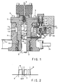
- a cylinder liner 2 is arranged in a pump housing 1, in the bore of which a pump piston 3 is sealingly guided.
- the pump piston 3 is operatively connected at its lower end (not shown in FIG. 1) to a camshaft, through which the pump piston 3 is moved up and down in time with the internal combustion engine.
- the cylinder liner 2 is provided at its upper end with a flange 5, via which the cylinder liner is fastened to the pump housing 1 by means of screws 6.
- a pump chamber 4 is formed in the cylinder liner 2, from which an outlet channel 7, which contains a pressure valve 8, extends. Downstream of the pressure valve 8, a delivery line 9 is connected to the outlet channel 7, which leads to an injection valve (not shown) in the cylinder of the internal combustion engine.
- the pressure valve 8 is pressed by a spring 8 'onto a seat in the outlet channel 7.
- the pump piston 3 has a first control edge 10, which runs partly at right angles, partly at an angle to the piston axis, which has an opening 12 in the wall of the cylinder liner 2 interacts and determines the start of pump delivery.
- the pump piston 3 In the axial direction below the first control edge 10, the pump piston 3 has a second control edge 11, which extends obliquely to the longitudinal axis of the piston, which also cooperates with the opening 12 and which determines the delivery end of the pump.
- the second control edge 11 is formed by a milling in the piston 3, which is delimited towards the lower piston end by an edge 22 running at right angles to the longitudinal axis.
- the cut-out is connected to the pump chamber 4 via a channel 11 ′ extending in the longitudinal direction of the piston.
- the opening 12 extending through the wall of the cylinder liner 2 opens into an annular space 13 which is formed between the cylinder liner and the pump housing 1.
- a suction channel 14 opens into the annular space 13, to which a feed pump (not shown) for the fuel supply is connected.
- an overflow channel 15 is connected to the annular space 13, via which fuel can flow out of the pump space 4 via the channel 11 'and the opening 12 at the end of the delivery phase.
- a channel 16 is provided in the cylinder liner 2, which branches off from the pump chamber 4 at the top and opens into the overflow channel 15 via an overflow valve 17.
- the overflow valve 17 is arranged in the channel 16 in such a way that it is pressed against the seat pressure 18 by the fuel pressure prevailing in the pump chamber 4.
- a spring 17 ' is provided to support this effect.
- the overflow valve 17 is provided on its outflow side with a pin 25 which presses on a spring-loaded piston 31 described below.
- a further opening 28 which penetrates the wall and also penetrates the wall of the pump housing 1 and is connected via a bent tube piece 29 to a space 30 in which the piston 31 abutting the pin 25 is arranged.
- the piston 31 rests on a spring 32 which is supported on the floor of the space 30.
- a bore 33 leads from the space 30 to the overflow duct 15, a spring-loaded refill valve 34 being arranged in this bore.
- This refill valve ensures that, during the delivery stroke of the pump piston 3, the bore 33, the space 30 and the channel leading to the opening 28 cannot be sucked empty, since fuel can flow in from the overflow channel 15 via the refill valve 34 in the event of a negative pressure arising in this volume.
- a bore 35 branches off from the refill valve 34 and also opens into the overflow duct 15 via a control valve 36, namely downstream of the overflow valve 17
- the control valve 36 of which only the closure part is shown in FIG. 1, can be actuated electrically, hydraulically or also mechanically.
- the pump piston 3 has a channel 19 which extends transversely to its longitudinal axis and over part of its circumference, the upper limit of which in FIG. 1 forms a third control edge 20 which interacts with the further opening 28 in the cylinder liner 2.
- the channel 19 communicates with the channel 11 ′ and thus with the pump chamber 4 via an axial channel 21 attached in the outer surface of the piston 3.
- the control edge 20 extends somewhat obliquely to the longitudinal axis of the pump piston 3, which in its lower part in FIG. 1 has a toothing 23 which engages with a toothed rack 24, not shown in detail. With the aid of this rack, the pump piston 3 can be rotated somewhat about its longitudinal axis, so that the position of the three oblique control edges 10, 11 and 20 can be changed relative to the associated openings 12 and 28, respectively.
- the pump piston 3 In normal operation of the device, the pump piston 3 is moved upwards by a cam of the camshaft (not shown) in FIG. 1, the first control edge 10 initially being located some distance from the opening 12. At this time, the pressure valve 8 and the overflow valve 17 are still closed. As soon as the first control edge 10 covers the opening 12 in the further course of the upward movement of the pump piston 3, the delivery phase and thus the injection process begins in that the pump piston 3 presses the fuel in the pump chamber 4 into the delivery line 9 under high pressure, the pressure valve 8 being open is.
- the start of the funding phase is labeled A in FIG. 2.
- the interruption is ended in that the control valve 36 is opened by a corresponding signal, so that the high pressure in the space 30 below the piston 31 is reduced via the bores 33 and 35 and the piston 31 is returned to the position shown in FIG. 1 returns at which the overflow valve 17 is closed.
- This closing point at which the delivery phase is continued via the pressure line 9 to the injection valve, is designated C in FIG. 2.
- the delivery phase or injection is ended when the second control edge 11 releases the opening 12 in the further course of the upward movement of the piston 3, which corresponds to point D in FIG. 2.
- the pressure in the pump chamber 4 builds up via the channel 11 ', the opening 12 and the annular space 13. After the reversal of the movement of the pump piston 3, new fuel reaches the pump chamber 4 via the suction channel 14 and the annular space 13 and the opening 12.
- the opening time of the control valve 36 By varying the opening time of the control valve 36, the time interval between points B and C can be varied, in particular made very small. With the help of the rack 24 it becomes possible to move the entire delivery phase or the entire injection process, i.e. the period between points A and D in Fig. 2, forward or backward, e.g. depending on the load of the internal combustion engine.
Landscapes
- Engineering & Computer Science (AREA)
- Chemical & Material Sciences (AREA)
- Combustion & Propulsion (AREA)
- Mechanical Engineering (AREA)
- General Engineering & Computer Science (AREA)
- Fuel-Injection Apparatus (AREA)
Applications Claiming Priority (2)
| Application Number | Priority Date | Filing Date | Title |
|---|---|---|---|
| CH3719/86A CH670866A5 (da) | 1986-09-17 | 1986-09-17 | |
| CH3719/86 | 1986-09-17 |
Publications (2)
| Publication Number | Publication Date |
|---|---|
| EP0260479A1 EP0260479A1 (de) | 1988-03-23 |
| EP0260479B1 true EP0260479B1 (de) | 1990-11-07 |
Family
ID=4262033
Family Applications (1)
| Application Number | Title | Priority Date | Filing Date |
|---|---|---|---|
| EP87112217A Expired - Lifetime EP0260479B1 (de) | 1986-09-17 | 1987-08-22 | Brennstoffeinspritzvorrichtung für eine Dieselbrennkraftmaschine |
Country Status (6)
| Country | Link |
|---|---|
| EP (1) | EP0260479B1 (da) |
| JP (1) | JP2637993B2 (da) |
| CH (1) | CH670866A5 (da) |
| DE (1) | DE3766058D1 (da) |
| DK (1) | DK166223C (da) |
| FI (1) | FI96055C (da) |
Family Cites Families (5)
| Publication number | Priority date | Publication date | Assignee | Title |
|---|---|---|---|---|
| DE586390C (de) * | 1932-07-23 | 1933-10-20 | Humboldt Deutzmotoren Akt Ges | Brennstoffeinspritzpumpe fuer Brennkraftmaschinen |
| DE738549C (de) * | 1936-10-20 | 1943-08-20 | Bernhard Bischof | Einrichtung zum Einspritzen von Brennstoff bei Brennkraftmaschinen |
| CH290998A (de) * | 1950-05-24 | 1953-05-31 | Cav Ltd | Brennstoffeinspritzpumpe. |
| DE1023637B (de) * | 1953-12-23 | 1958-01-30 | Cav Ltd | Kraftstoffeinspritzpumpe fuer Brennkraftmaschinen |
| CH667900A5 (de) * | 1985-10-18 | 1988-11-15 | Sulzer Ag | Brennstoffeinspritzvorrichtung fuer eine dieselbrennkraftmaschine. |
-
1986
- 1986-09-17 CH CH3719/86A patent/CH670866A5/de not_active IP Right Cessation
-
1987
- 1987-07-09 DK DK357487A patent/DK166223C/da not_active IP Right Cessation
- 1987-08-04 FI FI873386A patent/FI96055C/fi not_active IP Right Cessation
- 1987-08-22 EP EP87112217A patent/EP0260479B1/de not_active Expired - Lifetime
- 1987-08-22 DE DE8787112217T patent/DE3766058D1/de not_active Expired - Lifetime
- 1987-09-16 JP JP62231996A patent/JP2637993B2/ja not_active Expired - Fee Related
Also Published As
| Publication number | Publication date |
|---|---|
| FI873386A7 (fi) | 1988-03-18 |
| DK357487D0 (da) | 1987-07-09 |
| FI96055B (fi) | 1996-01-15 |
| FI96055C (fi) | 1996-04-25 |
| JP2637993B2 (ja) | 1997-08-06 |
| FI873386A0 (fi) | 1987-08-04 |
| JPS6385257A (ja) | 1988-04-15 |
| DE3766058D1 (de) | 1990-12-13 |
| CH670866A5 (da) | 1989-07-14 |
| DK166223C (da) | 1993-08-16 |
| EP0260479A1 (de) | 1988-03-23 |
| DK166223B (da) | 1993-03-22 |
| DK357487A (da) | 1988-03-18 |
Similar Documents
| Publication | Publication Date | Title |
|---|---|---|
| DE2602280C2 (de) | Hochdruck-Kraftstoffeinspritzeinrichtung für Dieselmotoren | |
| DE2558789C2 (da) | ||
| DE2809762C2 (da) | ||
| DE3235413A1 (de) | Brennstoffeinspritzvorrichtung | |
| DE2309916B2 (de) | Kraftstoffeinspritzvorrichtung für Brennkraftmaschinen | |
| EP0150471B1 (de) | Kraftstoffeinspritzpumpe | |
| EP0235569B1 (de) | Einrichtung zum wahlweisen Einspritzen von Dieselöl und Zündöl in den Brennraum einer Dieselöl oder mit Gas als Hauptbrennstoff betriebenen Hubkolbenbrennkraftmaschine | |
| DE3318236C2 (da) | ||
| CH672660A5 (da) | ||
| CH672661A5 (da) | ||
| DE19612721C2 (de) | Speichereinspritzsystem mit Voreinspritzung für eine Brennkraftmaschine | |
| CH671809A5 (da) | ||
| EP0166995A2 (de) | Kraftstoffeinspritzpumpe für Brennkraftmaschinen | |
| WO1987005665A1 (fr) | Pompe a injection de carburant pour moteurs a combustion interne | |
| DE3236828A1 (de) | Brennstoffeinspritzvorrichtung | |
| EP0406592B1 (de) | Kraftstoffeinspritzpumpe | |
| EP0260479B1 (de) | Brennstoffeinspritzvorrichtung für eine Dieselbrennkraftmaschine | |
| DE2240289A1 (de) | Brennstoffeinspritzvorrichtung | |
| AT397129B (de) | Kraftstoffeinspritzdüse | |
| EP0219667B1 (de) | Brennstoffeinspritzvorrichtung für eine Dieselbrennkraftmaschine | |
| DE3538019C2 (da) | ||
| DE1107025B (de) | Kraftstoffeinspritzpumpe mit UEberstroemregelung fuer Brennkraftmaschinen | |
| DE3212052C2 (da) | ||
| DE3915567C2 (de) | Verteil- und Steuerventil einer Kraftstoffeinspritzpumpe | |
| DE3914582A1 (de) | Brennstoffeinspritzvorrichtung |
Legal Events
| Date | Code | Title | Description |
|---|---|---|---|
| PUAI | Public reference made under article 153(3) epc to a published international application that has entered the european phase |
Free format text: ORIGINAL CODE: 0009012 |
|
| AK | Designated contracting states |
Kind code of ref document: A1 Designated state(s): DE FR GB IT NL |
|
| 17P | Request for examination filed |
Effective date: 19880913 |
|
| 17Q | First examination report despatched |
Effective date: 19890328 |
|
| ITF | It: translation for a ep patent filed | ||
| GRAA | (expected) grant |
Free format text: ORIGINAL CODE: 0009210 |
|
| AK | Designated contracting states |
Kind code of ref document: B1 Designated state(s): DE FR GB IT NL |
|
| REF | Corresponds to: |
Ref document number: 3766058 Country of ref document: DE Date of ref document: 19901213 |
|
| ET | Fr: translation filed | ||
| GBT | Gb: translation of ep patent filed (gb section 77(6)(a)/1977) | ||
| PLBE | No opposition filed within time limit |
Free format text: ORIGINAL CODE: 0009261 |
|
| STAA | Information on the status of an ep patent application or granted ep patent |
Free format text: STATUS: NO OPPOSITION FILED WITHIN TIME LIMIT |
|
| 26N | No opposition filed | ||
| PGFP | Annual fee paid to national office [announced via postgrant information from national office to epo] |
Ref country code: GB Payment date: 19920812 Year of fee payment: 6 |
|
| ITTA | It: last paid annual fee | ||
| PG25 | Lapsed in a contracting state [announced via postgrant information from national office to epo] |
Ref country code: GB Effective date: 19930822 |
|
| GBPC | Gb: european patent ceased through non-payment of renewal fee |
Effective date: 19930822 |
|
| PGFP | Annual fee paid to national office [announced via postgrant information from national office to epo] |
Ref country code: NL Payment date: 19990719 Year of fee payment: 13 |
|
| PGFP | Annual fee paid to national office [announced via postgrant information from national office to epo] |
Ref country code: FR Payment date: 19990722 Year of fee payment: 13 |
|
| PG25 | Lapsed in a contracting state [announced via postgrant information from national office to epo] |
Ref country code: NL Free format text: LAPSE BECAUSE OF NON-PAYMENT OF DUE FEES Effective date: 20010301 |
|
| PG25 | Lapsed in a contracting state [announced via postgrant information from national office to epo] |
Ref country code: FR Free format text: LAPSE BECAUSE OF NON-PAYMENT OF DUE FEES Effective date: 20010430 |
|
| NLV4 | Nl: lapsed or anulled due to non-payment of the annual fee |
Effective date: 20010301 |
|
| REG | Reference to a national code |
Ref country code: FR Ref legal event code: ST |
|
| PGFP | Annual fee paid to national office [announced via postgrant information from national office to epo] |
Ref country code: DE Payment date: 20040716 Year of fee payment: 18 |
|
| PG25 | Lapsed in a contracting state [announced via postgrant information from national office to epo] |
Ref country code: IT Free format text: LAPSE BECAUSE OF NON-PAYMENT OF DUE FEES;WARNING: LAPSES OF ITALIAN PATENTS WITH EFFECTIVE DATE BEFORE 2007 MAY HAVE OCCURRED AT ANY TIME BEFORE 2007. THE CORRECT EFFECTIVE DATE MAY BE DIFFERENT FROM THE ONE RECORDED. Effective date: 20050822 |
|
| PG25 | Lapsed in a contracting state [announced via postgrant information from national office to epo] |
Ref country code: DE Free format text: LAPSE BECAUSE OF NON-PAYMENT OF DUE FEES Effective date: 20060301 |