EP0260426B1 - Méthode pour l'obtention des spectres de résonance magnétique nucléaire d'une région localisée sélectivement à l'interieur d'un échantillon étudié - Google Patents
Méthode pour l'obtention des spectres de résonance magnétique nucléaire d'une région localisée sélectivement à l'interieur d'un échantillon étudié Download PDFInfo
- Publication number
- EP0260426B1 EP0260426B1 EP87111354A EP87111354A EP0260426B1 EP 0260426 B1 EP0260426 B1 EP 0260426B1 EP 87111354 A EP87111354 A EP 87111354A EP 87111354 A EP87111354 A EP 87111354A EP 0260426 B1 EP0260426 B1 EP 0260426B1
- Authority
- EP
- European Patent Office
- Prior art keywords
- selective
- pulse
- gradient
- examination
- frequency
- Prior art date
- Legal status (The legal status is an assumption and is not a legal conclusion. Google has not performed a legal analysis and makes no representation as to the accuracy of the status listed.)
- Expired - Lifetime
Links
Images
Classifications
-
- G—PHYSICS
- G01—MEASURING; TESTING
- G01R—MEASURING ELECTRIC VARIABLES; MEASURING MAGNETIC VARIABLES
- G01R33/00—Arrangements or instruments for measuring magnetic variables
- G01R33/20—Arrangements or instruments for measuring magnetic variables involving magnetic resonance
- G01R33/44—Arrangements or instruments for measuring magnetic variables involving magnetic resonance using nuclear magnetic resonance [NMR]
- G01R33/48—NMR imaging systems
- G01R33/483—NMR imaging systems with selection of signals or spectra from particular regions of the volume, e.g. in vivo spectroscopy
- G01R33/4838—NMR imaging systems with selection of signals or spectra from particular regions of the volume, e.g. in vivo spectroscopy using spatially selective suppression or saturation of MR signals
Definitions
- the invention relates to a method for determining nuclear magnetic spectra from spatially selectable examination areas of an examination subject, which is acted upon with a magnetic basic field and a gradient field and with a sequence of RF pulses for excitation of the nuclear magnetic resonance, the resulting nuclear magnetic resonance signal being nearby of the examination area arranged coil is detected and the spatial selection is achieved by superimposing the transmit-receive characteristic of the coil with a selective layer excitation by applying a gradient together with a frequency-selective RF pulse.
- Full spatial resolution is generally not used in nuclear magnetic spectroscopy. However, it is desirable to delimit individual volume areas, for example an organ.
- the desired volume range is selectively excited for this purpose.
- the nuclear magnetic signals are received and also transmitted via a surface coil applied to the body.
- the reception and transmission characteristics of the surface coil are also used for volume selection. Therefore, if a layer is selected for selective excitation by applying a magnetic field gradient, then a section is selected based on the characteristics of the surface coil.
- the known method is problematic for the spectroscopy of compounds with a short relaxation time T2.
- the selective stimulation takes a relatively long time. This results from the fact that an RF pulse with a bandwidth corresponding to the layer thickness must be emitted.
- the FID signal which can only be evaluated after the end of the excitation, has already decayed relatively far at short T2 times. This is especially true for in vivo phosphor spectroscopy.
- the object of the invention is to design a method of the type mentioned at the outset such that the spatially selective spectroscopy can evaluate the unattenuated FID signal.
- This method has the advantage that the readout RF pulse can be kept very short because it is not selective.
- non-selective pulses can have an arbitrarily wide frequency band, which in the time domain corresponds to a period of time that ideally goes towards O.
- the FID signal is thus practically available with its full initial amplitude, so that even cores with a short T2 time can be examined without any problems.
- the volume range to be evaluated can also be limited by selective saturation of several layers. This means that a spatially precisely definable volume range can be delimited.
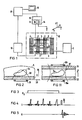
- Figure 1 shows schematically the basic structure of a device for creating spectra of an examination object.
- coils are identified which generate a basic magnetic field B0 in which, when used for medical diagnosis, the body 5 of a patient to be examined is located.
- Gradient coils 7, 8 are assigned, which are provided for generating a magnetic field gradient in the direction y as indicated in FIG. 6.
- the arrangement also contains a whole-body antenna 9 used to generate the nuclear magnetic resonance signals.
- the coils 1, 2, 3, 4, 7, 8 and 9, which are delimited by a dash-dotted line 10, represent the actual examination instrument. It is operated from an electrical arrangement which has a power supply 11 for operating the coils 1 to 4 and a gradient power supply 12, on which the gradient coils 7 and 8 are located.
- a coil (not shown in FIG. 1) for receiving the nuclear magnetic resonance signals is coupled via a signal amplifier 14 to a process computer 17, to which a display device 18 is connected to output the spectrum.
- the whole-body antenna 9 is connected to a high-frequency transmitter 15.
- the components 14 and 15 form a high-frequency device 16 for signal generation and recording.
- FIG. 2 shows a section of the examination object 5.
- An organ 5a which can be the liver, for example, is to be examined spectroscopically.
- the examination object 5 is acted upon by a pulse sequence shown in FIGS. 3 to 5.
- the gradient G y shown in FIG. 3 is switched on in the y direction.
- the layer designated by S in FIG. 2 is then selectively saturated by a sequence of RF pulses of different amplitudes shown in FIG. 4, ie the magnetization previously present due to the basic magnetic field is destroyed within this layer S.
- the full layer S is only saturated, however, if the RF pulses are emitted by the whole-body antenna 9, which covers the entire examination object 5.
- the high-frequency pulses can also be emitted via the surface coil 19 shown schematically in FIG. 2 if this is connected to the RF transmitter 15.
- the examination object 5 is subjected to an RF pulse.
- a surface coil 19 is applied, essentially only the spins in the area OF, otherwise all the spins of the examination object 5 are deflected.
- an FID signal is thus generated, which is shown in FIG. 5.
- This FID signal - again essentially in the OF area - is detected by the surface coil 19 and fed via the signal amplifier 14 to the process computer 17 for evaluation.
- the transmit-receive characteristic of the surface coil 19 is effective in the case of reception in any case, even if the excitation takes place via a whole-body antenna 9.
- the described method of volume selection has the advantage that the non-selective pulse I can be made very short, so that the rapidly decaying FID signal is available with almost its full initial amplitude for the immediately subsequent evaluation.
- the duration of the selective saturation does not interfere with the FID signal and is only limited by the longitudinal relaxation time T 1.
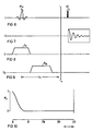
- FIGS. 6 to 9 show a further exemplary embodiment for the selective saturation of the examination area 5a by selective saturation of layers.
- the pulse sequence shown and described below is used n times.
- a frequency-selective high-frequency pulse I n is applied together with a gradient pulse G n .
- G n This rotates the magnetization in the selected layer by an angle ⁇ .
- G sn which creates an artificial inhomogeneity in the magnetic field and thus leads to a dephasing of the spins.
- the transverse magnetization component is first destroyed.
- This pulse sequence is repeated n times with different high-frequency amplitudes and with different orientation and duration of the spoiler gradient. In this way, the desired layers are saturated.
- the saturation sequence can be optimized by varying the amplitudes and the pulse pauses t between two high-frequency pulses I n .
- a value of f 0.9 was recognized as favorable.
- FIG. 10 shows that simultaneous saturation takes place over the entire selected volume range if the original high-frequency pulse has an angle ⁇ of more than 140 °.
- the area OF - as already mentioned - is not clearly delimited.
- the shape of the volume area to be evaluated is not always in harmony with the shape of the area OF specified by the surface coil 19.
- a sharper delimitation of the volume area to be evaluated and flat boundary surfaces thereof are possible if, according to FIG. 11, a further layer S1 parallel to layer S is saturated, so that the volume area to be evaluated within area OF is limited by layers S and S1.
- further selective RF pulses only have to be applied by applying the gradient G y .
- the duration of the saturation is only limited by the relaxation time T 1, while the FID signal remains independent of the duration of the saturation process.
- the T1 relaxation time is relatively long, for example in in-vivo phosphor spectroscopy with a very short T2 relaxation time.
- a Helmholtz coil with two opposite windings 19a and 19b, which includes the examination area 5a, is used, which also has a transmit / receive characteristic, also designated OF.
Claims (4)
- Procédé pour l'obtention de spectres de résonnance magnétique nucléaire dans des régions d'examen (5a) sélectionnées spatialement d'un objet à examiner (5) qui est chargé avec un champ magnétique de base et avec un champ irritationel (Gy) ainsi qu'avec un train d'impulsion HF (J) pour exciter la résonnance magnétique nucléaire, dans lequel le signal de résonnance nucléaire (K) qui se forme est saisi a l'aide d'une bobine (19) qui est disposée dans le voisinage de la région à examiner (1a) et dans lequel la sélection spatiale est obtenue par la superposition de la caractéristique émission-réception de la bobine (2) avec une excitation sélective de la couche par application d'un gradient (Gy) y compris d'une impulsion HF sélective du point de vue de la fréquence, caractérisé par les opérations suivantes :a) on sature sélectivement des portions de volume (S) de l'objet à examiner (5), qui ne sont pas à évaluer,b) on charge l'objet à examiner (5) avec une impulsion de lecture HF non sélective (π/2) qui dévie au moins le spin nucléaire dans les régions à examiner (5a) qui sont à sélectionner, etc) on procéde immédiatement à la suite de l'impulsion de lecture HF non sélective (π/2), à la lecture du signal FID qui se forme.
- Procédé selon la revendication 1, caractérisé par le fait que la région à examiner (5a) qui est à sélectionner, est délimitée par saturation de plusieurs couches (S, S1).
- Procédé selon la revendication 1 ou 2, caractérisé par le fait que la saturation est obtenue par un train (I) d'impulsions HF d'amplitudes différentes et qui sont appliquées en même temps g'un gradient (Gy).
- Procédé selon la revendication 2, caractérisé par le fait que la saturation est obtenue en répétant n fois la séquence impulsionnelle suivant des fréquences :a) une impulsion HF (In) sélective en fréquence est appliquée en même temps qu'un gradient (Gn),b) à la suite de l'impulsion HF (In) sélective en fréquence, on applique un gradient perturbateur (Gsn), la réalisation étant telle que pour chaque séquence d'impulsion, l'amplitude de l'impulsion HF (In) sélective en fréquence et la direction de même que la durée du gradient perturbateur (Gsn) sont modifiées.
Applications Claiming Priority (4)
| Application Number | Priority Date | Filing Date | Title |
|---|---|---|---|
| DE3627939 | 1986-08-18 | ||
| DE3627939 | 1986-08-18 | ||
| DE3711243 | 1987-04-03 | ||
| DE3711243 | 1987-04-03 |
Publications (2)
| Publication Number | Publication Date |
|---|---|
| EP0260426A1 EP0260426A1 (fr) | 1988-03-23 |
| EP0260426B1 true EP0260426B1 (fr) | 1991-04-24 |
Family
ID=25846649
Family Applications (1)
| Application Number | Title | Priority Date | Filing Date |
|---|---|---|---|
| EP87111354A Expired - Lifetime EP0260426B1 (fr) | 1986-08-18 | 1987-08-05 | Méthode pour l'obtention des spectres de résonance magnétique nucléaire d'une région localisée sélectivement à l'interieur d'un échantillon étudié |
Country Status (3)
| Country | Link |
|---|---|
| US (1) | US4816764A (fr) |
| EP (1) | EP0260426B1 (fr) |
| DE (1) | DE3769560D1 (fr) |
Families Citing this family (3)
| Publication number | Priority date | Publication date | Assignee | Title |
|---|---|---|---|---|
| AU590420B2 (en) * | 1986-04-24 | 1989-11-02 | University Of Queensland, The | Volume selected nmr spectroscopy |
| DE4018683A1 (de) * | 1989-06-23 | 1991-01-10 | Siemens Ag | Schichtprofiloptimierung fuer ein mit einer gradientenechosequenz betriebenes kernspin-tomographiegeraet |
| US5467016A (en) * | 1993-04-20 | 1995-11-14 | Siemens Medical Systems, Inc. | Saturation selective spectroscopic imaging |
Family Cites Families (9)
| Publication number | Priority date | Publication date | Assignee | Title |
|---|---|---|---|---|
| US4021726A (en) * | 1974-09-11 | 1977-05-03 | National Research Development Corporation | Image formation using nuclear magnetic resonance |
| US4486708A (en) * | 1981-12-21 | 1984-12-04 | Albert Macovski | Selective material projection imaging system using nuclear magnetic resonance |
| US4471306A (en) * | 1982-02-03 | 1984-09-11 | General Electric Company | Method of NMR imaging which overcomes T2 * effects in an inhomogeneous static magnetic field |
| US4431968A (en) * | 1982-04-05 | 1984-02-14 | General Electric Company | Method of three-dimensional NMR imaging using selective excitation |
| JPS58223048A (ja) * | 1982-06-21 | 1983-12-24 | Toshiba Corp | 磁気共鳴励起領域選択方法、および、該方法が実施し得る磁気共鳴イメージング装置 |
| US4480228A (en) * | 1982-10-15 | 1984-10-30 | General Electric Company | Selective volume method for performing localized NMR spectroscopy |
| US4506223A (en) * | 1982-11-22 | 1985-03-19 | General Electric Company | Method for performing two-dimensional and three-dimensional chemical shift imaging |
| US4629988A (en) * | 1984-07-02 | 1986-12-16 | General Electric Company | Method of imaging by depth-resolved surface coil spectroscopy |
| JPS61102547A (ja) * | 1984-10-25 | 1986-05-21 | Jeol Ltd | 核磁気共鳴装置 |
-
1987
- 1987-08-05 DE DE8787111354T patent/DE3769560D1/de not_active Expired - Fee Related
- 1987-08-05 EP EP87111354A patent/EP0260426B1/fr not_active Expired - Lifetime
-
1988
- 1988-07-08 US US07/218,461 patent/US4816764A/en not_active Expired - Fee Related
Non-Patent Citations (1)
| Title |
|---|
| "ADVANCES IN MAGNETIC RESONANCE" NMR IMAGING IN BIOMEDICINE; SUPPLEMENT 2, P.M. MANSFIELD und P.G. MORRIS, ACADEMIC PRESS, 1982; Seiten 93, 94 * |
Also Published As
| Publication number | Publication date |
|---|---|
| US4816764A (en) | 1989-03-28 |
| EP0260426A1 (fr) | 1988-03-23 |
| DE3769560D1 (de) | 1991-05-29 |
Similar Documents
| Publication | Publication Date | Title |
|---|---|---|
| EP0074022B1 (fr) | Dispositif de tomographie à spin nucléaire | |
| EP0184840B1 (fr) | Arrangement pour l'examen par résolution spatiale d'un échantillon à l'aide de la résonnance magnétique des moments de spin | |
| DE2540436C2 (fr) | ||
| DE102008021736B3 (de) | Verfahren zur Bestimmung der räumlichen Verteilung von Magnetresonanzsignalen beim Einsatz von lokalen ortskodierenden Magnetfeldern | |
| DE3508361A1 (de) | Nmr-spektrometer | |
| DE3517812C2 (fr) | ||
| DE102011083398A1 (de) | Verfahren zur Ansteuerung einer Magnetresonanzanlage | |
| EP0304984B1 (fr) | Analyse spectrale avec sélection de volume utilisant des échos refocalisés | |
| DE4042212A1 (de) | Magnetresonanz-abbildungseinrichtung | |
| DE102005040540A1 (de) | Verfahren und Gerät zur Nachweisverbesserung einer schwachsensitiven Atomkernart in der NMR-Spektroskopie | |
| EP0422170B1 (fr) | Procede d'enregistrement de spectres de resonance de spins | |
| DE3722443A1 (de) | Magnetresonanz-spektroskopiegeraet | |
| EP0412602B1 (fr) | Procédé de spectroscopie RMN et dispositif pour sa mise en oeuvre | |
| EP0199202B1 (fr) | Dispositif de résonance de spin nucléaire | |
| DE4037381C2 (de) | Verfahren zum Anregen einer Probe für die NMR-Tomographie | |
| DE3908392C2 (fr) | ||
| EP1537431A2 (fr) | Procede d'imagerie spectroscopique, dispositif comprenant des moyens pour mettre ce procede en oeuvre et utilisation dudit procede d'imagerie pour caracteriser des materiaux | |
| EP0260426B1 (fr) | Méthode pour l'obtention des spectres de résonance magnétique nucléaire d'une région localisée sélectivement à l'interieur d'un échantillon étudié | |
| EP0278254B1 (fr) | Appareil pour déterminer des spectres de résonance magnétique nucleaire dans des régions spatialement choisies d'un objet examiné | |
| DE3718344A1 (de) | Abbildungsverfahren fuer magnetische kernresonanz | |
| DE4205780C2 (de) | Verfahren zur Erzeugung von NMR-Signalen mit kohärentem Phasenprofil durch Kombination von Hochfrequenzimpulsen mit inkohärentem Phasenprofil | |
| DE10003712A1 (de) | Verfahren zur Selektion einer Lokalantenne | |
| DE3824137C2 (de) | Verfahren zum Betrieb eines Magnetresonanz-Spektroskopiegeräts und Magnetresonanz-Spektroskopiegerät zur Durchführung des Verfahrens | |
| DE19609839A1 (de) | MR-Spektroskopieverfahren | |
| DE3701849A1 (de) | Verfahren und vorrichtung fuer die kernspintomographie |
Legal Events
| Date | Code | Title | Description |
|---|---|---|---|
| PUAI | Public reference made under article 153(3) epc to a published international application that has entered the european phase |
Free format text: ORIGINAL CODE: 0009012 |
|
| AK | Designated contracting states |
Kind code of ref document: A1 Designated state(s): DE FR GB NL |
|
| 17P | Request for examination filed |
Effective date: 19880425 |
|
| 17Q | First examination report despatched |
Effective date: 19890808 |
|
| GRAA | (expected) grant |
Free format text: ORIGINAL CODE: 0009210 |
|
| AK | Designated contracting states |
Kind code of ref document: B1 Designated state(s): DE FR GB NL |
|
| PG25 | Lapsed in a contracting state [announced via postgrant information from national office to epo] |
Ref country code: NL Effective date: 19910424 Ref country code: FR Effective date: 19910424 |
|
| REF | Corresponds to: |
Ref document number: 3769560 Country of ref document: DE Date of ref document: 19910529 |
|
| GBT | Gb: translation of ep patent filed (gb section 77(6)(a)/1977) | ||
| EN | Fr: translation not filed | ||
| NLV1 | Nl: lapsed or annulled due to failure to fulfill the requirements of art. 29p and 29m of the patents act | ||
| PLBE | No opposition filed within time limit |
Free format text: ORIGINAL CODE: 0009261 |
|
| STAA | Information on the status of an ep patent application or granted ep patent |
Free format text: STATUS: NO OPPOSITION FILED WITHIN TIME LIMIT |
|
| 26N | No opposition filed | ||
| PGFP | Annual fee paid to national office [announced via postgrant information from national office to epo] |
Ref country code: GB Payment date: 19930714 Year of fee payment: 7 |
|
| PGFP | Annual fee paid to national office [announced via postgrant information from national office to epo] |
Ref country code: DE Payment date: 19931020 Year of fee payment: 7 |
|
| PG25 | Lapsed in a contracting state [announced via postgrant information from national office to epo] |
Ref country code: GB Effective date: 19940805 |
|
| GBPC | Gb: european patent ceased through non-payment of renewal fee |
Effective date: 19940805 |
|
| PG25 | Lapsed in a contracting state [announced via postgrant information from national office to epo] |
Ref country code: DE Effective date: 19950503 |