EP0260190B1 - Moulds for a prestressing bed - Google Patents
Moulds for a prestressing bed Download PDFInfo
- Publication number
- EP0260190B1 EP0260190B1 EP19870401990 EP87401990A EP0260190B1 EP 0260190 B1 EP0260190 B1 EP 0260190B1 EP 19870401990 EP19870401990 EP 19870401990 EP 87401990 A EP87401990 A EP 87401990A EP 0260190 B1 EP0260190 B1 EP 0260190B1
- Authority
- EP
- European Patent Office
- Prior art keywords
- comb
- module
- bench
- improved device
- prestressing
- Prior art date
- Legal status (The legal status is an assumption and is not a legal conclusion. Google has not performed a legal analysis and makes no representation as to the accuracy of the status listed.)
- Expired - Lifetime
Links
Images

Classifications
-
- B—PERFORMING OPERATIONS; TRANSPORTING
- B28—WORKING CEMENT, CLAY, OR STONE
- B28B—SHAPING CLAY OR OTHER CERAMIC COMPOSITIONS; SHAPING SLAG; SHAPING MIXTURES CONTAINING CEMENTITIOUS MATERIAL, e.g. PLASTER
- B28B7/00—Moulds; Cores; Mandrels
- B28B7/24—Unitary mould structures with a plurality of moulding spaces, e.g. moulds divided into multiple moulding spaces by integratable partitions, mould part structures providing a number of moulding spaces in mutual co-operation
-
- B—PERFORMING OPERATIONS; TRANSPORTING
- B28—WORKING CEMENT, CLAY, OR STONE
- B28B—SHAPING CLAY OR OTHER CERAMIC COMPOSITIONS; SHAPING SLAG; SHAPING MIXTURES CONTAINING CEMENTITIOUS MATERIAL, e.g. PLASTER
- B28B23/00—Arrangements specially adapted for the production of shaped articles with elements wholly or partly embedded in the moulding material; Production of reinforced objects
- B28B23/02—Arrangements specially adapted for the production of shaped articles with elements wholly or partly embedded in the moulding material; Production of reinforced objects wherein the elements are reinforcing members
- B28B23/04—Arrangements specially adapted for the production of shaped articles with elements wholly or partly embedded in the moulding material; Production of reinforced objects wherein the elements are reinforcing members the elements being stressed
- B28B23/043—Wire anchoring or tensioning means for the reinforcements
Description
La technologie de la fabrication des produits allongés en béton précontraint par fils adhérents sur des bancs de précontrainte, tels que poutres, poutrelles, traverses de chemin de fer, a reçu de nombreuses applications et solutions.The technology for manufacturing elongated concrete products prestressed by adherent wires on prestressing benches, such as beams, beams, railway sleepers, has received many applications and solutions.
Dans la fabrication d'éléments en béton précontraint moulé présentant des formes qui risquent lors du relâchement des aciers de précontrainte, en particulier sur grand banc, c'est-à-dire de l'ordre de 80 à 100 m et plus, de solidariser le moule au produit et par la même, d'empêcher le libre glissement des produits béton dans le moule, il est nécessaire d'ouvrir le moule avant relâchement de la tension dans les aciers, pour permettre, par déblocage des éléments béton par rapport au moule, la liberté de mouvement des pièces béton vis à vis des moules.In the manufacture of pre-stressed molded concrete elements having shapes which risk loosening the prestressed steels, in particular on a large bench, that is to say of the order of 80 to 100 m and more, to join the mold to the product and by the same to prevent the free sliding of the concrete products in the mold, it is necessary to open the mold before the tension in the steels is released, to allow, by releasing the concrete elements relative to the mold, the freedom of movement of concrete parts with respect to molds.
Ce déblocage peut être obtenu par des déplacements horizontaux latéraux des flancs de moules comme indiqué dans le brevet français no 78 26898 déposé le 20 septembre 1978 au nom de la demanderesse (FR-A-2436660).This release can be obtained by horizontal lateral movement molds flanks as shown in French Patent No. 78 26898 filed September 20, 1978 on behalf of the applicant (FR-A-2436660).
Dans ce brevet, on décrit un banc de précontrainte pour la fabrication de produits allongés en béton précontraint. Les moules utilisés n'ont plus la longueur du banc, mais sont constitués en modules ou batterie de moules parallèles, de longueurs définies (de l'ordre de 8 à 12 mètres) courtes, relativement à celle du banc (de l'ordre de 80 à 100 mètres) et montés dans un châssis. A titre d'exemple un module peut comporter dix moules parallèles, de mêmes longueurs ,et le banc peut comporter huit modules successifs identiques.In this patent, a prestressing bench for the production of elongated prestressed concrete products is described. The molds used no longer have the length of the bench, but consist of modules or battery of parallel molds, of defined lengths (of the order of 8 to 12 meters) short, relative to that of the bench (of the order of 80 to 100 meters) and mounted in a chassis. By way of example, a module can comprise ten parallel molds, of the same length, and the bench can comprise eight identical successive modules.
Un banc de ce type peut donc comporter un grand nombre de modules successifs ,les moules des modules adjacents étant alignés afin que le même faisceau de fils de précontrainte le traverse successivement.A bench of this type can therefore comprise a large number of successive modules, the molds of the adjacent modules being aligned so that the same bundle of prestressing wires passes through it successively.
Dans cette technique, des flancs de deux moules voisins sont solidaires entre eux, et coulissent dans les deux sens sur un châssis sous l'action de taquets portés par une barre, de sorte qu'un déplacement de cette barre dans un sens ferme tous les moules du module et un déplacement dans un sens opposé ouvre tous lesdits moules.In this technique, the sides of two neighboring molds are integral with each other, and slide in both directions on a frame under the action of cleats carried by a bar, so that a displacement of this bar in a firm direction every module molds and moving in an opposite direction opens all of said molds.
Dans ce brevet, les extrémités des moules sont réalisées sous la forme de blocs de matière élastique comportant les moyens de positionnement des fils.In this patent, the ends of the molds are produced in the form of blocks of elastic material comprising the means for positioning the wires.
Ce dispositif à ouverture et fermeture des moules assure un bon déblocage des éléments en béton vis à vis du moule, cependant il entraîne à chaque déplacement des moules, un déplacement des axes longitudinaux des produits, lors des phases de préparation du coffrage et de l'ouverture des moules, et ce déplacement pose de nouvelles difficultés.This device for opening and closing the molds ensures good release of the concrete elements with respect to the mold, however it causes each displacement of the molds, a displacement of the longitudinal axes of the products, during the phases of preparation of the formwork and the opening of the molds, and this displacement poses new difficulties.
En effet, les fils d'acier sont maintenus aux extrémités du banc dans des chevêtres reliés à des vérins de mise sous tension. Les points de fixation des fils sont immobiles transversalement de sorte qu'ils ne coulissent pas sur le chevêtre avec les déplacements transversaux des moules. De ce fait :
- lors de la préparation des modules, les moules étant ouverts, les axes des fils ne sont pas alignés avec leurs points de fixation sur l'extrémité du banc, ce qui entraîne une grande difficulté pour le centrage et le positionnement des aciers de précontrainte dans le moule, et cela malgré la présence des blocs d'extrémité qui comportent les moyens de positionnement;
- lors de l'ouverture du moule, les aciers tendus dans un axe peuvent empêcher le mouvement d'ouverture du moule.
- during the preparation of the modules, the molds being open, the axes of the wires are not aligned with their fixing points on the end of the bench, which causes great difficulty in centering and positioning the prestressing steels in the mold, and this despite the presence of the end blocks which comprise the positioning means;
- when opening the mold, steels stretched in one axis can prevent the opening movement of the mold.
L'objectif de l'invention est de permettre une immobilisation après mise en place, de la position des aciers de précontrainte relativement aux pièces de béton à fabriquer, quelle que soit la position des flancs de moule de ladite pièce, et de faciliter le déplacement d'ouverture des moules.The objective of the invention is to allow immobilization after installation, of the position of the prestressing steels relative to the concrete parts to be manufactured, regardless of the position of the mold sides of said part, and to facilitate movement opening the molds.
L'invention a pour objet un dispositif perfectionné de banc de précontrainte pour la fabrication de produits allongés comportant au moins un module de moules ouvrables, parallèles entre eux, les flancs des moules étant montés solidaires entre eux sur une plaque longitudinale glissant sur un châssis sous l'action d'une barre de déplacement, comportant de chaque côté du module, des rives , dont une au moins est fixe , et comportant des fils de précontrainte fixés sur les chevêtres d'extrémité de bancs, caractérisé en ce qu'au moins un module d'extrémité du banc comporte entre le chevêtre et l'extrémité du module le plus proche, un peigne , rigide, d'une longueur égale au moins à la largeur du module , coopérant avec la barre de déplacement des flancs de moules, muni de fentes verticales de passage et positionnement des fils de précontrainte , monté pivotant horizontalement entre le chevêtre et le module , l'articulation étant disposée dans le prolongement de la rive fixe du module.The invention relates to an improved device for prestressing bench for the production of elongated products comprising at least one module of opening molds, parallel to each other, the sides of the molds being mounted integral with each other on a longitudinal plate sliding on a chassis under the action of a displacement bar, comprising on each side of the module, edges, at least one of which is fixed, and comprising prestressing wires fixed on the end caps of benches, characterized in that at least an end module of the bench comprises, between the trimmer and the end of the nearest module, a rigid comb, of a length equal at least to the width of the module, cooperating with the displacement bar of the sides of the molds, provided with vertical slots for passage and positioning of the prestressing wires, mounted to pivot horizontally between the trimmer and the module, the articulation being arranged in the extension of e the fixed edge of the module.
De préférence :
- le peigne comporte à son extrémité opposée à l'articulation un dispositif de liaison coopérant avec un bras d'extension de la rive d'extrémité longitudinale mobile, permettant de coordonner la rotation du peigne au déplacement de la rive , et des flancs de moules dans un sens ou dans le sens opposé;
- le dispositif de liaison est un passage pratiqué dans le peigne, muni de galets de roulement coopérant avec une plage de roulement du bras ;
- l'extrémité du peigne est reliée à l'extrémité du banc par un vérin de rappel et poussée.
- the comb comprises at its end opposite the articulation a connecting device cooperating with an extension arm of the movable longitudinal end edge, making it possible to coordinate the rotation of the comb when the shore moves, and the sides of the molds in one direction or in the opposite direction;
- the connecting device is a passage made in the comb, provided with rollers cooperating with a bearing range of the arm;
- the end of the comb is connected to the end of the bench by a return and push cylinder.
L'invention est illustrée au dessin annexé sur lequel :The invention is illustrated in the appended drawing in which:
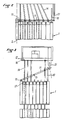
La figure 1 est une vue en perspective du dispositif perfectionné du banc de précontrainte selon l'invention;Figure 1 is a perspective view of the improved device of the prestressing bench according to the invention;
La figure 2 est une vue schématique de dessus du dispositif perfectionné de banc de précontrainte selon l'invention en position de moules ouverts ;Figure 2 is a schematic top view of the improved device of prestressing bench according to the invention in the open mold position;
La figure 3 est une vue schématique selon la figure 1 du dispositif selon l'invention en position de moules fermés.Figure 3 is a schematic view according to Figure 1 of the device according to the invention in the closed mold position.
La figure 1 montre en perspective un module 1 d'extrémité de banc de précontrainte. Le banc n'est pas représenté en entier mais peut atteindre de grandes longueurs, par exemple 80 à 100 mètres et plus, et comporte une pluralité de modules 1, 1ʹ en série les uns derrière les autres.Figure 1 shows in perspective a module 1 end of prestressing bench. The bench is not shown in its entirety but can reach great lengths, for example 80 to 100 meters and more, and comprises a plurality of modules 1, 1ʹ in series one behind the other.
Ce module 1 est constitué d'un ensemble de moules 4 disposés en batterie sur un châssis 3 , parallèlement les uns les autres selon l'axe longitudinal 2 du banc de précontrainte. Chaque moule 4 est constitué de deux flancs 5 et 6, mobiles transversalement, et les flancs 6, 5ʹ de deux moules voisins 4, 4ʹ sont montés solidaires entre eux comme décrit par exemple dans le brevet no 78.26898.This module 1 consists of a set of molds 4 arranged in a battery on a
Le module comporte des rives longitudinales 8, 9 dont une au moins, dite "rive d'origine" 8, est fixe et solidaire du châssis.The module has
Selon l'invention, on dispose entre le module d'extrémité 1, et plus précisément entre l'extrémité des moules et le chevêtre 12 de fixation des fils 14 un peigne 11, articulé sur l'extrémité de la rive d'origine 8 immobile ; de sorte qu'il pivote horizontalement dans l'espace situé entre le module et le chevêtre 12. Il comporte des fentes 13 verticales prévues pour le passage et le positionnement des fils 14 de précontrainte, comme indiqué sur les figures. Ainsi la rotation du peinge 11 autour de son axe 15 s'accompagne d'un déplacement des fentes transversalement par rapport à l'axe longitudinal 2.According to the invention, there is between the end module 1, and more precisely between the end of the molds and the
Lorsque le peigne pivote vers le module, les fentes 13 se déplacent et s'écartent de la rive 8 fixe, et l'espacement entre les fentes 13 selon la projection transversale à l'axe longitudinal 2 augmente. La position d'écartement maximum et l'espacement maximum entre les fentes 13 sont atteints lorsque le peigne est perpendiculaire à l'axe 2 du module, contre les blocs d'extrémité 17 des moules. Ce déplacement s'accompagne d'un écartement des fils 14 les uns des autres dans le module 1. La rotation du peigne est coordonnée au dispositif d'ouverture et fermeture des moules décrit au brevet 78.26898, de sorte que la rotation du peigne coopère au déplacement des flancs 5, 6, de moule : le sens du déplacement des moules et des pièces en béton s'accompagne toujours du même sens de déplacement des fentes. En outre la valeur du déplacement des moules est proportionnelle à celle du déplacement des pièces en béton, afin que
- 1) l'écartement des fils 14 s'accompagne d'un écartement correspondant des pièces respectives ;
- 2) les fils de précontrainte 14, en sortie des fentes 11 soient toujours centrés centrés sur leurs pièces respectives.
- 1) the spacing of the
wires 14 is accompanied by a corresponding spacing of the respective parts; - 2) the
prestressing wires 14, at the outlet from theslots 11 are always centered centered on their respective parts.
Conformément à l'invention, le peigne 11 comporte des moyens de commande du pivotement. Selon l'exemple illustré sur la figure 3, la rive 9 dite rive d'extrémité, opposée à la rive d'origine 8 fixe, est mobile transversalement suivant le même mouvement que les autres flancs de moule.According to the invention, the
Le peigne 11 à son extrémité 18 opposée à l'articulation, comporte un passage de section transversale verticale, muni d'un moyen 19 de roulement, par exemple des galets de roulement, et ce passage est destiné à recevoir une extension 10 longitudinale de la rive 9 , en forme de bras sensiblement rectiligne, orienté vers l'extrémité du banc, et muni d'une plage de roulement 20.The
Ce passage assure ainsi une liaison mobile entre le peigne 11 et la rive 9. Lorsque la rive 9 est déplacée dans un sens par le dispositif de commande de déplacement des flancs de moule, elle entraîne la rotation du peigne dans un sens, et lorsque la rive est déplacée dans le sens opposé, elle entraîne la rotation du peigne en sens opposé.This passage thus ensures a movable connection between the
En outre, il est possible de favoriser le mouvement de rotation du peigne en reliant l'extrémité du peigne à l'extrémité fixe du banc par tout moyen de rappel par exemple par un ressort ou un vérin 21.Furthermore, it is possible to promote the rotational movement of the comb by connecting the end of the comb to the fixed end of the bench by any return means, for example by a spring or a
Dans une variante de réalisation, la rive mobile 9 ne comporte pas d'extension. Dans ce cas, l'extrémité 18 du peigne est reliée à l'extrémité du banc par un vérin dont l'action est coordonnée au dispositif de commande du déplacement des flancs de moule.In an alternative embodiment, the movable edge 9 has no extension. In this case, the
Le dispositif perfectionné selon l'invention peut être disposé soit à chaque extrémité du banc de précontrainte soit à une seule extrémité, soit encore jumelé comme illustré sur la figure 3.The improved device according to the invention can be arranged either at each end of the prestressing bench or at a single end, or even twinned as illustrated in FIG. 3.
De préférence, le peigne est en métal, fabriqué dans un profil d'acier en I, ou H.Preferably, the comb is made of metal, made from an I, or H steel profile.
Par ailleurs, quelle que soit la variante de réalisation la mise en tension des aciers de précontrainte est effectuée avec le moule ferméFurthermore, whatever the variant, the tensioning of the prestressing steels is carried out with the mold closed.
Claims (6)
- An improved device for a prestressing bench for the manufacturing of elongated products, comprising at least one module of openable moulds parallel to each other, the flanks of the modules being mounted integrally together on a longitudinal plate which is slidable along a frame under the action of a displacer bar, comprising on each side of the module edgings (8, 9), at least one of which is fixed, and comprising prestressing wires fixed onto the trimmer beams on both ends of the bench,
characterized in that at least one module (1) on one end of the bench comprises, between the trimmer beam (12) and the end of the nearest module (1), a rigid comb (11) having a length at least equal to the width of the module (1), cooperating with the displacer bar provided for displacing the flanks of the moulds, said comb being provided with slots (13) for the passage and positioning of the prestressing wires (14) and being swivable horizontally between the trimmer beam (12) and the module (1), the articulation (15) being disposed in the extension of the fixed edging (8) of the module. - An improved device according to Claim 1, characterized in that the comb (11) comprises on its end (18) opposite to the articulation (15) a linkage device cooperating with an arm (10) forming an extension of the movable longitudinal end edging (9), making it possible to coordinate the swivelling of the comb (11) with the displacement of the edging (9) and of the flanks (5, 6, 5') of the moulds in one given direction or in the opposite direction.
- An improved device according to Claim 2, characterized in that the linkage device is a passage formed in the comb, provided with rollers (19) cooperating with a rolling surface (20) of the arm (10).
- An improved device according to Claim 2, characterized in that the end (18) of the comb is connected to the end of the bench through a jack (21) for returning and pushing said comb.
- An improved device according to any one of the preceding Claims, characterized in that each end module comprises a comb (11) in accordance with the invention.
- An improved device according to any one of the preceding Claims, characterized in that the comb (11) according to the invention is disposed in twinned arrangement with another comb, symmetrically about the longitudinal axis (2) of the module (1).
Applications Claiming Priority (2)
| Application Number | Priority Date | Filing Date | Title |
|---|---|---|---|
| FR8612546 | 1986-09-08 | ||
| FR8612546A FR2603515B1 (en) | 1986-09-08 | 1986-09-08 | IMPROVEMENT IN MOLDS FOR PRESSURE BENCH |
Publications (3)
| Publication Number | Publication Date |
|---|---|
| EP0260190A2 EP0260190A2 (en) | 1988-03-16 |
| EP0260190A3 EP0260190A3 (en) | 1989-09-27 |
| EP0260190B1 true EP0260190B1 (en) | 1991-04-24 |
Family
ID=9338764
Family Applications (1)
| Application Number | Title | Priority Date | Filing Date |
|---|---|---|---|
| EP19870401990 Expired - Lifetime EP0260190B1 (en) | 1986-09-08 | 1987-09-04 | Moulds for a prestressing bed |
Country Status (2)
| Country | Link |
|---|---|
| EP (1) | EP0260190B1 (en) |
| FR (1) | FR2603515B1 (en) |
Families Citing this family (1)
| Publication number | Priority date | Publication date | Assignee | Title |
|---|---|---|---|---|
| RU2682832C1 (en) * | 2018-03-06 | 2019-03-21 | Федеральное государственное бюджетное образовательное учреждение высшего образования "Тамбовский государственный технический университет" (ФГБОУ ВО "ТГТУ") | Pallet for manufacture of bolt with thermal inserts of frame of prefabricated monolithic building |
Family Cites Families (3)
| Publication number | Priority date | Publication date | Assignee | Title |
|---|---|---|---|---|
| FR914905A (en) * | 1945-04-23 | 1946-10-22 | Joists for reinforced concrete floors and their method of manufacture | |
| US3084910A (en) * | 1960-04-29 | 1963-04-09 | William D Allers | Apparatus for forming prestressed concrete sheets |
| US4084928A (en) * | 1976-11-03 | 1978-04-18 | Cmi Corporation | Slip form having reinforcement accommodating means |
-
1986
- 1986-09-08 FR FR8612546A patent/FR2603515B1/en not_active Expired - Fee Related
-
1987
- 1987-09-04 EP EP19870401990 patent/EP0260190B1/en not_active Expired - Lifetime
Also Published As
| Publication number | Publication date |
|---|---|
| FR2603515B1 (en) | 1990-07-27 |
| FR2603515A1 (en) | 1988-03-11 |
| EP0260190A3 (en) | 1989-09-27 |
| EP0260190A2 (en) | 1988-03-16 |
Similar Documents
| Publication | Publication Date | Title |
|---|---|---|
| EP0778169B1 (en) | Tarpaulin arrangement for lorries | |
| FR2480638A1 (en) | CONVEYOR FOR TRANSFERRING PARTS OUTSIDE A PRESSURE MOLDING MACHINE | |
| CA1119887A (en) | Adjustment means for the alignment and the gapping of two abutted rail sections | |
| CH618371A5 (en) | ||
| FR2618198A1 (en) | DEVICE FOR ANTIVIBRATORY SETTING OF COMPONENTS OF A SYSTEM AND IN PARTICULAR ANTIVIBRATORY SETTING BARS FOR TUBES OF A STEAM GENERATOR. | |
| FR2482714A1 (en) | GLACIERE WITH VERTICAL PLATES | |
| FR2617744A1 (en) | METHOD AND INSTALLATION FOR PLANTING A METAL STRIP | |
| EP0260190B1 (en) | Moulds for a prestressing bed | |
| CH632027A5 (en) | RAILER OF RAILWAYS. | |
| WO1989006578A1 (en) | Method and device for projecting a coating to the internal surface of a liquid metal pouring container | |
| WO2004000479A1 (en) | Guide support for a tube-bending machine | |
| FR2525526A1 (en) | MACHINE FOR MOLDING SYNTHETIC MATERIALS BY INJECTION | |
| CH619656A5 (en) | Handling device comprising an overhead track | |
| FR2734289A1 (en) | METHOD FOR MOVING A WALL WITH ARTICULATED MODULES AND MACHINE AND DEVICE FOR CARRYING OUT SAID METHOD | |
| FR2883591A1 (en) | Comb-like split formwork for reinforced concrete beam end, has teeth with pivoting bars revealing slits, and front sides having crenated contour forming orifices between them for passage and positioning of beam`s longitudinal reinforcements | |
| FR2531743A1 (en) | BUCKET MECHANISM FOR THE ADVANCE OF A SLAUGHTER, ESPECIALLY FOR A DRUM HARVESTER | |
| FR2698856A1 (en) | Cable guiding device for a winch, in particular a hoisting winch. | |
| FR2657547A1 (en) | Device for the manufacture of metal workpieces in the form of a stirrup (portal frame) which possesses a double curvature | |
| FR2729879A1 (en) | METHOD AND APPARATUS FOR SPOT WELDING FOR THE ASSEMBLY OF A BEAM BOX OF A CRANE | |
| BE713824A (en) | ||
| FR2969939A3 (en) | Cutting tool for severing metallic U-shaped cross-sectional profiles utilized as e.g. building elements, has support comprising recess that is opened towards top to transversally receive profile with respect to cutting plane | |
| FR2464174A1 (en) | Track for earthmoving vehicle - has inverted U-shaped support on chassis to guide lower length of chain carrying overlapping plates | |
| FR2696628A1 (en) | Framework fixing window box to balustrade - has upper hooks hooking over balustrade and lower hooks holding window box, and slightly elastic rods fitting over bars of framework | |
| FR2613747A1 (en) | Crosspiece with movable and orientable bearing points for forming shuttering panels, and shuttering panels made by means of this crosspiece | |
| FR2793826A1 (en) | CONSTRUCTION BLOCK FOR THE REALIZATION OF A CORNER OF A BUILDING WALL |
Legal Events
| Date | Code | Title | Description |
|---|---|---|---|
| PUAI | Public reference made under article 153(3) epc to a published international application that has entered the european phase |
Free format text: ORIGINAL CODE: 0009012 |
|
| AK | Designated contracting states |
Kind code of ref document: A2 Designated state(s): BE LU NL |
|
| 17P | Request for examination filed |
Effective date: 19880308 |
|
| PUAL | Search report despatched |
Free format text: ORIGINAL CODE: 0009013 |
|
| AK | Designated contracting states |
Kind code of ref document: A3 Designated state(s): BE LU NL |
|
| 17Q | First examination report despatched |
Effective date: 19900709 |
|
| RAP1 | Party data changed (applicant data changed or rights of an application transferred) |
Owner name: RECTOR S.A. |
|
| RAP3 | Party data changed (applicant data changed or rights of an application transferred) |
Owner name: RECTOR S.A. |
|
| GRAA | (expected) grant |
Free format text: ORIGINAL CODE: 0009210 |
|
| AK | Designated contracting states |
Kind code of ref document: B1 Designated state(s): BE LU NL |
|
| PG25 | Lapsed in a contracting state [announced via postgrant information from national office to epo] |
Ref country code: NL Effective date: 19910424 |
|
| NLV1 | Nl: lapsed or annulled due to failure to fulfill the requirements of art. 29p and 29m of the patents act | ||
| PLBE | No opposition filed within time limit |
Free format text: ORIGINAL CODE: 0009261 |
|
| STAA | Information on the status of an ep patent application or granted ep patent |
Free format text: STATUS: NO OPPOSITION FILED WITHIN TIME LIMIT |
|
| 26N | No opposition filed | ||
| EPTA | Lu: last paid annual fee | ||
| PGFP | Annual fee paid to national office [announced via postgrant information from national office to epo] |
Ref country code: LU Payment date: 19940901 Year of fee payment: 8 |
|
| PGFP | Annual fee paid to national office [announced via postgrant information from national office to epo] |
Ref country code: BE Payment date: 19940914 Year of fee payment: 8 |
|
| PG25 | Lapsed in a contracting state [announced via postgrant information from national office to epo] |
Ref country code: LU Free format text: LAPSE BECAUSE OF NON-PAYMENT OF DUE FEES Effective date: 19950904 |
|
| PG25 | Lapsed in a contracting state [announced via postgrant information from national office to epo] |
Ref country code: BE Effective date: 19950930 |
|
| BERE | Be: lapsed |
Owner name: S.A. RECTOR Effective date: 19950930 |