EP0260190B1 - Formen für eine Spannbettanlage - Google Patents
Formen für eine Spannbettanlage Download PDFInfo
- Publication number
- EP0260190B1 EP0260190B1 EP19870401990 EP87401990A EP0260190B1 EP 0260190 B1 EP0260190 B1 EP 0260190B1 EP 19870401990 EP19870401990 EP 19870401990 EP 87401990 A EP87401990 A EP 87401990A EP 0260190 B1 EP0260190 B1 EP 0260190B1
- Authority
- EP
- European Patent Office
- Prior art keywords
- comb
- module
- bench
- improved device
- prestressing
- Prior art date
- Legal status (The legal status is an assumption and is not a legal conclusion. Google has not performed a legal analysis and makes no representation as to the accuracy of the status listed.)
- Expired - Lifetime
Links
- 238000006073 displacement reaction Methods 0.000 claims description 12
- 238000004519 manufacturing process Methods 0.000 claims description 5
- 238000005096 rolling process Methods 0.000 claims description 3
- 238000007688 edging Methods 0.000 claims 4
- 239000004567 concrete Substances 0.000 description 9
- 229910000831 Steel Inorganic materials 0.000 description 8
- 239000010959 steel Substances 0.000 description 8
- 238000002360 preparation method Methods 0.000 description 2
- 230000001464 adherent effect Effects 0.000 description 1
- 239000013013 elastic material Substances 0.000 description 1
- 238000009415 formwork Methods 0.000 description 1
- 238000009434 installation Methods 0.000 description 1
- 239000002184 metal Substances 0.000 description 1
- 238000000034 method Methods 0.000 description 1
- 239000011513 prestressed concrete Substances 0.000 description 1
Images

Classifications
-
- B—PERFORMING OPERATIONS; TRANSPORTING
- B28—WORKING CEMENT, CLAY, OR STONE
- B28B—SHAPING CLAY OR OTHER CERAMIC COMPOSITIONS; SHAPING SLAG; SHAPING MIXTURES CONTAINING CEMENTITIOUS MATERIAL, e.g. PLASTER
- B28B7/00—Moulds; Cores; Mandrels
- B28B7/24—Unitary mould structures with a plurality of moulding spaces, e.g. moulds divided into multiple moulding spaces by integratable partitions, mould part structures providing a number of moulding spaces in mutual co-operation
-
- B—PERFORMING OPERATIONS; TRANSPORTING
- B28—WORKING CEMENT, CLAY, OR STONE
- B28B—SHAPING CLAY OR OTHER CERAMIC COMPOSITIONS; SHAPING SLAG; SHAPING MIXTURES CONTAINING CEMENTITIOUS MATERIAL, e.g. PLASTER
- B28B23/00—Arrangements specially adapted for the production of shaped articles with elements wholly or partly embedded in the moulding material; Production of reinforced objects
- B28B23/02—Arrangements specially adapted for the production of shaped articles with elements wholly or partly embedded in the moulding material; Production of reinforced objects wherein the elements are reinforcing members
- B28B23/04—Arrangements specially adapted for the production of shaped articles with elements wholly or partly embedded in the moulding material; Production of reinforced objects wherein the elements are reinforcing members the elements being stressed
- B28B23/043—Wire anchoring or tensioning means for the reinforcements
Definitions
- a prestressing bench for the production of elongated prestressed concrete products.
- the molds used no longer have the length of the bench, but consist of modules or battery of parallel molds, of defined lengths (of the order of 8 to 12 meters) short, relative to that of the bench (of the order of 80 to 100 meters) and mounted in a chassis.
- a module can comprise ten parallel molds, of the same length, and the bench can comprise eight identical successive modules.
- a bench of this type can therefore comprise a large number of successive modules, the molds of the adjacent modules being aligned so that the same bundle of prestressing wires passes through it successively.
- the sides of two neighboring molds are integral with each other, and slide in both directions on a frame under the action of cleats carried by a bar, so that a displacement of this bar in a firm direction every module molds and moving in an opposite direction opens all of said molds.
- the ends of the molds are produced in the form of blocks of elastic material comprising the means for positioning the wires.
- This device for opening and closing the molds ensures good release of the concrete elements with respect to the mold, however it causes each displacement of the molds, a displacement of the longitudinal axes of the products, during the phases of preparation of the formwork and the opening of the molds, and this displacement poses new difficulties.
- the objective of the invention is to allow immobilization after installation, of the position of the prestressing steels relative to the concrete parts to be manufactured, regardless of the position of the mold sides of said part, and to facilitate movement opening the molds.
- the invention relates to an improved device for prestressing bench for the production of elongated products
- a module of opening molds parallel to each other, the sides of the molds being mounted integral with each other on a longitudinal plate sliding on a chassis under the action of a displacement bar, comprising on each side of the module, edges, at least one of which is fixed, and comprising prestressing wires fixed on the end caps of benches, characterized in that at least an end module of the bench comprises, between the trimmer and the end of the nearest module, a rigid comb, of a length equal at least to the width of the module, cooperating with the displacement bar of the sides of the molds, provided with vertical slots for passage and positioning of the prestressing wires, mounted to pivot horizontally between the trimmer and the module, the articulation being arranged in the extension of e the fixed edge of the module.
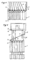
- Figure 1 is a perspective view of the improved device of the prestressing bench according to the invention.
- Figure 2 is a schematic top view of the improved device of prestressing bench according to the invention in the open mold position;
- Figure 3 is a schematic view according to Figure 1 of the device according to the invention in the closed mold position.
- Figure 1 shows in perspective a module 1 end of prestressing bench.
- the bench is not shown in its entirety but can reach great lengths, for example 80 to 100 meters and more, and comprises a plurality of modules 1, 1 ⁇ in series one behind the other.
- This module 1 consists of a set of molds 4 arranged in a battery on a chassis 3, parallel to each other along the longitudinal axis 2 of the prestressing bench.
- Each mold 4 consists of two sidewalls 5 and 6, movable transversely, and the flanks 6, 5 'of two adjacent molds 4, 4'are mounted integral with each other as described for example in patent No. 78.26898.
- the module has longitudinal edges 8, 9 of which at least one, called the "original bank" 8, is fixed and integral with the chassis.
- the end module 1 there is between the end module 1, and more precisely between the end of the molds and the trimmer 12 for fixing the wires 14, a comb 11, articulated on the end of the stationary bank of origin 8 ; so that it pivots horizontally in the space between the module and the header 12. It has vertical slots 13 provided for the passage and positioning of the prestressing wires 14, as indicated in the figures.
- the rotation of the peinge 11 around its axis 15 is accompanied by a displacement of the slots transversely with respect to the longitudinal axis 2.
- the comb 11 comprises means for controlling the pivoting.
- the bank 9 said end bank, opposite the original bank 8 fixed, is transversely movable in the same movement as the other mold sides.
- the comb 11 at its end 18 opposite the articulation comprises a passage of vertical cross section, provided with a rolling means 19, for example rolling rollers, and this passage is intended to receive a longitudinal extension 10 of the bank 9, in the form of a substantially rectilinear arm, oriented towards the end of the bench, and provided with a bearing surface 20.
- This passage thus ensures a movable connection between the comb 11 and the bank 9.
- the bank 9 When the bank 9 is moved in one direction by the device for controlling the movement of the mold flanks, it causes the comb to rotate in one direction, and when the shore is moved in the opposite direction, it causes the comb to rotate in the opposite direction.
- the movable edge 9 has no extension.
- the end 18 of the comb is connected to the end of the bench by a jack whose action is coordinated with the device for controlling the movement of the mold flanks.
- the improved device according to the invention can be arranged either at each end of the prestressing bench or at a single end, or even twinned as illustrated in FIG. 3.
- the comb is made of metal, made from an I, or H steel profile.
Landscapes
- Engineering & Computer Science (AREA)
- Manufacturing & Machinery (AREA)
- Chemical & Material Sciences (AREA)
- Ceramic Engineering (AREA)
- Mechanical Engineering (AREA)
- Moulds, Cores, Or Mandrels (AREA)
- Moulds For Moulding Plastics Or The Like (AREA)
Claims (6)
- Weiterentwickelte Spannbettanlage zur Herstellung von Langerzeugnissen mit zumindest einem Modul zu öffnender, parallel zueinander stehender Formen, deren, unter Einwirkung einer Schubstange auf einem Rahmen gleitende Wände fest miteinander auf einer länglichen Platte montiert sind, mit Seitenteilen (8, 9) auf beiden Seiten des Moduls, von denen zumindest einer feststehend ist, und mit auf Wechselbalken am Spannbettende befestigten Spannbetondrähten, dadurch gekennzeichnet, daß zumindest ein Spannbett-Endmodul (1) zwischen dem Wechselbalken (12) und dem nächstliegenden Modulende (1) einen starren Kamm (11) besitzt, der mindestens so lang wie das Modul (1) breit ist, der mit der Formenwand-Schubstange zusammenwirkt, senkrechte Durchlaßschlitze (13) zur Positionierung der Spannbetondrähte (14) aufweist und eine waagrechte Schwenkbefestigung zwischen Wechselbalken (12) und Modul (1) besitzt, wobei das Gelenk (15) in der Verlängerung des festen Modulseitenteils (8) liegt.
- Weiterentwickelte Anlage nach Anspruch 1, dadurch gekennzeichnet, daß der Kamm (11) an seinem dem Gelenk (15) gegenüberliegenden Ende (18) eine mit einem Verlängerungsarm (10) zusammenwirkende Verbindung am beweglichen Längsseitenteil (9) zur Koordinierung der Kammdrehung (11) bei Verschiebung des Seitenteils (9) und der Formenwände (5, 6, 5') in der einen oder anderen Richtung aufweist.
- Weiterentwickelte Anlage nach Anspruch 2, dadurch gekennzeichnet, daß die Verbindung aus einem im Kamm vorgesehenen Durchlaß mit Laufrollen (19) besteht, die mit einer Lauffläche (20) des Arms (10) zusammenwirken.
- Weiterentwickelte Anlage nach Anspruch 2, dadurch gekennzeichnet, daß das Kammende (18) durch einen Rückzugund Schubzylinder (21) mit dem Spannbettende verbunden ist.
- Weiterentwickelte Anlage nach einem der Ansprüche 1 bis 4, dadurch gekennzeichnet, daß jedes Endmodul einen Kamm (11) laut Erfindung aufweist.
- Weiterentwickelte Anlage nach einem der Ansprüche 1 bis 5, dadurch gekennzeichnet, daß der Kamm (11) laut Erfindung mit einem weiteren Kamm symmetrisch zur Achse (2) des Moduls (1) gepaart ist.
Applications Claiming Priority (2)
| Application Number | Priority Date | Filing Date | Title |
|---|---|---|---|
| FR8612546A FR2603515B1 (fr) | 1986-09-08 | 1986-09-08 | Perfectionnement aux moules pour banc de precontrainte |
| FR8612546 | 1986-09-08 |
Publications (3)
| Publication Number | Publication Date |
|---|---|
| EP0260190A2 EP0260190A2 (de) | 1988-03-16 |
| EP0260190A3 EP0260190A3 (en) | 1989-09-27 |
| EP0260190B1 true EP0260190B1 (de) | 1991-04-24 |
Family
ID=9338764
Family Applications (1)
| Application Number | Title | Priority Date | Filing Date |
|---|---|---|---|
| EP19870401990 Expired - Lifetime EP0260190B1 (de) | 1986-09-08 | 1987-09-04 | Formen für eine Spannbettanlage |
Country Status (2)
| Country | Link |
|---|---|
| EP (1) | EP0260190B1 (de) |
| FR (1) | FR2603515B1 (de) |
Families Citing this family (2)
| Publication number | Priority date | Publication date | Assignee | Title |
|---|---|---|---|---|
| RU2121920C1 (ru) * | 1997-04-23 | 1998-11-20 | Виктор Аршакович Кеворков | Завод железобетонных изделий |
| RU2682832C1 (ru) * | 2018-03-06 | 2019-03-21 | Федеральное государственное бюджетное образовательное учреждение высшего образования "Тамбовский государственный технический университет" (ФГБОУ ВО "ТГТУ") | Поддон для изготовления ригеля с термовкладышами каркаса сборно-монолитного здания |
Family Cites Families (3)
| Publication number | Priority date | Publication date | Assignee | Title |
|---|---|---|---|---|
| FR914905A (fr) * | 1945-04-23 | 1946-10-22 | Solives pour planchers en béton armé et leur mode de fabrication | |
| US3084910A (en) * | 1960-04-29 | 1963-04-09 | William D Allers | Apparatus for forming prestressed concrete sheets |
| US4084928A (en) * | 1976-11-03 | 1978-04-18 | Cmi Corporation | Slip form having reinforcement accommodating means |
-
1986
- 1986-09-08 FR FR8612546A patent/FR2603515B1/fr not_active Expired - Fee Related
-
1987
- 1987-09-04 EP EP19870401990 patent/EP0260190B1/de not_active Expired - Lifetime
Also Published As
| Publication number | Publication date |
|---|---|
| FR2603515B1 (fr) | 1990-07-27 |
| EP0260190A2 (de) | 1988-03-16 |
| FR2603515A1 (fr) | 1988-03-11 |
| EP0260190A3 (en) | 1989-09-27 |
Similar Documents
| Publication | Publication Date | Title |
|---|---|---|
| EP0778169B1 (de) | Lastkraftwagen-Planenabdeckungs-Vorrichtung | |
| CA1119887A (fr) | Dispositif de reglage de l'alignement et de la distance intercalaire de deux abouts de rails | |
| CH618371A5 (de) | ||
| FR2617744A1 (fr) | Procede et installation de planage d'une bande metallique | |
| EP0260190B1 (de) | Formen für eine Spannbettanlage | |
| FR2482714A1 (fr) | Glaciere a plaques verticales | |
| CH632027A5 (fr) | Bourreuse de voies ferrees. | |
| FR2488578A1 (fr) | Supports lateraux de plaques superieures d'une fleche de grue | |
| EP0446130B1 (de) | Anlage zum Richten | |
| EP2408576B2 (de) | Vorrichtung zum umwenden eines richtelements und richtelement, das mit der vorrichtung zusammenwirken kann | |
| FR2525526A1 (fr) | Machine a mouler des matieres synthetiques par injection | |
| CH619656A5 (en) | Handling device comprising an overhead track | |
| FR2531743A1 (fr) | Mecanisme a fuseaux pour l'avance d'un engin d'abattage, en particulier pour une haveuse a tambour | |
| FR2734289A1 (fr) | Procede de deplacement d'une paroi a modules articules et machine et dispositif pour la mise en oeuvre de ce procede | |
| FR2698856A1 (fr) | Dispositif de guidage de câble pour un treuil, en particulier un treuil de levage. | |
| FR2657547A1 (fr) | Dispositif pour la fabrication de pieces metalliques en forme d'etrier comportant une double courbure. | |
| CH392385A (fr) | Dispositif transporteur pour machine à fa^conner des pièces de métal | |
| FR2729879A1 (fr) | Procede et appareil pour le soudage par points en vue de l'assemblage d'un caisson de poutre d'une grue | |
| BE713824A (de) | ||
| FR2969939A3 (fr) | Outil de coupe pour sectionner des profiles | |
| FR2464174A1 (fr) | Bati a chenilles | |
| FR2696628A1 (fr) | Support réglable de fixation d'une jardinière à une balustrade. | |
| FR2542775A1 (fr) | Machine de chantier ferroviaire pour la saisie et le portage de troncons et/ou d'appareils de voie montes | |
| FR2613747A1 (fr) | Traverse a appuis mobiles et orientables pour l'execution de banches, et banches realisees a l'aide de cette traverse | |
| FR2793826A1 (fr) | Bloc de construction destine a la realisation d'un angle de mur de batiment |
Legal Events
| Date | Code | Title | Description |
|---|---|---|---|
| PUAI | Public reference made under article 153(3) epc to a published international application that has entered the european phase |
Free format text: ORIGINAL CODE: 0009012 |
|
| AK | Designated contracting states |
Kind code of ref document: A2 Designated state(s): BE LU NL |
|
| 17P | Request for examination filed |
Effective date: 19880308 |
|
| PUAL | Search report despatched |
Free format text: ORIGINAL CODE: 0009013 |
|
| AK | Designated contracting states |
Kind code of ref document: A3 Designated state(s): BE LU NL |
|
| 17Q | First examination report despatched |
Effective date: 19900709 |
|
| RAP1 | Party data changed (applicant data changed or rights of an application transferred) |
Owner name: RECTOR S.A. |
|
| RAP3 | Party data changed (applicant data changed or rights of an application transferred) |
Owner name: RECTOR S.A. |
|
| GRAA | (expected) grant |
Free format text: ORIGINAL CODE: 0009210 |
|
| AK | Designated contracting states |
Kind code of ref document: B1 Designated state(s): BE LU NL |
|
| PG25 | Lapsed in a contracting state [announced via postgrant information from national office to epo] |
Ref country code: NL Effective date: 19910424 |
|
| NLV1 | Nl: lapsed or annulled due to failure to fulfill the requirements of art. 29p and 29m of the patents act | ||
| PLBE | No opposition filed within time limit |
Free format text: ORIGINAL CODE: 0009261 |
|
| STAA | Information on the status of an ep patent application or granted ep patent |
Free format text: STATUS: NO OPPOSITION FILED WITHIN TIME LIMIT |
|
| 26N | No opposition filed | ||
| EPTA | Lu: last paid annual fee | ||
| PGFP | Annual fee paid to national office [announced via postgrant information from national office to epo] |
Ref country code: LU Payment date: 19940901 Year of fee payment: 8 |
|
| PGFP | Annual fee paid to national office [announced via postgrant information from national office to epo] |
Ref country code: BE Payment date: 19940914 Year of fee payment: 8 |
|
| PG25 | Lapsed in a contracting state [announced via postgrant information from national office to epo] |
Ref country code: LU Free format text: LAPSE BECAUSE OF NON-PAYMENT OF DUE FEES Effective date: 19950904 |
|
| PG25 | Lapsed in a contracting state [announced via postgrant information from national office to epo] |
Ref country code: BE Effective date: 19950930 |
|
| BERE | Be: lapsed |
Owner name: S.A. RECTOR Effective date: 19950930 |