EP0258977A2 - Vorrichtung zum Rösten von feinkörnigen Stoffen - Google Patents
Vorrichtung zum Rösten von feinkörnigen Stoffen Download PDFInfo
- Publication number
- EP0258977A2 EP0258977A2 EP87305943A EP87305943A EP0258977A2 EP 0258977 A2 EP0258977 A2 EP 0258977A2 EP 87305943 A EP87305943 A EP 87305943A EP 87305943 A EP87305943 A EP 87305943A EP 0258977 A2 EP0258977 A2 EP 0258977A2
- Authority
- EP
- European Patent Office
- Prior art keywords
- furnace
- conduit
- outlet
- gas
- fine grained
- Prior art date
- Legal status (The legal status is an assumption and is not a legal conclusion. Google has not performed a legal analysis and makes no representation as to the accuracy of the status listed.)
- Granted
Links
Images
Classifications
-
- F—MECHANICAL ENGINEERING; LIGHTING; HEATING; WEAPONS; BLASTING
- F27—FURNACES; KILNS; OVENS; RETORTS
- F27B—FURNACES, KILNS, OVENS, OR RETORTS IN GENERAL; OPEN SINTERING OR LIKE APPARATUS
- F27B7/00—Rotary-drum furnaces, i.e. horizontal or slightly inclined
- F27B7/20—Details, accessories, or equipment peculiar to rotary-drum furnaces
- F27B7/2016—Arrangements of preheating devices for the charge
- F27B7/2025—Arrangements of preheating devices for the charge consisting of a single string of cyclones
- F27B7/2033—Arrangements of preheating devices for the charge consisting of a single string of cyclones with means for precalcining the raw material
Definitions
- This invention relates to apparatus for roasting or calcining fine grained material such as cement raw meal, limestone or dolomite and has particular application in a cement producing system utilizing a suspension-type preheater, a stationary calcining furnace and a separate clinkering furnace followed by a cooler.
- the present invention is an improvement over US Patent No 4,38l,9l6.
- a suspension-type preheater followed by a separate calcining furnace followed by a clinkering furnace and a cooler. Cement raw meal or other material to be roasted is preheated in the preheater, then supplied to the calcining furnace.
- Material discharged from the calcining furnace is supplied to a separate processer such as the clinkering furnace while a portion of it is recirculated back to the calcining furnace for further calcining.
- a separate processer such as the clinkering furnace
- the advantage of such a system is that the fine material to be calcined or roasted is exposed to the temperature in the calciner for a greater period of time so that a higher percentage of material is calcined at a given temperature.
- the present invention seeks to provide a practical apparatus for carrying out the process disclosed in the aforementioned US patent.
- fine grained material such as cement raw meal,
- apparatus for producing cement clinker comprising a preheater; a calcining furnace means having a material inlet and a material outlet; a clinkering furnace having a material inlet and a material outlet and a cooler wherein fuel is supplied to and combustion takes place within both of said calcining furnace and said clinkering furnace and cement raw meal is preheated in said preheater by means of exhaust gases from at least one of said calcining furnace and said clinkering furnace and sequentially supplied from said preheater to said calcining furnace, clinkering furnace and said cooler characterised in that there is provided a riser duct for supplying exhaust gas from the clinkering furnace to the calcining furnace means; means defining a first conduit for supplying calcined material from the material outlet of calcining furnace means to the material inlet of the clinkering furnace; means for recirculating at least a portion of the cement raw meal from the material outlet of the
- an arrangement has been provided which permits particle size classification so that in the event large chunks of material are discharged from the calcining vessel, they may be discharged from the calcining system without recirculation This is carried out by the utilization of strategically located grizzly bars. These oversized particles are discharged from the calcining system. In a cement clinker application, they are supplied to the clinkering furnace.
- gas locks are provided in the recirculation conduit and in the conduit for oversized material so that the intended gas flow is not short circuited around the calcining system.
- a low profile for the system is maintained by using a high temperature fluidizing gravity conveyor in the recirculation system.
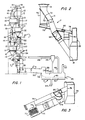
- a cement manufacturing facility which includes a preheater generally indicated at l, a calcining furnace means generally indicated at 2, a clinkering furnace generally indicated at 3 and a cooler generally indicated at 4.
- a preheater generally indicated at l
- a calcining furnace means generally indicated at 2
- a clinkering furnace generally indicated at 3
- a cooler generally indicated at 4.
- the preheater includes a plurality of serially connected gas-solids separators of the cyclone type each indicated at l0.
- Each of these cyclones l0 has an inlet ll for gas and entrained material, an outlet l2 for separated gas and an outlet l3 for separated solids.
- the system includes an inlet l5 for raw material to be treated.
- a gas conduit l6 flow connects the gas outlet l2 of each cyclone with the gas inlet ll of the next higher cyclone.
- a material duct l7 connects the material outlet l3 of each cyclone l0 with the conduit l6 of the next lower cyclone.
- Material supplied from the conduit l7 to the conduit l6 is enstrained in hot gas being discharged from the lower cyclone l0 and supplied to the upper cyclone l0 where the gas and solids are separated so that heat from the hot gas is transferred to the material as the material flows downwardly generally countercurrent to the upward gas flow through the preheater in a manner well known in the art.
- stage I being illustrated as the uppermost cyclone l0 and stage V being the lowermost cyclone with intermediate stages II, III and IV.
- Spent preheating gas in discharged from the preheater l through outlet l9 to a high efficiency dust collector (not shown).
- the calcining furnace means 2 includes a stationary calcining furnace 20 and the gas solids separator l0 which forms state V of the preheater.
- a duct 2l connects the outlet 22 of furnace 20 with the stage V cyclone l0.
- the furnace 20 also includes burner means 24 so that combustion takes place in the calcining furnace means 2.
- Preheated material to be processed is supplied by the material duct l7 from the stage IV cyclone to the material inlet 25 of the calcining furnace means 2 and vessel 20 where it is exposed to the combustion in the furnace 20 for calcining or roasting the material.
- Spent combustion gas and entrained at least partially calcined material is discharged from the furnace 20 and supplied through the outlet 22 and duct 2l to the stage V cyclone l0.
- the outlet l3 for at least partially calcined material of the stage V cyclone serves as the material outlet of the calcining furnace means 2.
- the gas outlet l2 of the stage V cyclone l0 serves as the gas outlet of the calcining means 2 for supplying preheated gas to the preheater l.
- the apparatus also includes a clinkering furnace such as a rotary kiln 30 having an inlet 3l for calcined material to be clinkered and an outlet 32 for clinkered material.
- a clinkering furnace such as a rotary kiln 30 having an inlet 3l for calcined material to be clinkered and an outlet 32 for clinkered material.
- the rotary kiln 30 includes a burner means 33 for burning fuel in the clinkering furnace 3 to complete the clinkering process.
- the system also includes a clinker cooler generally indicated at 4 which is preferably of the reciprocating grate type generally known in the art.
- This type of cooler includes a gas permeable grate 4l dividing the cooler into a lower plenum chamber 42 and an upper material chamber 43 and serves as a means for moving the clinker from the inlet 32 to the outlet 45. Cooling air is supplied from a source such as a fan 44 to the undergrate compartment 42 for passage through the reciprocating grates 4l and bed of material supported thereon to a simultaneously cool the material and heat the air.
- the cooler 4 also includes a vent duct 47 which supplies excess cooling air to a high efficiency dust collector (not shown).
- the clinkering furnace 3 includes a riser duct 35 flow connecting the clinkering furnace to the calcining furnace 2 so that exhaust gas from the kiln is supplied to the calcining furnace 2 and then the preheater l.
- the recirculation system 7 includes a duct 70 which is connected to the outlet l3 of the stage V cyclone l0 of the calcining means 2.
- the duct 70 also includes a branch 7l with a particle size classifying means 72 positioned between the duct 70 and the duct 7l.
- This particle size classifying means is preferably in the form of grizzly bars 73 (Figs. 2 and 3).
- the grizzly bars remove oversize material which can not pass between the bars so that this oversize material may be discharged from the calcining furnace through duct 7l. In a practical application, this oversize material and duct 7l are connected directly to the material inlet 3l of the clinkering furnace 3.
- the duct 70 is connected at its lower end to a conveyor 75 which may be in the form of a fluidizing gravity conveyor of the type wherein gaseous fluid from a source (not shown) if blown up through a gas permeable bottom to aerate and fluidize material in the conduit so that it flows freely down a conduit having a slight slope.
- a conveyor 75 which may be in the form of a fluidizing gravity conveyor of the type wherein gaseous fluid from a source (not shown) if blown up through a gas permeable bottom to aerate and fluidize material in the conduit so that it flows freely down a conduit having a slight slope.
- the conveyor 75 has an outlet end 76 which is flow connected to the riser duct 35 connecting the outlet 3l of the clinkering kiln 3 and the calcining furnace 2.
- the conveyor 75 has connected thereto another conduit 78 which supplies material from conduit 75 to the lower end of conduit 7l and the inlet 3l of the clinkering furnace 3. Material which is supplied through the conveyor 75 to riser duct 35 is entrained in the hot kiln exhaust gases and recirculated to the calcining furnace 20 for further roasting or calcining.
- the conduit 75 includes an adjustable gate 80 to control the fraction of material which is supplied through conduit 75 to outlet 76 and riser duct 35 (the recirculated material) and the fraction of material which is supplied through duct 78 to the duct 7l and inlet 3l of the clinkering furnace 3 (the discharge material).
- gate 80 By adjusting the position of gate 80, the quantity of material directed to the duct 78 and therefore the quantity of material supplied to riser duct 35 can be controlled.
- this quantity of material being recirculated through the calciner 2 may be as much as four times the quantity of new feed through inlet 25.
- the duct 7l, and conduit 75 may be referred to as means defining a second conduit flow connecting the material outlet l3 of the calcining furnace 2 with the riser duct 35 and thus the recirculation duct. Material which is supplied through this second conduit is entrained in the hot exhaust gases from the kiln and is recirculated to the calcining furnace 2. The hot exhaust gases from the kiln assist in calcining the material and raising the temperature inside the calciner 20.
- the conduit 70, 75, 78 and 7l define a first conduit for supplying calcined material from the material outlet l3 of the calcining furnace 2 to the material inlet 3l of the clinkering furnace 3. In the case of a simple calcining system which does not include a clinkering furnace material may be discharged from the system through duct 7l.
- a gas lock 90 is positioned in the conduit 75.
- This gas lock may be a one-way flap valve for permitting solid material to flow from the conduit 70 to the outlet 76 while preventing gas from flowing from 76 towards outlet l3.
- a gas lock 92 is included in conduit 7l for preventing exhaust gas from flowing from inlet 3l through conduit 7l to the outlet l3.
- the ducting arrangement of the present invention has the advantage that if there are large chunks of material being discharged from calcining furnace means through outlet l3 such as pieced of refractory tramp iron or agglomerations of calcined material, these large chunks will not pass through the grizzly 72 to the conduit 75, but instead will flow down enlarged conduit 7l to the inlet 3l of the clinkering furnace. This prevents such large pieces of material from blocking the conveying duct 75.
- the arrangement of the present invention also has the advantage that in the event there is a plug or blockage in the recirculating duct 75, material may fill ducts 75 and 70 up to the point of the grizzly 72, and thereafter material will flow down through the oversize material duct 7l directly to the clinkering furnace 3. While such a plug would interfere with the advantageous recirculation of at least partially calcined material back to the calciner, the system could still operate producing satisfactory product until a scheduled shut-down and clean out was possible.
- the duct 7l may thus be referred to as a means for by-passing material around the recirculation means 75 and discharge ducts 7l and 78.
Landscapes
- Engineering & Computer Science (AREA)
- Mechanical Engineering (AREA)
- General Engineering & Computer Science (AREA)
- Furnace Details (AREA)
- Crucibles And Fluidized-Bed Furnaces (AREA)
- Glass Melting And Manufacturing (AREA)
- Manufacture And Refinement Of Metals (AREA)
- Glanulating (AREA)
- Feeding, Discharge, Calcimining, Fusing, And Gas-Generation Devices (AREA)
- Curing Cements, Concrete, And Artificial Stone (AREA)
- Waste-Gas Treatment And Other Accessory Devices For Furnaces (AREA)
Applications Claiming Priority (2)
| Application Number | Priority Date | Filing Date | Title |
|---|---|---|---|
| US883420 | 1986-07-08 | ||
| US06/883,420 US4708644A (en) | 1986-07-08 | 1986-07-08 | Apparatus for roasting fine grained material |
Publications (4)
| Publication Number | Publication Date |
|---|---|
| EP0258977A2 true EP0258977A2 (de) | 1988-03-09 |
| EP0258977A3 EP0258977A3 (en) | 1990-02-07 |
| EP0258977B1 EP0258977B1 (de) | 1993-03-17 |
| EP0258977B2 EP0258977B2 (de) | 1999-10-13 |
Family
ID=25382544
Family Applications (1)
| Application Number | Title | Priority Date | Filing Date |
|---|---|---|---|
| EP87305943A Expired - Lifetime EP0258977B2 (de) | 1986-07-08 | 1987-07-06 | Vorrichtung zum Rösten von feinkörnigen Stoffen |
Country Status (10)
| Country | Link |
|---|---|
| US (1) | US4708644A (de) |
| EP (1) | EP0258977B2 (de) |
| JP (1) | JPS6325250A (de) |
| CN (1) | CN1015283B (de) |
| AU (1) | AU607423B2 (de) |
| CA (1) | CA1329479C (de) |
| DE (2) | DE3784814T3 (de) |
| ES (1) | ES2001743A4 (de) |
| MX (1) | MX165602B (de) |
| ZA (1) | ZA874065B (de) |
Families Citing this family (12)
| Publication number | Priority date | Publication date | Assignee | Title |
|---|---|---|---|---|
| DE3800895A1 (de) * | 1988-01-14 | 1989-07-27 | Krupp Polysius Ag | Verfahren und anlage zur waermebehandlung von feinkoernigem gut |
| DK167004B1 (da) * | 1990-07-11 | 1993-08-16 | Smidth & Co As F L | Fremgangsmaade og anlaeg til varmebehandling af pulverformet materiale |
| US5122190A (en) * | 1990-07-13 | 1992-06-16 | Southdown, Inc. | Method for producing a hydraulic binder |
| US6488765B1 (en) | 1997-07-30 | 2002-12-03 | Cemex, Inc. | Oxygen enrichment of cement kiln system combustion |
| US6309210B1 (en) * | 1999-03-16 | 2001-10-30 | L'air Liquide, Societe Anonyme Pour L'etude Et, L'exploitation Des Procedes Georges Claude | Kiln universal oxygen enrichment |
| US6773259B1 (en) * | 2003-08-05 | 2004-08-10 | Giant Cement Holding Inc. | Continuous solid waste derived fuel feed system for calciner kilns |
| DE102005009713A1 (de) * | 2005-03-03 | 2006-09-07 | Inficon Gmbh | Lecksuchgerät mit Schnüffelsonde |
| AT502254A1 (de) * | 2005-08-11 | 2007-02-15 | Holcim Ltd | Verfahren zum vorerhitzen von zementrohmehl sowie vorrichtung zur durchführung dieses verfahrens |
| FR2934589B1 (fr) * | 2008-08-01 | 2010-08-27 | Fives Fcb | Procede de fabrication de clinker de ciment dans une installation, et installation de fabrication de clinker de ciment en tant que telle |
| DE102009018099B4 (de) * | 2009-04-20 | 2013-01-17 | Thyssenkrupp Polysius Ag | Anlage zur Wärmebehandlung von stückigem Feststoff |
| CN103105067B (zh) * | 2013-03-06 | 2015-08-26 | 刘红锁 | 粉状物料悬浮换热装置及粉状物料换热系统 |
| CN110557945A (zh) * | 2018-04-04 | 2019-12-10 | 太平洋工程株式会社 | 有机污泥的处理装置及处理方法 |
Citations (3)
| Publication number | Priority date | Publication date | Assignee | Title |
|---|---|---|---|---|
| DE2325468A1 (de) * | 1972-05-20 | 1973-11-29 | Ishikawajima Harima Heavy Ind | Vorrichtung zum sintern von zement und aehnlichen stoffen |
| US4381916A (en) * | 1981-09-11 | 1983-05-03 | Fuller Company | Method and apparatus for roasting fine grained ores |
| EP0098923A1 (de) * | 1982-06-11 | 1984-01-25 | Krupp Polysius Ag | Vorrichtung zur Wärmebehandlung von feinkörnigem Gut |
Family Cites Families (8)
| Publication number | Priority date | Publication date | Assignee | Title |
|---|---|---|---|---|
| FR2229940B3 (de) * | 1973-05-14 | 1977-03-18 | Holderbank Gestion Conseils Sa | |
| US4201546A (en) * | 1976-07-09 | 1980-05-06 | Klockner-Humboldt-Deutz Aktiengesellschaft | Method and apparatus for the thermal treatment of alkali-containing pulverized raw material to be used in the manufacture of cement |
| AT368986B (de) * | 1978-04-07 | 1982-11-25 | Lechner Bartl Eiberg Zement | Verfahren zur herstellung eines hydraulischen bindemittels |
| US4425092A (en) * | 1978-08-02 | 1984-01-10 | Klockner-Humboldt-Deutz Ag | System for burning fine-grained material, particularly for the manufacture of cement clinkers |
| US4270900A (en) * | 1980-01-07 | 1981-06-02 | Allis-Chalmers Corporation | Suspension preheater |
| IN159327B (de) * | 1982-09-02 | 1987-05-02 | Smidth & Co As F L | |
| DE3333718A1 (de) * | 1983-09-17 | 1985-04-04 | Klöckner-Humboldt-Deutz AG, 5000 Köln | Anlage zum brennen von feinkoernigem gut, insbesondere zu zementklinker |
| US4568276A (en) * | 1984-02-15 | 1986-02-04 | Kabushiki Kaisha Kobe Seiko Sho | Dust preheating system with incipient calciner |
-
1986
- 1986-07-08 US US06/883,420 patent/US4708644A/en not_active Expired - Fee Related
-
1987
- 1987-06-03 CA CA000538702A patent/CA1329479C/en not_active Expired - Fee Related
- 1987-06-05 AU AU73863/87A patent/AU607423B2/en not_active Ceased
- 1987-06-05 ZA ZA874065A patent/ZA874065B/xx unknown
- 1987-07-03 MX MX007203A patent/MX165602B/es unknown
- 1987-07-06 EP EP87305943A patent/EP0258977B2/de not_active Expired - Lifetime
- 1987-07-06 ES ES87305943T patent/ES2001743A4/es active Pending
- 1987-07-06 DE DE3784814T patent/DE3784814T3/de not_active Expired - Fee Related
- 1987-07-06 DE DE198787305943T patent/DE258977T1/de active Pending
- 1987-07-06 CN CN87104762A patent/CN1015283B/zh not_active Expired
- 1987-07-07 JP JP62167993A patent/JPS6325250A/ja active Pending
Patent Citations (3)
| Publication number | Priority date | Publication date | Assignee | Title |
|---|---|---|---|---|
| DE2325468A1 (de) * | 1972-05-20 | 1973-11-29 | Ishikawajima Harima Heavy Ind | Vorrichtung zum sintern von zement und aehnlichen stoffen |
| US4381916A (en) * | 1981-09-11 | 1983-05-03 | Fuller Company | Method and apparatus for roasting fine grained ores |
| EP0098923A1 (de) * | 1982-06-11 | 1984-01-25 | Krupp Polysius Ag | Vorrichtung zur Wärmebehandlung von feinkörnigem Gut |
Also Published As
| Publication number | Publication date |
|---|---|
| CN1015283B (zh) | 1992-01-01 |
| CN87104762A (zh) | 1988-04-13 |
| EP0258977B1 (de) | 1993-03-17 |
| MX165602B (es) | 1992-11-25 |
| ES2001743A4 (es) | 1988-06-16 |
| AU7386387A (en) | 1988-01-14 |
| JPS6325250A (ja) | 1988-02-02 |
| DE3784814D1 (de) | 1993-04-22 |
| US4708644A (en) | 1987-11-24 |
| DE3784814T2 (de) | 1993-09-30 |
| EP0258977B2 (de) | 1999-10-13 |
| DE3784814T3 (de) | 2000-05-25 |
| DE258977T1 (de) | 1988-09-01 |
| EP0258977A3 (en) | 1990-02-07 |
| AU607423B2 (en) | 1991-03-07 |
| ZA874065B (en) | 1987-12-04 |
| CA1329479C (en) | 1994-05-17 |
Similar Documents
| Publication | Publication Date | Title |
|---|---|---|
| US4381916A (en) | Method and apparatus for roasting fine grained ores | |
| CA1058864A (en) | Apparatus for calcining raw material | |
| EP0258977B1 (de) | Vorrichtung zum Rösten von feinkörnigen Stoffen | |
| HU224118B1 (hu) | Eljárás és berendezés cementklinker előállítására | |
| EP0153048A2 (de) | Vorwärmsystem mit Vorkalzinierung für puderförmige Stoffe | |
| US4169701A (en) | Fluidized-bed kiln with preheating means | |
| US4310298A (en) | Method and device for producing coal dust | |
| CS199570B2 (en) | Apparatus for calcinating and sintering cement-making raw materials | |
| GB2127946A (en) | A method of and a plant for burning or roasting fine-grained material | |
| US2757921A (en) | Method for burning of materials with heat recovery | |
| KR930011376B1 (ko) | 분말입자 재료의 예열장치 | |
| Missalla et al. | Significant improvement of energy efficiency at alunorte’s calcination facility | |
| US4204835A (en) | Apparatus for treating solid particulate material | |
| CA1062460A (en) | Apparatus for calcining raw material | |
| JPH0424630B2 (de) | ||
| SU1759915A1 (ru) | Способ подготовки и подачи материала металлургической шихты | |
| JPH0212141B2 (de) | ||
| CA1062461A (en) | Apparatus for calcining raw material | |
| SU968564A1 (ru) | Установка дл обжига полидисперсного материала | |
| JPH08119694A (ja) | セメント原料焼成装置 | |
| JPH0327261B2 (de) | ||
| JPS6096553A (ja) | セメント原料粉末の焼成方法 | |
| CS226752B1 (cs) | Zařízení na výpal práškovitého materiálu | |
| JPS6026580B2 (ja) | 流動層式焼成装置 | |
| JPS6259390A (ja) | 複数系統型粉末原料予熱装置 |
Legal Events
| Date | Code | Title | Description |
|---|---|---|---|
| PUAI | Public reference made under article 153(3) epc to a published international application that has entered the european phase |
Free format text: ORIGINAL CODE: 0009012 |
|
| AK | Designated contracting states |
Kind code of ref document: A2 Designated state(s): DE ES FR GB IT |
|
| ITCL | It: translation for ep claims filed |
Representative=s name: STUDIO TORTA SOCIETA' SEMPLICE |
|
| EL | Fr: translation of claims filed | ||
| DET | De: translation of patent claims | ||
| PUAL | Search report despatched |
Free format text: ORIGINAL CODE: 0009013 |
|
| AK | Designated contracting states |
Kind code of ref document: A3 Designated state(s): DE ES FR GB IT |
|
| 17P | Request for examination filed |
Effective date: 19900604 |
|
| 17Q | First examination report despatched |
Effective date: 19910725 |
|
| GRAA | (expected) grant |
Free format text: ORIGINAL CODE: 0009210 |
|
| AK | Designated contracting states |
Kind code of ref document: B1 Designated state(s): DE ES FR GB IT |
|
| PG25 | Lapsed in a contracting state [announced via postgrant information from national office to epo] |
Ref country code: IT Free format text: LAPSE BECAUSE OF FAILURE TO SUBMIT A TRANSLATION OF THE DESCRIPTION OR TO PAY THE FEE WITHIN THE PRE;WARNING: LAPSES OF ITALIAN PATENTS WITH EFFECTIVE DATE BEFORE 2007 MAY HAVE OCCURRED AT ANY TIME BEFORE 2007. THE CORRECT EFFECTIVE DATE MAY BE DIFFERENT FROM THE ONE RECORDED.SCRIBED TIME-LIMIT Effective date: 19930317 Ref country code: FR Effective date: 19930317 |
|
| REF | Corresponds to: |
Ref document number: 3784814 Country of ref document: DE Date of ref document: 19930422 |
|
| PG25 | Lapsed in a contracting state [announced via postgrant information from national office to epo] |
Ref country code: GB Effective date: 19930706 |
|
| EN | Fr: translation not filed | ||
| PLBI | Opposition filed |
Free format text: ORIGINAL CODE: 0009260 |
|
| 26 | Opposition filed |
Opponent name: KRUPP POLYSIUS AG Effective date: 19931214 |
|
| GBPC | Gb: european patent ceased through non-payment of renewal fee |
Effective date: 19930706 |
|
| APAA | Appeal reference recorded |
Free format text: ORIGINAL CODE: EPIDOS REFN |
|
| APAC | Appeal dossier modified |
Free format text: ORIGINAL CODE: EPIDOS NOAPO |
|
| APAC | Appeal dossier modified |
Free format text: ORIGINAL CODE: EPIDOS NOAPO |
|
| APAC | Appeal dossier modified |
Free format text: ORIGINAL CODE: EPIDOS NOAPO |
|
| PLAW | Interlocutory decision in opposition |
Free format text: ORIGINAL CODE: EPIDOS IDOP |
|
| PLAW | Interlocutory decision in opposition |
Free format text: ORIGINAL CODE: EPIDOS IDOP |
|
| PGFP | Annual fee paid to national office [announced via postgrant information from national office to epo] |
Ref country code: DE Payment date: 19990623 Year of fee payment: 13 |
|
| PUAH | Patent maintained in amended form |
Free format text: ORIGINAL CODE: 0009272 |
|
| STAA | Information on the status of an ep patent application or granted ep patent |
Free format text: STATUS: PATENT MAINTAINED AS AMENDED |
|
| 27A | Patent maintained in amended form |
Effective date: 19991013 |
|
| AK | Designated contracting states |
Kind code of ref document: B2 Designated state(s): DE ES FR GB IT |
|
| PG25 | Lapsed in a contracting state [announced via postgrant information from national office to epo] |
Ref country code: ES Free format text: LAPSE BECAUSE OF FAILURE TO SUBMIT A TRANSLATION OF THE DESCRIPTION OR TO PAY THE FEE WITHIN THE PRESCRIBED TIME-LIMIT Effective date: 20000124 |
|
| EN | Fr: translation not filed | ||
| PG25 | Lapsed in a contracting state [announced via postgrant information from national office to epo] |
Ref country code: DE Free format text: LAPSE BECAUSE OF NON-PAYMENT OF DUE FEES Effective date: 20010501 |
|
| APAH | Appeal reference modified |
Free format text: ORIGINAL CODE: EPIDOSCREFNO |
|
| PG25 | Lapsed in a contracting state [announced via postgrant information from national office to epo] |
Ref country code: ES Free format text: LAPSE BECAUSE OF FAILURE TO SUBMIT A TRANSLATION OF THE DESCRIPTION OR TO PAY THE FEE WITHIN THE PRESCRIBED TIME-LIMIT Effective date: 19930731 |