EP0258909A2 - Anzeigegerät mit zeichenproportionalen Abständen - Google Patents
Anzeigegerät mit zeichenproportionalen Abständen Download PDFInfo
- Publication number
- EP0258909A2 EP0258909A2 EP87112997A EP87112997A EP0258909A2 EP 0258909 A2 EP0258909 A2 EP 0258909A2 EP 87112997 A EP87112997 A EP 87112997A EP 87112997 A EP87112997 A EP 87112997A EP 0258909 A2 EP0258909 A2 EP 0258909A2
- Authority
- EP
- European Patent Office
- Prior art keywords
- character
- data
- display
- display apparatus
- counter
- Prior art date
- Legal status (The legal status is an assumption and is not a legal conclusion. Google has not performed a legal analysis and makes no representation as to the accuracy of the status listed.)
- Withdrawn
Links
- 239000011295 pitch Substances 0.000 claims description 11
- 230000004044 response Effects 0.000 claims description 5
- 230000000694 effects Effects 0.000 claims description 3
- 238000012545 processing Methods 0.000 claims description 2
- 230000000875 corresponding effect Effects 0.000 description 13
- RRLHMJHRFMHVNM-BQVXCWBNSA-N [(2s,3r,6r)-6-[5-[5-hydroxy-3-(4-hydroxyphenyl)-4-oxochromen-7-yl]oxypentoxy]-2-methyl-3,6-dihydro-2h-pyran-3-yl] acetate Chemical compound C1=C[C@@H](OC(C)=O)[C@H](C)O[C@H]1OCCCCCOC1=CC(O)=C2C(=O)C(C=3C=CC(O)=CC=3)=COC2=C1 RRLHMJHRFMHVNM-BQVXCWBNSA-N 0.000 description 9
- 239000000872 buffer Substances 0.000 description 3
- 238000010586 diagram Methods 0.000 description 2
- 230000006870 function Effects 0.000 description 2
- 238000012986 modification Methods 0.000 description 2
- 230000004048 modification Effects 0.000 description 2
- 230000005540 biological transmission Effects 0.000 description 1
- 230000004397 blinking Effects 0.000 description 1
- 238000006243 chemical reaction Methods 0.000 description 1
- 238000010276 construction Methods 0.000 description 1
- 230000001276 controlling effect Effects 0.000 description 1
- 238000000034 method Methods 0.000 description 1
- 238000011144 upstream manufacturing Methods 0.000 description 1
Images


Classifications
-
- G—PHYSICS
- G09—EDUCATION; CRYPTOGRAPHY; DISPLAY; ADVERTISING; SEALS
- G09G—ARRANGEMENTS OR CIRCUITS FOR CONTROL OF INDICATING DEVICES USING STATIC MEANS TO PRESENT VARIABLE INFORMATION
- G09G5/00—Control arrangements or circuits for visual indicators common to cathode-ray tube indicators and other visual indicators
- G09G5/22—Control arrangements or circuits for visual indicators common to cathode-ray tube indicators and other visual indicators characterised by the display of characters or indicia using display control signals derived from coded signals representing the characters or indicia, e.g. with a character-code memory
- G09G5/24—Generation of individual character patterns
- G09G5/243—Circuits for displaying proportional spaced characters or for kerning
Definitions
- the present invention relates to a proportional spacing display apparatus for displaying characters with pitches correspondent with types of character on the screen of a display device such as a CRT.
- the image display generally shows characters with a fixed pitch whereas the typewriter, when the proportional spacing mode is selected, is capable of printing the characters with corresponding widths, which is pleasing to the eye.
- printed lines include various numbers of characters depending on the types of character. These lines, when shown on the display which provides a constant pitch display, are unjustified at the righthand end which presents a poor appearance. It will be convenient to the operator in preparing a document if the display presents charac ters in the form in which the characters are printed. However, the above word processor is awkward to use since the lines are justified on the typewriter but not on the display.
- proportional spacing display system For such a word processor, what is known as proportional spacing display system is being developed which enables characters to presented on the display as well with widths correspondent with the types of character.
- this system varies the frequency of a dot clock with the types of character, which requires a very complicated and expensive circuitry.
- a primary object of the present invention is to provide an improved proportional spacing display apparatus which is capable of presenting characters on a display screen with widths correspondent with the types of character.
- Another object of the present invention is to provide a proportional spacing display apparatus capable of displaying characters with widths correspondent with the types of character without varying the dot clock frequency.
- a further object of the invention is to provide a low cost proportional spacing display apparatus having a simple circuit construction.
- a proportional spacing display apparatus comprises data memory means storing character data; character data reading means for reading selected character data from the data memory means for display; data rewriting means for rewriting the character data stored in the data memory means; control means for allocating a fixed character data reading period and varying a character data rewriting period in accordance with widths of characters; and display means for displaying a character on the display device during one character display cycle corresponding to a sum of the character data reading period and the character data rewriting period determined by the control means.
- the data memory means comprises a video memory including a character memory storing character codes and an attribute memory storing attributes other than the characters.
- the character memory is connected to a character data generator for generating a bit pattern corresponding to a character code read out of the character memory, the character data generator being provided with a bit eliminator for displaying characters with varied pitches from one character bit pattern, and an output selector.
- the character memory is connected to a decoder for outputting a character width code corresponding to a character code read out of the character memory.
- the character data reading means comprises a controller for providing a display screen with synchronizing signals and an address counter for providing the data memory means with an address signal.
- the controller receives clock pulses having a fixed cycle and the address counter receives a character clock having pulsewidths variable with character widths, thereby to effect address renewals.
- the data rewriting means comprises a central processing unit.
- the control means may include a clock pulse generator, a first counter for counting the clock pulses equivalent of the number of clock pulses corresponding to a character width, a second counter for counting a predetermined number of clock pulses in response to a set strobe generated upon completion of count by the first counter, and a flip-flop settable by the set strobe generated by the first counter and resettable by a reset strobe generated upon completion of count by the second counter.
- the number of clock pulses counted by the second counter is set to a number corresponding to a minimum time period required for the reading means to make access to the data memory means for reading the character data from the data memory means.
- the flip-flop generates a character clock which comprises a first half cycle having a variable time period determined by the first counter and a second half cycle having a fixed time period determined by the second counter.
- the character clock is fed to a multiplexer for selectively providing an address signal generated by the data reading means and an address signal generated by the data rewriting means for the data memory means, to control a switching timing of the multiplexer.
- the data rewriting is effected during the first half cycle having the variable time period determined the first counter only when the time period is sufficiently long for making access and there is an access request from the data rewriting means.
- the character data may be rewritten in and read from the data memory means by a switching effected by a multiplexer between address designation signals provided by the data rewriting means and the data reading means.
- one character display cycle determines the width of the character to be displayed.
- the proportional spacing display is effected by adjusting this display cycle with the first half cycle (CPU cycle) allocated for data rewriting.
- the CPU cycle has only a short period which is inadequate for allowing the CPU to make access to the video memory, but the CPU can make access to the vide memory during a subsequent display cycle for a wide character. If an access time for the CPU is not secured during subsequent cycles, the access may be made during a horizontal blanking period after horizontal scanning of the display.
- the proportional spacing display may be provided on the display screen as well wherein characters are displayed with widths correspondent with the types of character.
- the invention is applicable to a word processor having a document editing function and including a typewriter and a display, whereby the display shows lines of characters in the same form as they are printed. This renders the word processor very convenient to use.
- the invention permits a relatively slow and inexpensive memory to be employed as the video memory.
- the proportional spacing display is effected by using a character clock having pulsewidths variable with the types of character, the pulsewidth variations being adjusted during the CPU cycle in each display cycle, with the remaining half cycle (display sequencer cycle) being fixed to a time period necessary for access to the video memory.
- the invention employs the above method, i.e. the cycle steal system.
- This system enables the CPU to carry out data reading and writing in parallel with the character display during a display cycle for a wide character, which leads to an efficient use of the CPU.
- Fig. 1 is a diagram showing a circuitry according to the present invention.
- This circuitry comprises a display sequencer 1 and a display 2 such as a CRT.
- the display sequencer includes a CRT controller 3 for generating necessary signals such as horizontal and vertical synchronizing signals H-SYNC and V-SYNC for transmission to the display 2, a video enable signal EN VIDEO and a cursor signal CURSOR, and an address counter 4 for proportional spacing display.
- This display sequencer comprises an HD68451 manufactured by Hitachi, for example.
- the circuitry further comprises a video RAM 5 including an attribute RAM 6 and a character RAM 7.
- the attribute RAM 6 stores character attributes such as brightness, whether characters are blinking or not and whether the characters are reversed or not.
- the character RAM 7 stores types of character.
- Address designation for the video RAM 5 is effected either by an address signal from the display sequencer or an address signal from a CPU, which is selected by a multiplexer 8.
- the selection by the multiplexer 8 of one of these address signals is controlled by a character clock applied to the multiplexer 8.
- the multiplexer 8 selects the address signal from the display sequencer, character data stored at addresses in the video RAM 5 designated by this address signal are read out.
- the address signal from the CPU is selected, data at addresses designated by this address signal are rewritten.
- Attribute data output from the attribute RAM 6 when the address signal from the display sequencer is selected are subjected to timing adjustment at a latch 9 and are thereafter input to attribute timing gates 10 for application of the attributes to a video signal.
- Character code data output from the character RAM 7 are subjected to timing adjustment at a latch 11 and are thereafter input to a character generator 12 and a proportional spacing decode memory 13 (which comprises a ROM in this embodiment).
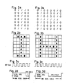
- the character generator 12 outputs a character bit pattern corresponding to a character code.
- the character code is a data for displaying "I” for example
- the character bit pattern is in the form shown in Fig. 2(a).
- the character code is for displaying "H"
- the pattern is in the form shown in Fig. 3(a).
- the bit pattern is subjected to parallel to serial conversion at a shift register 14 and is then input to the attribute timing gates 10 as the video signal.
- the illustrated example of circuitry includes a bit eliminator 15 disposed upstream of the shift register 14 for producing characters with varied pitches from the same character bit pattern, and an output selector 16 downstream of the shift register 14. These additional circuits 15 and 16, however, are not necessary if the character generator 12 is provided with bit patterns corresponding to the varied pitches.
- the proportional spacing decode memory 13 outputs a character width code corresponding to the character code.
- the memory 13 When the character code is for "I” for example, the memory 13 outputs a character width code equivalent of dot clock number 5.
- the memory 13 When the character code is for "H”, the memory 13 outputs a character width code equivalent of dot clock number 8.
- the character width data output from this proportional spacing decode ROM are input to a character clock generating circuit 17.
- the character clock generating circuit 17 comprises a clock generator 18 for generating a 24.8 MHz dot clock for example, a CPU cycle counter 19 for counting dot clock pulses corresponding to the number of clock pulses in the character width data output from the proportional spacing decode memory 13, a display sequencer cycle counter 20 for counting a predetermined number of dot clock pulses in response to a set strobe generated when the CPU cycle counter 19 is incremented, and an SR flip-flop 21 set by the set strobe generated when the CPU cycle counter 19 is incremented and reset by a reset strobe generated when the display sequencer cycle counter 20 is incremented.
- a clock generator 18 for generating a 24.8 MHz dot clock for example
- a CPU cycle counter 19 for counting dot clock pulses corresponding to the number of clock pulses in the character width data output from the proportional spacing decode memory 13
- a display sequencer cycle counter 20 for counting a predetermined number of dot clock pulses in response to a set strobe generated when the CPU cycle counter
- the predetermined number of dot clock pulses counted by the display sequencer cycle counter 20 is fixed to a number corresponding to a minimum time period required for making access to the video RAM 5.
- the number of dot clock pulses counted by the CPU cycle counter 19 is variable with the character width data.
- the SR flip-flop 21 generates a character clock which, as shown in Fig. 4, comprises a display sequencer cycle (a) having a fixed time period determined by the display sequencer cycle counter 20 and a CPU cycle (b) having a variable time period determined by the CPU cycle counter 19, the two cycles (a) and (b) constituting one character display cycle.
- the character clock thus produced is fed to the address counter 4, an arbiter 22 and the latches 9 and 11.
- the CRT controller 3 in the display sequencer 1 receives a fixed frequency clock signal which is produced by dividing the dot clock at a 1/6 divider 23 for example. This is necessary for uniformalizing leading addresses for lines of characters on the display, and for outputting the horizontal synchronizing signal H-SYNC and the vertical synchronizing signal V-SYNC always with a fixed timing.
- the address counter 4 is loaded with an address output by the CRT controller 3 at the leading end of each display line in synchronism with the horizontal synchronizing signal. After the leading address is loaded, the address counter 4 increments or decrements the count in accordance with the character clock. Since the character clock has pulsewidths variable with character widths, the address counter 4 is renewed in accordance with a character display width, thereby causing one display cycle and the address renewal to coincide with each other for orderly display.
- the arbiter 22 is a circuit for controlling the video RAM 5 in accordance with the CPU cycle and display sequencer cycle in combination.
- the arbiter 22 provides the video RAM 5 with the strobe signal of the display sequencer during the display sequencer cycle, and renders effective or operative the strobe signal from the CPU and a CPU buss buffer 24 during the CPU cycle only when its cycle period is sufficiently long for making access and there is an access request from the CPU.
- the presence or absence of the access request from the CPU is judged from a fall in the character clock (Fig. 4).
- a next CPU cycle is appointed for the access. If the character width for the next CPU cycle is smaller than a predetermined width, then the access of the CPU must wait till a cycle to follow. If this situation continues, the access of the CPU will be kept waiting for a long time. However, there will occur no inconvenience since the display sequencer cycle is not required during a horizontal blanking time which will certainly make the access possible.
- the video RAM 5 has the following relationship with a display screen in order to provide the proportional spacing presentation on the display 2.
- the number of printable characters is calculated where minimum pitch characters in character fonts are used with respect to the width of a sheet of paper for use on the typewriter.
- the number is set for one line and input to a register of display character number in the CRT controller 3. This number is a maximum number of characters for one line printing.
- the display sequencer 1 outputs the heat address of each line which is determined by adding the number of characters in one line to the head address of the preceding line. This provides a correct address designation for the video RAM 5.
- Fig. 1 shows a latch, and numbers 26 and 27 indicate buffers. Through these buffers 26 and 27 the display 2 receives the horizontal and vertical synchronizing signals and the video signal produced by the video RAM 5, character generator 12, shift register 14 and other circuits. Thus, a selected character is displayed with a selected width at a position on the screen corresponding to a raster address designated by the CRT controller 3.
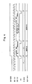
- Fig. 5 shows a proportional spacing display effected by the described proportional spacing display apparatus, and displays with fixed pitches. In Fig. 5, reference l represents a document displayed with the proportional spacing and reference m represents documents displayed with fixed pitches.
Landscapes
- Engineering & Computer Science (AREA)
- Physics & Mathematics (AREA)
- Computer Hardware Design (AREA)
- General Physics & Mathematics (AREA)
- Theoretical Computer Science (AREA)
- Controls And Circuits For Display Device (AREA)
- Digital Computer Display Output (AREA)
Applications Claiming Priority (2)
| Application Number | Priority Date | Filing Date | Title |
|---|---|---|---|
| JP61208758A JPS6363088A (ja) | 1986-09-04 | 1986-09-04 | プロポ−シヨナルスペ−シング表示方法及び装置 |
| JP208758/86 | 1986-09-04 |
Publications (2)
| Publication Number | Publication Date |
|---|---|
| EP0258909A2 true EP0258909A2 (de) | 1988-03-09 |
| EP0258909A3 EP0258909A3 (de) | 1990-11-22 |
Family
ID=16561594
Family Applications (1)
| Application Number | Title | Priority Date | Filing Date |
|---|---|---|---|
| EP19870112997 Withdrawn EP0258909A3 (de) | 1986-09-04 | 1987-09-04 | Anzeigegerät mit zeichenproportionalen Abständen |
Country Status (3)
| Country | Link |
|---|---|
| US (1) | US4864518A (de) |
| EP (1) | EP0258909A3 (de) |
| JP (1) | JPS6363088A (de) |
Families Citing this family (11)
| Publication number | Priority date | Publication date | Assignee | Title |
|---|---|---|---|---|
| AUPQ131399A0 (en) * | 1999-06-30 | 1999-07-22 | Silverbrook Research Pty Ltd | A method and apparatus (NPAGE02) |
| JP2854300B2 (ja) * | 1987-05-22 | 1999-02-03 | キヤノン株式会社 | 文字処理装置 |
| US5021974A (en) * | 1988-09-13 | 1991-06-04 | Microsoft Corporation | Method for updating a display bitmap with a character string or the like |
| JPH075996Y2 (ja) * | 1990-03-02 | 1995-02-15 | 川崎重工業株式会社 | 工業用ロボットの手首部シール装置 |
| GB2259835B (en) * | 1991-09-18 | 1995-05-17 | Rohm Co Ltd | Character generator and video display device using the same |
| JPH05210085A (ja) * | 1992-01-30 | 1993-08-20 | Canon Inc | 表示制御装置 |
| US5633656A (en) * | 1993-05-05 | 1997-05-27 | Acer Peripherals, Inc. | Controlling apparatus for display of an on-screen menu in a display device |
| US5721568A (en) * | 1995-06-28 | 1998-02-24 | Lg Semicon Co., Ltd. | Font ROM control circuit for on-screen display |
| US5724067A (en) * | 1995-08-08 | 1998-03-03 | Gilbarco, Inc. | System for processing individual pixels to produce proportionately spaced characters and method of operation |
| KR100234395B1 (ko) * | 1996-11-13 | 1999-12-15 | 윤종용 | 다양한 온 스크린 디스플레이 기능들을 수행하는장치 및 방법 |
| AU2002952483A0 (en) * | 2002-11-05 | 2002-11-21 | Silverbrook Research Pty Ltd | Methods and Systems (NPW009) |
Family Cites Families (9)
| Publication number | Priority date | Publication date | Assignee | Title |
|---|---|---|---|---|
| US3267454A (en) * | 1963-06-24 | 1966-08-16 | Ibm | Line justifying and proportional spacing apparatus for display devices |
| US3276008A (en) * | 1963-08-08 | 1966-09-27 | Dick Co Ab | Character alignment and proportional spacing system |
| US3588873A (en) * | 1968-11-12 | 1971-06-28 | Hewlett Packard Co | Information display apparatus |
| US3754229A (en) * | 1972-06-29 | 1973-08-21 | Redactron Corp | Proportional symbol display |
| US3952296A (en) * | 1973-11-23 | 1976-04-20 | Xerox Corporation | Video signal generating apparatus with separate and simultaneous processing of odd and even video bits |
| US4348738A (en) * | 1977-08-01 | 1982-09-07 | R & I Patent Corporation | Electronic typographical display device with justification feature |
| US4246578A (en) * | 1978-02-08 | 1981-01-20 | Matsushita Electric Industrial Co., Ltd. | Pattern generation display system |
| GB2048624B (en) * | 1979-05-02 | 1982-12-15 | Ibm | Graphics display apparatus |
| US4555763A (en) * | 1982-07-01 | 1985-11-26 | Decision Data Computer Corp. | Method and apparatus for storage and accessing of characters, and electronic printer employing same |
-
1986
- 1986-09-04 JP JP61208758A patent/JPS6363088A/ja active Pending
-
1987
- 1987-09-04 EP EP19870112997 patent/EP0258909A3/de not_active Withdrawn
- 1987-09-04 US US07/094,310 patent/US4864518A/en not_active Expired - Fee Related
Also Published As
| Publication number | Publication date |
|---|---|
| EP0258909A3 (de) | 1990-11-22 |
| US4864518A (en) | 1989-09-05 |
| JPS6363088A (ja) | 1988-03-19 |
Similar Documents
| Publication | Publication Date | Title |
|---|---|---|
| US4228430A (en) | CRT Display apparatus with changeable cursor indicia | |
| US4450442A (en) | Display processor for superimposed-picture display system | |
| US4864518A (en) | Proportional spacing display apparatus | |
| EP0069517B1 (de) | Zeichenanzeigeeinrichtung | |
| KR920000455B1 (ko) | 인터페이스 장치 | |
| US4555763A (en) | Method and apparatus for storage and accessing of characters, and electronic printer employing same | |
| US4149264A (en) | CRT display apparatus of raster scanning type | |
| US4562402A (en) | Method and apparatus for generating phase locked digital clock signals | |
| JP3375764B2 (ja) | 字体生成装置 | |
| US4071910A (en) | Time-multiplexed output devices in video terminal systems | |
| EP0381426A2 (de) | Vorrichtung zur Bestimmung der Position eines Lichtgriffels auf einem Anzeigegerät | |
| EP0258825A2 (de) | Vorrichtung zur Anzeigesteuerung mit verbesserter Attribut-Funktion | |
| JPS6217833Y2 (de) | ||
| EP0110180A1 (de) | Speichergerät für Videodaten | |
| US6670956B2 (en) | Apparatus and method for automatically controlling on-screen display font height | |
| US4985852A (en) | Method of and apparatus for driving a dot array recorder | |
| US5197119A (en) | External synchronism control circuit | |
| JP2871164B2 (ja) | 画像処理装置 | |
| EP0163177B1 (de) | Einrichtung zum Generieren von Bildfensterseitenlinien für eine Kathodenstrahlanzeigeeinrichtung | |
| JPH05341750A (ja) | データ処理装置用ディスプレイの表示制御装置 | |
| KR920004991Y1 (ko) | 평판 표시기용 수평 동기신호 제어회로 | |
| JPS61156431A (ja) | 表示用ビデオ信号発生装置 | |
| JPS6261156B2 (de) | ||
| SU1587484A1 (ru) | Устройство дл вывода символьной информации на экран электронно-лучевой трубки | |
| Matherat | A chip for low-cost raster-scan graphic display |
Legal Events
| Date | Code | Title | Description |
|---|---|---|---|
| PUAI | Public reference made under article 153(3) epc to a published international application that has entered the european phase |
Free format text: ORIGINAL CODE: 0009012 |
|
| AK | Designated contracting states |
Kind code of ref document: A2 Designated state(s): DE FR GB |
|
| PUAL | Search report despatched |
Free format text: ORIGINAL CODE: 0009013 |
|
| AK | Designated contracting states |
Kind code of ref document: A3 Designated state(s): DE FR GB |
|
| STAA | Information on the status of an ep patent application or granted ep patent |
Free format text: STATUS: THE APPLICATION IS DEEMED TO BE WITHDRAWN |
|
| 18D | Application deemed to be withdrawn |
Effective date: 19901001 |
|
| RIN1 | Information on inventor provided before grant (corrected) |
Inventor name: KURITA, KIKUO |