EP0258192A2 - Vorrichtung mit Mikroprozessor zur kontinuierlichen Anzeige einer Analogskala - Google Patents
Vorrichtung mit Mikroprozessor zur kontinuierlichen Anzeige einer Analogskala Download PDFInfo
- Publication number
- EP0258192A2 EP0258192A2 EP87830310A EP87830310A EP0258192A2 EP 0258192 A2 EP0258192 A2 EP 0258192A2 EP 87830310 A EP87830310 A EP 87830310A EP 87830310 A EP87830310 A EP 87830310A EP 0258192 A2 EP0258192 A2 EP 0258192A2
- Authority
- EP
- European Patent Office
- Prior art keywords
- microprocessor
- circuit device
- monitor
- scale
- analog
- Prior art date
- Legal status (The legal status is an assumption and is not a legal conclusion. Google has not performed a legal analysis and makes no representation as to the accuracy of the status listed.)
- Withdrawn
Links
- 230000003287 optical effect Effects 0.000 claims description 8
- 238000000034 method Methods 0.000 claims description 4
- 230000008569 process Effects 0.000 claims description 4
- 230000000694 effects Effects 0.000 claims description 3
- 238000005259 measurement Methods 0.000 abstract description 16
- 230000008859 change Effects 0.000 description 7
- 210000000352 storage cell Anatomy 0.000 description 4
- 230000008447 perception Effects 0.000 description 3
- 238000013459 approach Methods 0.000 description 2
- 238000010586 diagram Methods 0.000 description 2
- 238000012545 processing Methods 0.000 description 2
- 238000005303 weighing Methods 0.000 description 2
- 230000036461 convulsion Effects 0.000 description 1
- 238000011161 development Methods 0.000 description 1
- 230000006870 function Effects 0.000 description 1
- 230000004048 modification Effects 0.000 description 1
- 230000010355 oscillation Effects 0.000 description 1
- 230000002688 persistence Effects 0.000 description 1
- 239000010453 quartz Substances 0.000 description 1
- VYPSYNLAJGMNEJ-UHFFFAOYSA-N silicon dioxide Inorganic materials O=[Si]=O VYPSYNLAJGMNEJ-UHFFFAOYSA-N 0.000 description 1
Images
Classifications
-
- G—PHYSICS
- G01—MEASURING; TESTING
- G01R—MEASURING ELECTRIC VARIABLES; MEASURING MAGNETIC VARIABLES
- G01R13/00—Arrangements for displaying electric variables or waveforms
- G01R13/20—Cathode-ray oscilloscopes
- G01R13/22—Circuits therefor
- G01R13/30—Circuits for inserting reference markers, e.g. for timing, for calibrating, for frequency marking
-
- G—PHYSICS
- G01—MEASURING; TESTING
- G01G—WEIGHING
- G01G19/00—Weighing apparatus or methods adapted for special purposes not provided for in the preceding groups
- G01G19/40—Weighing apparatus or methods adapted for special purposes not provided for in the preceding groups with provisions for indicating, recording, or computing price or other quantities dependent on the weight
- G01G19/413—Weighing apparatus or methods adapted for special purposes not provided for in the preceding groups with provisions for indicating, recording, or computing price or other quantities dependent on the weight using electromechanical or electronic computing means
- G01G19/414—Weighing apparatus or methods adapted for special purposes not provided for in the preceding groups with provisions for indicating, recording, or computing price or other quantities dependent on the weight using electromechanical or electronic computing means using electronic computing means only
-
- G—PHYSICS
- G01—MEASURING; TESTING
- G01R—MEASURING ELECTRIC VARIABLES; MEASURING MAGNETIC VARIABLES
- G01R13/00—Arrangements for displaying electric variables or waveforms
- G01R13/20—Cathode-ray oscilloscopes
- G01R13/22—Circuits therefor
Definitions
- This invention relates to a microprocessor circuit device for continuously displaying a scale of the analog type, of the type which comprises a transducer for a quantity to be measured, circuit-wise connected to an analog-to-digital converter which converts an analog-type signal from the transducer into another, digital-type signal which is supplied to a microprocessor system which processes, through a video interface and its matching card, the input information to control the monitor tube whereon an optical scale of the quantity being measured is displayed.
- tapes provided with measuring notches have been used originally which have been utilized as measurement indicator means, either in a wound up condition or a stretched out condition.
- the roll has a length of its own, thereby it cannot represent an infinite number of measurements. Furthermore, when changing units of measurements, one has also to change the type of the roll or strip accordingly.
- This invention has for its purpose the removal of the above-cited drawbacks, relating to the display devices currently in use, by making and providing a device for continuously displaying a scale of the analog type which affords direct perception of a measurement being carried out without any limitation to the range and/or change of measurement units, and ranking high in instrumental reliability.
- a microprocessor circuit device for continuously displaying a scale of the analog type, of the type which comprises a transducer for the quantity to be measured, circuit-wise connected to an analog-to-digital converter which converts the analog-type signal from the transducer into another digital type signal which is supplied to a microprocessor system which processes, through a video interface and its matching card, the input information to control the monitor tube whereon an optical scale of the quantity being measured is displayed, characterized in that said video interface has a control logic which effects through a controller a fast updating of a dynamic RAM storage, wherewith it interacts, on addresses and data being supplied from the cited microprocessor system, connected circuit-wise to said logics, thereby supplying then the data read in the RAM storage to a serializer, whence data will ultimately issue to effectively control the pixels on the monitor, thus bringing about continuous displaying of the cited optical scale.
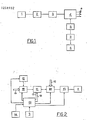
- a generic measuring instrument such as an industrial weighing balance.
- a weight transducer which sends a signal to an analog-to-digital converter 3 having the function of matching, as by converting it, the analog-type signal, e.g. a voltage, from the transducer to a microprocessor system 4 which only accepts and reads out logic levels, that is, digital signals.
- an analog-to-digital converter 3 having the function of matching, as by converting it, the analog-type signal, e.g. a voltage, from the transducer to a microprocessor system 4 which only accepts and reads out logic levels, that is, digital signals.
- That microprocessor system 4 being equipped with a suitable software allocated in in EPROM storage, processes the input information, and through a particular video interface 5 controls and manages the spots (pixels) on the cathode ray tube of the monitor 6, provided with a video matching board 7.
- the microprocessor system 4 also has further outputs 8 for optional connection to keyboards, printers, plotters, automation systems, etc. With reference to the second-mentioned drawing figure, this shows a further block specification of the video interface 5 shown in Figure 1. In fact, all the control signals from the microprocessor system 4 would reach the video interface 5 with the intermediary of an I/O interface 9.
- Such signals are then supplied to a control logic 10, which is a circuit module operationally performing control of a dynamic RAM storage 11, of a CRT controller 12 which manages the cathode ray tube of the monitor 6, as well as of a serializer formed by a shift register 13, which are all connected circuit-wise to the control logic 10 itself.
- a control logic 10 which is a circuit module operationally performing control of a dynamic RAM storage 11, of a CRT controller 12 which manages the cathode ray tube of the monitor 6, as well as of a serializer formed by a shift register 13, which are all connected circuit-wise to the control logic 10 itself.
- Data to be sent to the RAM storage 11 are supplied through a specific data bus 15, the related addresses being transmitted through a respective address bus 16.
- control logics 10 allows the storage cells of the RAM 11 to be read and written respectively through specific enables 17 and 18.
- the pixels which represent the spots on the cathode ray tube of the monitor 6, are each described by a plurality of bits identifying each position. This means that each bit configuration stored in the RAM 11 will identify, as mentioned, one pixel configuration on the monitor, i.e. the so-called video display. Because the RAMs are dynamic ones, for each update of them there corresponds a particular configuration, which may convert optically on the monitor 6 in either persistence of the same image or its development into another image.
- the change or otherwise is decided by the microprocessor system 4 according to the change or else signals supplied to it by the transducer 2 and on completion of the processing carried out by the software allocated thereto.
- it is the control logic 10 which effects, subsequently to said processing, the updating of the storage cells in the RAM 11, and hence, correspondingly of the pixels on the monitor 6 by means of the CRT controller 12.
- the RAM storage 11 updating rate is of 2 bytes per microsecond. Thus, the displaying on the monitor 6 will appear continuous and without unpleasant jerks for the observer.
- Each character displayed is, by managing the pixels on the monitor 6, encoded at 16 bits.
- the microprocessor system 4 can go to read and write anything in the RAMs 11, by using the signals 17 and 18 respectively.
- the microprocessor system 4 will send depending on the signals from the transducer 2 and basing upon its own software which equips it, commands and information to the control logic 10, which updates at a high rate the dynamic RAMs 11 and provides, through the CRT controller 12 and the shift register 13, a corresponding video display on the monitor 6 representing an optical scale, and this for each data and address configuration presently in the storage cells of those same RAMs.
Landscapes
- Physics & Mathematics (AREA)
- General Physics & Mathematics (AREA)
- Engineering & Computer Science (AREA)
- Mathematical Physics (AREA)
- Theoretical Computer Science (AREA)
- Controls And Circuits For Display Device (AREA)
- Digital Computer Display Output (AREA)
Applications Claiming Priority (2)
| Application Number | Priority Date | Filing Date | Title |
|---|---|---|---|
| IT2155986 | 1986-08-29 | ||
| IT8621559A IT1213486B (it) | 1986-08-29 | 1986-08-29 | Dispositivo circuitale a microprocessore per la visualizzazione continua di una scala di tipo analogico. |
Publications (2)
| Publication Number | Publication Date |
|---|---|
| EP0258192A2 true EP0258192A2 (de) | 1988-03-02 |
| EP0258192A3 EP0258192A3 (de) | 1990-01-24 |
Family
ID=11183597
Family Applications (1)
| Application Number | Title | Priority Date | Filing Date |
|---|---|---|---|
| EP87830310A Withdrawn EP0258192A3 (de) | 1986-08-29 | 1987-08-25 | Vorrichtung mit Mikroprozessor zur kontinuierlichen Anzeige einer Analogskala |
Country Status (2)
| Country | Link |
|---|---|
| EP (1) | EP0258192A3 (de) |
| IT (1) | IT1213486B (de) |
Cited By (1)
| Publication number | Priority date | Publication date | Assignee | Title |
|---|---|---|---|---|
| GB2398386A (en) * | 2003-02-04 | 2004-08-18 | Charder Electronic Co Ltd | Digital and analogue display |
Citations (3)
| Publication number | Priority date | Publication date | Assignee | Title |
|---|---|---|---|---|
| US4318183A (en) * | 1978-12-22 | 1982-03-02 | Raytheon Company | Multiple channel digital memory system |
| EP0074235A1 (de) * | 1981-09-08 | 1983-03-16 | Grumman Aerospace Corporation | Programmierbarer Signalanalysator |
| DE3419218A1 (de) * | 1983-06-10 | 1984-12-13 | Mettler Instrumente AG, Greifensee | Verfahren zur optischen gewichtsdarstellung bei dosiervorgaengen sowie dosierwaage zur durchfuehrung des verfahrens |
-
1986
- 1986-08-29 IT IT8621559A patent/IT1213486B/it active
-
1987
- 1987-08-25 EP EP87830310A patent/EP0258192A3/de not_active Withdrawn
Patent Citations (3)
| Publication number | Priority date | Publication date | Assignee | Title |
|---|---|---|---|---|
| US4318183A (en) * | 1978-12-22 | 1982-03-02 | Raytheon Company | Multiple channel digital memory system |
| EP0074235A1 (de) * | 1981-09-08 | 1983-03-16 | Grumman Aerospace Corporation | Programmierbarer Signalanalysator |
| DE3419218A1 (de) * | 1983-06-10 | 1984-12-13 | Mettler Instrumente AG, Greifensee | Verfahren zur optischen gewichtsdarstellung bei dosiervorgaengen sowie dosierwaage zur durchfuehrung des verfahrens |
Non-Patent Citations (1)
| Title |
|---|
| W[GEN + DOSIEREN, vol. 15, no. 2, March 1984, pages 67-69, Mainz, DE; M.KOCHSIEK: "Entwicklungstendenzen bei elektromechanischen Waagen" * |
Cited By (2)
| Publication number | Priority date | Publication date | Assignee | Title |
|---|---|---|---|---|
| GB2398386A (en) * | 2003-02-04 | 2004-08-18 | Charder Electronic Co Ltd | Digital and analogue display |
| GB2398386B (en) * | 2003-02-04 | 2005-02-09 | Charder Electronic Co Ltd | Digital type pointer indicator |
Also Published As
| Publication number | Publication date |
|---|---|
| IT1213486B (it) | 1989-12-20 |
| EP0258192A3 (de) | 1990-01-24 |
| IT8621559A0 (it) | 1986-08-29 |
Similar Documents
| Publication | Publication Date | Title |
|---|---|---|
| EP1116210B1 (de) | Flachbildschirm mit zwei cpu's für flugzeugcockpit | |
| JP2925119B2 (ja) | プログラマブル・コントローラ | |
| US5946641A (en) | Universal measuring instrument with signal processing algorithm encapsulated into interchangeable intelligent detectors | |
| EP0265134B1 (de) | Verfahren und Vorrichtung zur Konfiguration eines Messinstruments und konfigurierbares Messinstrument | |
| US4317199A (en) | Diagnostic extender test apparatus | |
| CN101587009A (zh) | 微小型光电液晶显示器动态图像传输装置 | |
| JPS63253263A (ja) | カーソル表示方法 | |
| EP0258192A2 (de) | Vorrichtung mit Mikroprozessor zur kontinuierlichen Anzeige einer Analogskala | |
| US5508721A (en) | Display unit having automatic testing function | |
| EP0123381B1 (de) | Gerät zur Wiedergabe logischer Daten | |
| DK150413B (da) | Marineradaranlaeg med antikollisionssystem | |
| US4992970A (en) | System for reading or setting printed circuit boards voltage of computer by support processor | |
| US4375635A (en) | Signal measurement apparatus | |
| EP0084374A2 (de) | Digitale Bildverarbeitungs- und Anzeigetechniken unter Verwendung von unterschiedlichen Bildintensitätsbestimmungen | |
| US5949495A (en) | Digital cursors for serial digital television waveform monitors | |
| JP2668396B2 (ja) | データ表示装置 | |
| JPH05272970A (ja) | 自動レベル | |
| US4956640A (en) | Method and apparatus for controlling video display priority | |
| JP3147203B2 (ja) | 信号波形測定器 | |
| NL7905116A (nl) | Elektronische registreerinrichting. | |
| US4737955A (en) | Switch closure test method and apparatus | |
| SU739584A1 (ru) | Устройство дл управлени маркером на экране электроннолучевой трубки | |
| JPS58180911A (ja) | 多チヤンネル量の指示方法 | |
| JPH01184416A (ja) | 計器 | |
| Coulton | A new data acquisition, display and control system for the ARA transonic wind tunnel |
Legal Events
| Date | Code | Title | Description |
|---|---|---|---|
| PUAI | Public reference made under article 153(3) epc to a published international application that has entered the european phase |
Free format text: ORIGINAL CODE: 0009012 |
|
| AK | Designated contracting states |
Kind code of ref document: A2 Designated state(s): AT BE CH DE ES FR GB GR IT LI LU NL SE |
|
| PUAL | Search report despatched |
Free format text: ORIGINAL CODE: 0009013 |
|
| RHK1 | Main classification (correction) |
Ipc: G01G 23/37 |
|
| AK | Designated contracting states |
Kind code of ref document: A3 Designated state(s): AT BE CH DE ES FR GB GR IT LI LU NL SE |
|
| STAA | Information on the status of an ep patent application or granted ep patent |
Free format text: STATUS: THE APPLICATION IS DEEMED TO BE WITHDRAWN |
|
| 18D | Application deemed to be withdrawn |
Effective date: 19900725 |
|
| RIN1 | Information on inventor provided before grant (corrected) |
Inventor name: GIBERTINI PAOLO |