EP0256750A2 - Ultraschall-Zerstäuber - Google Patents
Ultraschall-Zerstäuber Download PDFInfo
- Publication number
- EP0256750A2 EP0256750A2 EP87306892A EP87306892A EP0256750A2 EP 0256750 A2 EP0256750 A2 EP 0256750A2 EP 87306892 A EP87306892 A EP 87306892A EP 87306892 A EP87306892 A EP 87306892A EP 0256750 A2 EP0256750 A2 EP 0256750A2
- Authority
- EP
- European Patent Office
- Prior art keywords
- horn
- ultrasonic
- atomizing
- liquid material
- flared portion
- Prior art date
- Legal status (The legal status is an assumption and is not a legal conclusion. Google has not performed a legal analysis and makes no representation as to the accuracy of the status listed.)
- Granted
Links
Images


Classifications
-
- F—MECHANICAL ENGINEERING; LIGHTING; HEATING; WEAPONS; BLASTING
- F02—COMBUSTION ENGINES; HOT-GAS OR COMBUSTION-PRODUCT ENGINE PLANTS
- F02M—SUPPLYING COMBUSTION ENGINES IN GENERAL WITH COMBUSTIBLE MIXTURES OR CONSTITUENTS THEREOF
- F02M69/00—Low-pressure fuel-injection apparatus ; Apparatus with both continuous and intermittent injection; Apparatus injecting different types of fuel
- F02M69/04—Injectors peculiar thereto
- F02M69/041—Injectors peculiar thereto having vibrating means for atomizing the fuel, e.g. with sonic or ultrasonic vibrations
-
- B—PERFORMING OPERATIONS; TRANSPORTING
- B05—SPRAYING OR ATOMISING IN GENERAL; APPLYING FLUENT MATERIALS TO SURFACES, IN GENERAL
- B05B—SPRAYING APPARATUS; ATOMISING APPARATUS; NOZZLES
- B05B17/00—Apparatus for spraying or atomising liquids or other fluent materials, not covered by the preceding groups
- B05B17/04—Apparatus for spraying or atomising liquids or other fluent materials, not covered by the preceding groups operating with special methods
- B05B17/06—Apparatus for spraying or atomising liquids or other fluent materials, not covered by the preceding groups operating with special methods using ultrasonic or other kinds of vibrations
- B05B17/0607—Apparatus for spraying or atomising liquids or other fluent materials, not covered by the preceding groups operating with special methods using ultrasonic or other kinds of vibrations generated by electrical means, e.g. piezoelectric transducers
- B05B17/0623—Apparatus for spraying or atomising liquids or other fluent materials, not covered by the preceding groups operating with special methods using ultrasonic or other kinds of vibrations generated by electrical means, e.g. piezoelectric transducers coupled with a vibrating horn
-
- F—MECHANICAL ENGINEERING; LIGHTING; HEATING; WEAPONS; BLASTING
- F23—COMBUSTION APPARATUS; COMBUSTION PROCESSES
- F23D—BURNERS
- F23D11/00—Burners using a direct spraying action of liquid droplets or vaporised liquid into the combustion space
- F23D11/34—Burners using a direct spraying action of liquid droplets or vaporised liquid into the combustion space by ultrasonic means or other kinds of vibrations
- F23D11/345—Burners using a direct spraying action of liquid droplets or vaporised liquid into the combustion space by ultrasonic means or other kinds of vibrations with vibrating atomiser surfaces
-
- F—MECHANICAL ENGINEERING; LIGHTING; HEATING; WEAPONS; BLASTING
- F02—COMBUSTION ENGINES; HOT-GAS OR COMBUSTION-PRODUCT ENGINE PLANTS
- F02B—INTERNAL-COMBUSTION PISTON ENGINES; COMBUSTION ENGINES IN GENERAL
- F02B1/00—Engines characterised by fuel-air mixture compression
- F02B1/02—Engines characterised by fuel-air mixture compression with positive ignition
- F02B1/04—Engines characterised by fuel-air mixture compression with positive ignition with fuel-air mixture admission into cylinder
-
- Y—GENERAL TAGGING OF NEW TECHNOLOGICAL DEVELOPMENTS; GENERAL TAGGING OF CROSS-SECTIONAL TECHNOLOGIES SPANNING OVER SEVERAL SECTIONS OF THE IPC; TECHNICAL SUBJECTS COVERED BY FORMER USPC CROSS-REFERENCE ART COLLECTIONS [XRACs] AND DIGESTS
- Y10—TECHNICAL SUBJECTS COVERED BY FORMER USPC
- Y10T—TECHNICAL SUBJECTS COVERED BY FORMER US CLASSIFICATION
- Y10T74/00—Machine element or mechanism
- Y10T74/10—High frequency vibratory devices
Definitions
- the present invention relates generally to the art of atomizing liquid material by ultrasonic vibration, and particularly to an ultrasonic atomizing apparatus for atomizing and vaporizing fuel for internal combustion engines such as diesel engines and gasoline engines and external combustion engines such as boilers and burners and also suitably useful for drying and producing powdered medicines. While this invention is useful for atomizing liquid material in various applications as mentioned above, the invention will be mainly described hereinafter with respect to atomizing and vaporizing liquid fuel for internal combustion engines such as diesel engines and gasoline engines by ultrasonic vibrations.
- liquid material herein used is intended to mean not only a liquid such as liquid fuel but also various solutions and slurries such as liquid for producing medicines.
- the ultrasonic atomizing apparatus of the type described herein includes ultrasonic vibration generating means having an electric-acoustic transducer and a high frequency oscillator, and an ultrasonic vibrator horn powered by the ultrasonic vibration generating means for atomizing liquid material such as liquid fuel supplied.
- the spray properties of the ultrasonic vibrator horn such as the flow rate of liquid fuel spray as atomized, the particle size of the atomizer droplets, etc. have various effects on the performance of a combusting apparatus incorporating such ultrasonic atomizer.
- poor spray properties of the ultrasonic vibrator horn may bring forth various troubles such as inability to effect precise control of fuel-air ratio in the combusting apparatus, and worsened combusting conditions which may lead to an increase in the amount of hydrocarbon and carbon monoxide contained in the exhaust gases as well as an increase in the amount of soot produced.
- it is required to improve the atomizing properties of the ultrasonic vibrator horn as described above.
- a sonic energy generated by a piezoelectric sonic generator is used to oscillate the sonic probe, the vibrations of the probe being in turn utilized to atomize the fuel supplied to the probe in the atomizing area of the probe.
- the sonic probe is a solid member having a large mass, as described above, a great amount of sonic energy is required to obtain a great amplitude enough for atomizing the fuel.
- a great energy is required to atomize fuel in large quantities. Consequently, the stresses generated in the probe are large to excess, resulting in making it difficult to atomize fuel in large quantities effectively.
- a sonic energy (amplitude energy, for example) transmitted from the piezoelectric sonic generator to the atomizing section of the solid sonic probe to be utilized for atomization of fuel supplied is of substantially the same magnitude as the sonic energy (amplitude energy) initially provided by the piezoelectric sonic generator since the sonic probe is a solid mass, if no account is taken of any attenuation of the energy due to the mass. It cannot thus be said that the sonic energy is utilized effectually and effectively.
- the amount of energy required to atomize the fuel supplied in the atomizing area of the sonic probe depends upon the effective amplitude of vibration imparted to the fuel fed onto the atomizing section of the sonic probe, as that of the initial sonic energy, as stated above, it cannot be said that the energy from the sonic generator is effectually utilized so as to increase the effective amplitude.
- the term "effective amplitude" herein used means the amplitude required to atomize liquid, that is, the component of amplitude perpendicular to the plane of the atomizing surface onto which liquid is fed, as expressed by an absolute amplitude X sin ⁇ where ⁇ is an angle at which the atomizing surface is inclined to the central axis of the horn Accordingly, it is to be noted that the sonic energy from the sonic generator is not utilized effectively and effectually to atomize the fuel to fine droplets, resulting in an increase in the power consumption for atomization of the fuel, as pointed out above.
- the sonic probe is a solid element, the effect of the mass of the probe on attenuation of the sonic energy is noticeably large.
- the Cottell apparatus Furthermore, with the Cottell apparatus, a pool of liquid will grow around the outer periphery of the sleeve adjacent its lower end , so that liquid drops from such grown pool to form coarse droplets. It cannot thus be said that the apparatus is capable of completely atomizing a large quantity of fuel to a fine particle size in an effective manner.
- the present invention contemplates improving the conventional ultrasonic vibratory atomizing apparatus such as the Cottell apparatus to provide for effective atomization of liquid material in a short time and in large quantities as required, depending, for example, upon load variations on an internal combustion engine.
- an ultrasonic vibrator horn for connection, at one end to an ultrasonic vibration generating means in an ultrasonic atomizing apparatus, the horn having at its other end an end portion flared and enlarged in diameter towards the tip end of the horn, the horn, in use of said apparatus, being adapted to atomize liquid material on said flared portion as the liquid material is supplied from liquid material supply means to the flared portion, and being characterized by a hollow recess formed in said flared portion, said hollow recess opening towards the tip end of the horn, the geometry of said hollow recess being such that the hollow recessed section of the horn has an approximately constant area of transverse cross-section taken in any plane perpendicular to the longitudinal axis of the horn.
- an ultrasonic atomizing apparatus is reduced in mass as compared to the conventional apparatus provided with a solid sonic probe having a great mass and it is made possible to effect "flexural" vibration of the horn as will be explained later in detail , whereby liquid material may be atomized to fine droplets on the flared portion of the ultrasonic vibrator horn with a reduced amount of vibrational energy in contrast to the conventional apparatus.
- the ultrasonic atomizing apparatus having a hollow recess is capable of atomizing liquid material with a reduced amount of energy and making full use of the vibrational energy applied on the atomizing surface by effecting flexural vibration.
- the ultrasonic vibrator horn according to the instant invention requires a less amount of power to be supplied to the ultrasonic vibration generating means to provide a predetermined amplitude of vibration to the atomizing surface than the conventional vibrator horn having no hollow recess requires to provide the same amplitude to the atomizing surface having the same surface area.
- the ultrasonic vibration generating means if a given power is applied to the ultrasonic vibration generating means, a greater amplitude of vibration is obtained to atomize liquid material on the atomizing surface of the ultrasonic vibrator horn having a hollow recess according to this invention whereby the liquid material may be atomized to finer droplets and in larger quantities, as compared to the conventional ultrasonic vibrator horn formed of a solid member and having an atomizing surface of the same geometry as that of the instant invention.
- the ultrasonic atomizing apparatus As indicated above, with the ultrasonic atomizing apparatus according to this invention a greater amplitude is easily obtained on the atomizing surface as compared to the conventional ultrasonic atomizing apparatus whereby a less power consumption is required to provide a given rate of atomization than the consumption which the comparable prior art apparatus requires to provide the same rate of atomization. Stated another way, if the power supply is of the same level, the ultrasonic atomizing apparatus of this invention is capable of atomizing a larger amount of liquid material to finer droplets than the conventional atomizing apparatus.
- an ultrasonic atomizing apparatus of the present invention when employed as a fuel injector for an internal combustion engine, may not only make quick response to load variations which requires a large quantity of fuel, but also provide desirable burning conditions in the combusting chamber of the internal combustion engine by atomizing liquid fuel to finer droplets.
- the vibrator horn according to this invention may thus be formed of any suitable one selected from a number of materials including not only titanium, stainless steel, copper, aluminum and alloy thereof but also ceramics.
- transverse cross-sectional area of the ultrasonic vibrator horn in any plane perpendicular to the longitudinal axis of the horn must be approximately constant from the stand-point of the strength of material, that is, to avoid stress concentration.
- the aforesaid advantages of the present invention may be enjoyed even if the transverse cross-sectional area varies in the range of ⁇ 40% and this range of approximation is included in the invention.
- a wall thickness of said hollow recessed section at the tip end thereof is equal to or less than 20% of the radius of the flared portion at the tip end thereof whereby radial vibration may tend to occur with respect to the vibration axially applied to thereby produce "flexural" vibration.
- a vibrator horn according to this invention may be arranged such that the tip end of said flared portions provides a maximum vibration amplitude, whereby the vibration applied may be effectively used to provide for effective atomization of liquid material supplied.
- Said flared portion may have a conical or conical-curved (or trumpet-shaped) outer peripheral surface, whereby an effective atomizing surface for atomizing liquid material may be enlarged.
- the apical angle of the wall of said hollow recess with respect to the longitudinal axis of the horn may be 0° to 30° greater than the apical angle of the outer peripheral surface of said flared portion, whereby a recess may be easily formed into a conical shape, for example.
- an atomizing zone for atomizing liquid material is defined within a region extending from said small-diameter section to the enlarged-diameter tip end of said flared section.
- an area extending over a portion of said atomizing zone and said small-diameter section may be provided with a roughened surface, whereby compatibility between the atomizing surface of the vibrator horn and the liquid material supplied thereto may be improved to provide finer and more uniform size atomized droplets.
- said flared portion may be formed at its enlarged-diameter tip end with a flange, whereby the limits of proper atomizing rates may be broadened as compared to those of an apparatus having a flangeless horn.
- the vibrator horn may be formed around the outer periphery of said small-diameter section adjacent to said flared portion with air flow diverting or baffle means to thereby deflect and damp an oncoming flow of air flowing towards the enlarged-end of said flared portion, whereby e.g. combustion air being introduced from the outside toward the atomizing surface is prevented from forcing the liquid material supplied to the atomizing surface to flow down beyond the atomizing surface or from disturbing the surface of liquid adhering to the atomizing surface to thereby produce course droplets, for example, so that worsening the atomizing property of the horn may be prevented.
- the vibrator horn may be provided with air inlet passage means adapted to introduce an oncoming air flowing through a gap defined between the vibrator horn and a housing surrounding the vibrator horn into said hollow recess, whereby not only formation of soots around the flared portion may be suppressed, but also the cooling effect on the vibrator horn may be enhanced so that occurrence of a discrepancy in conditions of resonance between the ultrasonic vibration generating means may be prevented.
- the invention further provides an ultrasonic atomizing apparatus including an ultrasonic vibration generating means and an ultrasonic vibrator horn in accordance with the invention as hereinbefore defined connected at its said one end to said ultrasonic vibration generating means.
- the ultrasonic vibration generating means and said vibrator horn may be detachably connected to each other, and a joint between the vibration generating means and the vibrator horn detachably connected thereto may be arranged so as to lie at a loop of vibration. Further, said hollow recess may be provided with groove means such as an allen wrench engageable socket so that the horn may be easily and effectively assembled and handled without affecting the atomizing property of the apparatus.
- the ultrasonic atomizing apparatus may further include liquid material supply means for supplying liquid material to said flared portion, said liquid material supply means having injection nozzle means for feeding liquid material to said flared portion of the horn and being oriented at a predetermined angle so as to direct the liquid material against said horn at a feed point at or above a boundary between said small-diameter section and the adjoining flared portion.
- This liquid material supply means provides for more stable spray patterns from supplied liquid material, consistently from low to high atomizing rates, in contrast to the sleeve nozzle system of the Cottell apparatus in which liquid material is delivered along a side wall of the sonic probe.
- the injection nozzles of the liquid supply means may be oriented at two or more different predetermined angles so as to direct the liquid material against said flared portion in two or more different areas in order to enlarge the effective atomizing surface area as a whole.
- Fig. 1 illustrates an ultrasonic atomizing apparatus 20 according to a first embodiment of the present invention.
- the ultrasonic atomizing apparatus may be used as a fuel atomizing apparatus for internal combustion engines such as diesel engines and gasoline engines, external combustion engines such as boilers and burners, and other various applications.
- the ultrasonic atomizing apparatus 20 comprises an ultrasonic vibration generating means composed of an electric acoustic transducer element and a high frequency oscillator for driving the transducer element, an ultrasonic vibrator horn 10 powered by the electric-acoustic transducer element, liquid supply means as in the form of a liquid supply conduit 22 for supplying a liquid material such as liquid fuel to the vibrator horn 10 to be atomized by the horn, and a housing 21 embracing the nozzle of the liquid supply conduit 22 and surrounding the vibrator horn 10, as is well known.
- the ultrasonic vibration generating means is driven by drive means (not shown) to produce ultrasonic waves, which are transmitted to the ultrasonic vibrator horn connected to the ultrasonic vibration generating means while liquid material is supplied from the liquid material supply means to the vibrator horn to flow down the horn to the atomizing region thereof where the liquid material is atomized by the ultrasonic vibrations transmitted to the horn and the atomized droplets are thrown out from the atomizing region to the ambient atmosphere.
- the vibrator horn 10 has a small-diameter cylindrical section extending along the axis of the horn from the end (upper end as viewed in Fig. 1) thereof connected to said electric-acoustic transducer element and the other end (lower end as viewed in Fig. 1) opposite from the electric-acoustic transducer element enlarged in diameter, with a section between the small-diameter section and the enlarged-diameter end flaring in the shape of a cone.
- the section flaring in the shape of a cone (hereinafter referred to as "flared portion 1a”) may take the shape having an outer curved surface, that is, the so called divergent shape or trumpet-shaped configuration.
- the boundary between the flared portion 1a of the horn 10 and the small diameter section is rounded to a radius to prevent stress concentration on the boundary, and the axial feed line of the liquid discharged from the nozzle of the liquid supply conduit 22 which is the liquid supply means is directed toward a predetermined point adjacent to said boundary.
- the liquid supply means will be described hereinafter.
- the outer periphery surface of the flared portion 1a of the vibrator horn 10 defines an atomizing surface 2 for atomizing the liquid material discharged from the nozzle of the liquid supply conduit 22.
- a hollow recess or cavity 3 is formed in the vibrator horn 10, said recess opening towards the enlarged tip end of the horn and extending axially through the flared portion 1a and partially into the small-diameter section.
- the geometry of the hollow recess 3 in the present apparatus is such that the end 3a (lower end as viewed in Fig. 1) of the vibrator horn 10 opposite from the electric-acoustic transducer element lies at a loop of vibration.
- the recess 3 is so shaped and sized that the annular cross-sectional area S of the hollow recessed section taken in any plane l1 perpendicular to the longitudinal axis of the vibrator horn 10 and defined between the inner periphery 3c and the outer periphery 3d of the hollow recessed section either decreases progressively from the inner end 3b to the tip end 3a or is approximately constant.
- the cross-sectional area S may be varied in the range of ⁇ 40% with respect to said substantially constant value.
- a convenient method of forming the hollow recessed section having a cross-sectional area S as stated above is to form a conical hollow recess 3 so that the apical angle ⁇ 2 defined by the wall of the conical recess, that is, the inner periphery 3c inclined toward the axis of the horn 10 is 0° to 30°, preferably 5° to 10° greater than the apical angle ⁇ 1 defined by the outer periphery 3d of the flared portion 1a inclined toward the axis of the horn 10.
- the ultrasonic vibrator horn of the present invention there is no substantial difference in the performance of the ultrasonic vibrator horn of the present invention regardless of whether the flared portion of the horn has a conical configuration or a trumpet-shaped configuration.
- the horn has a flared portion formed in a trumpet-shaped configuration, as viewed in Fig.
- the angle defined by two tangent lines m1 and m2 each touching the flared portion at the center thereof (that is, at the middle point of the outer periphery surface of the flared portion extending over the end adjacent to the small-diameter section of the horn and the tip end of the flared portion) and extending to the axis of the horn is used as the apical angle of the horn, which preferably is an angle in the range of 30° to 60° as in the horn having a flared portion formed in a conical configuration.
- the wall thickness of the hollow recessed section defined between the inner periphery 3c and the outer periphery 3d is no greater than 20% of the radius d of the flared portion at the enlarged-diameter end 3a in order to facilitate the vibration of the flared portion 1a in a radial direction as described later.
- the vibrator horn 10 As noted hereinabove, it has been found that owing to the hollow recess or cavity 3 formed through the flared portion of the vibrator horn 10 from the enlarged-diameter end and into the small-diameter section, the vibrator horn 10 according to the first embodiment of the invention requires less electric power provided to the ultrasonic vibration generating means to obtain a predetermined amplitude of vibration over the atomizing surface 2 than the comparable prior art vibrator horn devoid of any hollow recess and having an atomizing surface of the same geometry as that of the instant atomizing surface 2, as is clearly seen from the graph of Fig.
- the ultrasonic vibrator horn 10 having a hollow recess 3 formed therein is able to provide a greater amplitude on the atomizing surface than the conventional vibrator horn devoid of such recess and having an atomizing surface of the same shape and size as that of the horn of this invention.
- the ultrasonic vibrator horn 10 of the present invention requires a less electric power consumption to provide a given rate of atomization than the consumption required by the prior art vibrator horn devoid of a recess to provide the same rate of atomization as said given rate.
- the ultrasonic vibrator horn 10 according to the instant invention is able to atomize a greater quantity of liquid material than the prior art ultrasonic vibrator horn.
- the ultrasonic vibrator horn 10 is capable of providing a great amplitude of vibration required to effectively atomize liquid material to very fine particles.
- the vibrator horn of this invention is able not only to atomize liquid material to finer particle size but also to atomize liquid in large quantities.
- the mass of the ultrasonic vibrator horn is reduced by forming a hollow recess 3 therein whereby the vibrational energy required to vibrate the vibrator horn 10 so as to atomize liquid material supplied on the atomizing surface 2 of the horn is correspondingly reduced.
- the atomizing zone 2 has some flexibility due to its reduced wall thickness and the arrangement is such that the end 3a of the atomizing surface 2 is at a loop of vibration so as to provide a maximum amplitude.
- the vibrational energy from the ultrasonic vibration generating means is transmitted both in a direction axial of the vibrator horn 10 and in a direction along the atomizing surface 2 (generally radial or transverse direction) inclined at an angle with the axial direction to produce compound vibration on the atomizing surface 2 (which compound vibration is termed "flexural vibration" herein).
- This 'flexural' vibration facilitates a great amplitude on the atomizing surface 2, so that a great amplitude of the flexural vibration serves as an effective amplitude required to atomize liquid material.
- the flexural vibration acts very effectively not only to atomize the liquid material fed to the atomizing surface 2 into fine droplets but also to atomize a large amount of liquid material easily, resulting in a decrease in the electric power requirements.
- the effective amplitude on the atomizing surface 2 required to atomize liquid material to fine droplets is augmented, so that for a given amount of vibrational energy imparted to the atomizing surface, the ultrasonic atomizing apparatus is capable of atomizing a great amount of liquid material to much finer particles than the prior art ultrasonic atomizing apparatus.
- the effective amplitude useful to atomize liquid material is the component of amplitude in a direction perpendicular to the plane of the atomizing surface, rather than the absolute amplitude.
- the effective amplitude is expressed by the absolute amplitude X sin ⁇ .
- the flexural vibration increases the effective amplitude on the atomizing surface, which acts effectively to atomize liquid to very fine droplets and in large quantities whereby the longitudinal amplitude may be reduced to atomize a given amount of liquid material, resulting in a decrease in the stress exerted on the vibrator horn and hence widening the range of selection of suitable materials of which the vibrator horn may be made from a viewpoint of material strength.
- the annular cross-sectional area of the flared portion 1a defining the atomizing surface and having the hollow recess 3 is substantially constant in any transverse plane taken across the flared portion, no stress concentration occurs, which is desirable from a viewpoint of material strength.
- the ultrasonic vibrator horn according to the present invention exhibits satisfactory durability without impairing even if it is constructed of aluminum in place of titanium of which the conventional vibrator horn was typically made.
- the effective amplitude useful to atomize liquid material is not the absolute amplitude, but the transverse amplitude component perpendicular to the plane of the atomizing surface as expressed by the absolute amplitude X sin ⁇ , and thus the prior art atomizing apparatus requires a greater amplitude from the ultrasonic vibration generating means to atomize liquid material.
- the present ultrasonic atomizing apparatus generates the effective amplitude available for atomization of liquid material more effectively in contrast to the prior art atomizing apparatus.
- the present apparatus has made it possible to effect atomization of liquid material by a relatively small amplitude from the ultrasonic vibration generating means.
- Fig. 3 shows an enlarged view of a portion of the flared section of the ultrasonic vibrator horn 10.
- the tip end of the flared section of the horn 10 When at rest before energization, the tip end of the flared section of the horn 10 is at a position (a). When retracted in operation, the tip end of the horn is at a position (a ⁇ ). When extended in operation the tip end is at a position (a ⁇ ). It is seen from Fig. 3 that the radius (d) of the horn 10 at its tip end is increased when retracted while it is decreased when extended.
- transversal vibration in a radial direction with respect to the axis of the vibrator horn 10 is induced and imparted to the atomizing surface 2 of the horn in addition to the longitudinal vibration which is applied from the ultrasonic vibration generating means and causes the normal absolute amplitude, whereby the atomizing surface 2 is subjected to the compound vibration composed of these two vibrations, that is, the 'flexural' vibration.
- the occurrence of the flexural vibration augments the effective amplitude to thereby facilitate atomizing liquid material supplied to the atomizing surface 2 to fine droplets and in large quantities.
- Fig. 3(a) is a graph showing the relation of the rate of atomization to the average droplet size provided by the ultrasonic atomizing apparatus according to the present invention in comparison with the prior art apparatus.
- the abscissa axis expresses the average droplet size or mean particle diameter while the ordinate axis is used to show the rate of atomization.
- the curve A represents the atomizing apparatus according to the present invention while the curve B represents the conventional apparatus.
- the present ultrasonic atomizing apparatus provides smaller average droplet sizes and much higher rates of atomization (see the permissible maximum rate of atomization) than the conventional apparatus.
- Fig. 4 illustrating portions of the flared portion 1a and small-diameter section of the ultrasonic vibrator horn 10 according to one embodiment of the present invention in which arbitrary points P, O, N, M, L, K, J, I, H, G, F, E, D, C, B and A spaced axially along the outer periphery 3d of the flared portion 1a from the tip end 3a to the small-diameter section are shown.
- the effective amplitude is a component of amplitude in a direction perpendicular to the plane of the atomizing surface 2 as expressed by the absolute amplitude of longitudinal vibration X sin ⁇ .
- the outer periphery 3d is inclined at an angle of about 25° with respect to the axis of the ultrasonic vibrator horn 10 and liquid material as discharged from the nozzle of a liquid supply means as will be described later is directed at the point H on the horn 10 at an angle between 15° and 75°.
- the effective amplitudes on the various points A - P are shown in the graph of Fig. 5 in which the amplitude is taken on the ordinate axis while the points A - P are shown on the abscissa axis.
- the curve X represents the amplitude of longitudinal vibration imparted to the vibrator horn the node of which is at the point D.
- the effective amplitude represented by the curve Y rises abruptly at the point J and then gradually increases up to the point P at the tip end where the effective amplitude is maximized.
- the straight line Z extending horizontally across the curve Y defines a boundary line above which the effective amplitudes are able to provide atomization of liquid and below which the effective amplitudes are unable to atomize liquid.
- effective atomization of liquid material takes place over a zone extending from approximately the point L to the point P.
- the ultrasonic atomizing apparatus requires a reduced amount of vibrational energy from the ultrasonic vibration generating means to atomize a given quantity of liquid material as compared to the comparable conventional ultrasonic atomizing apparatus having no hollow recess formed in its vibrator horn. It follows that the present apparatus requires a less electric power consumption and that for a given power consumption it provides for atomization of a larger amount of liquid material than the prior art ultrasonic atomizing apparatus.
- the atomizing apparatus is capable of atomizing liquid material with a greater effective amplitude, that is, a greater vibrational energy due to the 'flexural' vibration on the atomizing surface 2, and thereby atomizing the liquid material to finer particle size.
- the table 1 below shows comparative vibration characteristics of an example A of the ultrasonic vibrator horn according to the present invention and the prior art vibrator horn B devoid of a hollow recess.
- the absolute amplitude of the conventional horn B is just the same as the longitudinal amplitude of 12.5 ⁇ m and no transverse (radial) amplitude generates in the horn B, which indicates that no substantial flexural vibration is produced in the horn B.
- the horn A of the present invention exhibits an absolute amplitude of 13.3 ⁇ m and a transverse amplitude of 4.6 ⁇ m. It is thus to be noted that flexural vibration is considerably generated in the horn A.
- the Table 1 shows that the longitudinal amplitude amplification, that is, the amplification ratio of the longitudinal amplitude to the input amplitude, of the conventional horn B is 2.69 whereas the longitudinal amplitude amplification of the horn A of the present invention is 9.19. This means that it has been made possible to very efficiently obtain a greater amplitude with the horn according to the present invention.
- the maximum stress generated in the horn B is 23.3 kg/mm2 whereas that of the horn A of the present invention is 6.88 kg/mm2 which is about one-third of the maximum stress generated in the conventional horn B. It is to be appreciated that the ultrasonic vibrator horn according to the present invention is desirable from a view point of material strength as well in that the maximum stress generated in the horn of the present invention is much less than that generated in the conventional horn having no hollow recess as stated above.
- Fig. 6 illustrates an ultrasonic vibrator horn 10 ⁇ according to another embodiment of the invention modified from the construction shown in Fig. 1, in which a generally cylindrical portion immediately upstream of the flared section where a cavity or recess 3 ⁇ is formed is enlarged in diameter as shown in Fig. 6 in order to increase the area of the atomizing surface 2 ⁇ for atomizing liquid material.
- the area of the atomizing surface 2 ⁇ may be enlarged by increasing the diameter of a portion immediately upstream of the flared section to thereby atomize liquid material to finer droplets and in large quantities.
- an increase in the atomizing surface area reduces the rate of atomizing liquid material supplied per unit area of the atomizing surface, whereby the vibrational energy imparted to the liquid material is augmented, making it possible to atomize the liquid material to finer particles and in larger quantities.
- the apical angle of the flared section of the vibrator horn should be set at an value within an appropriate range in order to prevent a large amount of atomized droplets from adhering to the wall of the intake manifold, namely to prevent atomized droplets from scattering around over an excessively wide angle.
- the outer periphery of the flared section has a small apical angle
- it is quite difficult to produce a great amplitude required to effect atomization as will be apparent in view of the mechanism by which the effective amplitude is generated.
- the apical angle of the flared section of the horn according to this invention should be in a limited range in order to produce a flexural vibration and utilize the effective amplitude efficiently to atomize liquid material supplied to finer droplets and in large quantities.
- the apical angle of the flared portion 1a of the horn 10 is preferably in a range from about 30° to about 60°, and more preferably in a range from about 30° to about 45°, in order to generate an effective amplitude desirable to provide atomization of liquid material into fine droplets and in large quantities, whereby desirable spray patterns may be obtained without the droplets excessively adhering to the wall of the intake manifold and hence without impairing the response of the internal combustion engine to the supply of liquid fuel.
- the ultrasonic vibrator horn according to the present invention having a relatively large apical angle is capable of atomizing the liquid material deposited on the atomizing surface even in a thicker liquid film since such horn provides a greater effective amplitude.
- the rate of treating liquid for atomization and the flow rate of liquid delivery upon reaching the horn surface the liquid is atomized immediately even in a thicker film but with a correspondingly larger droplet size on the horn having a greater apical angle.
- the liquid travels along the flared portion of the horn for a longer distance until it spreads out into a thin liquid film before it can be atomized to finer droplets, since the maximum thickness of the liquid film deposited on the atomizing surface that the horn with a smaller apical angle can atomize is less because of a reduced effective amplitude available for atomization of liquid.
- the flared portion be provided with a smaller apical angle.
- the apical angle of the flared section is preferably in a range from about 30° to about 60°, and more preferably from about 30° to about 45° in order to produce a flexural vibration according to the present invention and to make effective use of the effective amplitude to provide atomization of liquid to finer droplets and in greater quantities.
- the ultrasonic vibrator horn has the flared portion having an outer periphery surface formed in a conical shape
- the present invention is also realized by the horn having a flared portion with a trumpet-shaped outer periphery surface.
- the flared portion having such conical curved or trumpet-shaped outer periphery surface is arranged such that the outer periphery surface extending over the small-diameter section and the enlarged end provides a curved surface as viewed in a cross-section view taken along the axis of the flared portion. It has been found that the angle of the tangent lines m1 and m2 each touching the outer periphery surface of the flared portion at the center thereof and extending toward the axis of the ultrasonic vibrator horn, that is, the apical angle of the flared portion is preferably in the range of 30° to 60° as that of the horn having the conical flared portion as described above.
- the liquid supply means for supplying liquid material to the ultrasonic vibrator horn will next be described.
- Figs. 8(a), 8(b) and 8(c) show liquid supply means for feeding liquid material to the ultrasonic vibrator horn 10 according to the present invention.
- the liquid supply means includes one or more nozzles 5 (eight nozzles in the illustrated embodiment) spaced from the outer peripheral surface of the small-diameter section of the horn 10 slightly above the boundary between the small-diameter section and the adjoining flared portion 1a.
- the feed point on the vibrator horn against which the liquid from the nozzles 5 is discharged is positioned slightly above said boundary, as seen in Fig. 8(c).
- the feed point may be preferably positioned such that the ratio V/U is in a range from 0 to 1, where U is the diameter of the small-diameter section and V is the distance from said boundary to the feed point above the boundary (see Fig. 8(b)). Within this range, it is possible to cause the liquid material to flow down the small-diameter section towards the flared section 1a in a liquid film, so that a uniform film of liquid desirable for atomization may be formed on the atomizing surface.
- the ultrasonic vibrator horn 10 according to this invention is thus able to operate satisfactorily to atomize the liquid material.
- the liquid material from the supply means is discharged directly against the flared portion 1a which is intensively vibrating, the liquid material cannot form a uniform film over the atomizing surface of the flared portion but can be bounced off from the atomizing surface as coarse unatomized droplets.
- the nozzle 5 should be positioned above the boundary between the smaller-diameter section and the adjoining flared portion at a predetermined oblique angle ⁇ a such that the liquid feed point is on or above said boundary (the ratio V/U - 0 to 1). Furthermore, the liquid material may be fed to a point below the boundary, that is, the flared portion depending upon the flow rate of the liquid material, and the type, viscosity and surface tension of the liquid material.
- the angle ⁇ a at which the liquid is directed against the outer peripheral surface of the small-diameter of the horn 10 from the nozzle 5 is preferably in a range from 15° to 75° as shown in Fig. 8(c).
- Such preferable range of the angle ⁇ a varies somewhat depending upon the size of the nozzle orifice, the flow rate of the liquid delivery, and the type, viscosity and surface tension of the liquid material.
- Experiments on the feeding angle ⁇ a using gasoline, kerosene, diesel oil, and other liquid materials in slurry have shown that the aforesaid range of the angle is preferable for the purpose of this invention.
- the spreading width 8a (see Fig. 8(c)) of the liquid becomes small, requiring that the number of liquid discharge nozzles 5 be increased in order to spread the liquid sufficiently over the atomizing surface 2 to utilize the atomizing surface effectively for atomization of the liquid. Furthermore, the velocity of the liquid discharged from the nozzle is not sufficiently decelerated upon hitting the horn, which adversely affects the atomizing conditions on the atomizing surface.
- injection nozzle as described above with the liquid supply means makes it possible to provide stable spray patterns as well as to supply liquid material consistently from low to high flow rates.
- Fig. 9 illustrates another embodiment of the ultrasonic vibrator horn according to the present invention in which a region of the small-diameter section and the adjoining flared portion of the horn 10 including a portion of the atomizing zone are provided with roughened surfaces by sandblasting.
- the roughened surface in this region is more useful to provide atomized droplets of more uniform and smaller particle sizes to thereby further enhance the atomizing property of the horn over a range of low to medium rates of atomizing, due to the relation between the compatibility of the liquid material supplied from the liquid material supply means with the metal surface defining the atomizing area and the atomizing property of the horn.
- the ordinate axis is used to show average droplet sizes or mean particle diameters while the abscissa axis is taken to show the rates of atomizing.
- the curve X represents the ultrasonic atomizing apparatus of the present invention having a vibrator horn subjected to sandblasting whereas the curve Y represents the ultrasonic atomizing apparatus of the present invention having a vibrator horn subjected to polishing treatment.
- the sandblasting process was carried out by blowing sand or metal particles (#600 mesh) against the surface being treated from an air gun for several seconds to several minutes. The thus roughened surface was observed under an optical microscope (reflection type).
- the roughness (Ra) of the surface(as specified by JLSB0601) measure by a roughness measuring instrument was in a range from 2 ⁇ m to 6 ⁇ m.
- Fig. 11 shows still another embodiment of the ultrasonic vibrator horn according to the present invention in which the flared portion of the horn 10 is formed at its enlarged-diameter (say 32 mm) tip end with a flange 11 having a slope angle ⁇ 2 of the outer peripheral surface of the flange with respect to the longitudinal axis of the horn, which is 80°, for example.
- the slope angle ⁇ 1 of the atomizing surface of the flared portion with respect to the horn axis is 30°, for example.
- the flange-less vibrator horn provides a range 12b of limits of atomizing rates at which the liquid material is atomized on the atomizing surface whereas the flanged vibrator horn provides a broadened range 12a of limits of atomizing rates exceeding the range 12b of limits of atomizing rates, resulting in an increased atomizing amount.
- Fig. 13 shows yet another embodiment of the vibrator horn according to the present invention in which the vibrator horn 10 is formed around the outer periphery of the small-diameter section adjacent to said flared portion with air flow diverting or baffle means in the form of a collar 13a to generate air flow to thereby divert and to damp the flow of the air directed towards the enlarged-diameter tip end of said flared portion whereby the oncoming combustion air flow directed to the atomizing surface of the horn from the outside is prevented from deteriorating the atomizing property. Otherwise, the combustion air flow would tend to force the liquid supplied to the vibrator horn to flow downward beyond the atomizing surface of the horn and/or to disturb the surface of liquid adhering to the atomizing surface, resulting in producing coarse droplets.
- Fig. 14 illustrates a portion of another embodiment of the ultrasonic atomizing apparatus according to this invention.
- the vibrator horn is provided with air inlet passage means 14a designed to introduce the oncoming air flowing through a gap between the vibrator horn and the surrounding housing into a hollow recess 3 formed in the horn.
- This arrangement is useful to suppress the production of soots in the hollow recess 3 of the horn and to provide cooling effect on the horn whereby occurrence of a discrepancy in conditions of resonance between the ultrasonic vibration generating means and the vibrator horn may be prevented.
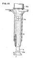
- Fig. 15 illustrates still another embodiment of the ultrasonic atomizing apparatus according to the present invention in which the arrangement is such that a joint 31a between the ultrasonic vibration generating means 30a and the vibrator horn 10 detachably connected to the generating means is at a loop of vibration and the wall of the recess 3 of the horn is formed with a tool (such as allen wrench) engageable socket 32a or other suitable tool engageable groove means, whereby the horn may easily be assembled to the vibration generating means without affecting the atomizing property of the apparatus and it is also made easily to handle the apparatus for transportation.
- a tool such as allen wrench
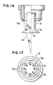
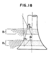
- Figs. 16 to 18 show yet another embodiment of the ultrasonic atomizing apparatus according to this invention.
- a plurality of liquid material supply means 17a (Fig. 17) for feeding liquid material towards the flared section 1a of the vibrator horn 10 are provided in a circular array around the small-diameter section of the horn.
- the illustrated embodiment there are two groups of liquid supply means having their axial feed lines A x and A y intersecting at different angles ⁇ x and ⁇ y , respectively with the longitudinal axis of the horn, whereby one group of liquid supply means directs the liquid against either the small-diameter section or the boundary between the small-diameter section and the flared portion at a first feed point A1 while the other group directs the liquid against the flared portion at a second feed point A2.
- the angles ⁇ x and ⁇ y may be 40° and 20°, respectively.
- a plurality of stages B1 and B2 of atomizing zones are defined on the outer periphery of the flared section of the horn whereby an increased atomizing surface area may be provided over the flared section to thereby permit the horn to atomize liquid to finer droplets and increase the atomizing rate and hence further improve the atomizing property.
- the flared portion of the ultrasonic vibrator horn according to the present invention has been described, as illustrated, as having a trumpet-shaped outer periphery surface, the flared portion may naturally have a conical outer periphery surface.
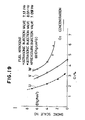
- Fig. 19 shows a combustion characteristics of the ultrasonic atomizing apparatus according to the present invention as applied to a boiler by way of example.
- Fig. 19 in which the ordinate axis is used to represent the smoke scale No.(determinations measured by means of a smoke tester manufactured by Bacharach Company) and the abscissa axis is used to represent the oxygen concentration indicates the comparison results of the combustion characteristics of ultrasonic atomizing in the ultrasonic atomizing apparatus according to the present invention and the combustion characteristics of pressure atomizing in the conventional pressure injection valve.
- the smoke scale No. is obtained by sampling a given amount of the exhaust gas to measure the density of soot and varies corresponding to the change of the soot in amount, which measurement is based on a standard method for measuring soot density prescribed in ASTM Da 15665.
- the combustion characteristics as shown in Fig. 19 represent the combustion characteristics (lines shown by U and V in Fig. 19) of the ultrasonic atomizing apparatus according to the present invention which was applied to a boiler and had an ultrasonic vibrator horn with the slope angle at the tip end of the horn of 25°, the diameter of the small-diameter section of 11 mm and the diameter of the enlarged-diameter section of 24 mm, and the combustion characteristics (line shown by W in Fig. 19) of the conventional pressure injection valve.
- Fig. 19 clearly indicates that the ultrasonic atomizing by the horn according to the invention is superior to that of the conventional horn in combustion characteristics.
- the horn according to the present invention may preferably be applied to various combustion apparatus such as petroleum heaters, boilers and the like.
- ultrasonic atomizing apparatus of the present invention as hereinbefore described with reference to the accompanying drawings is capable of atomizing liquid material more effectively in a short time and in larger quantities, as compared to the prior art apparatus, and yet the atomized droplets are of very small and uniform particle size. Furthermore, it requires a reduced electric power consumption to atomize liquid material, and is capable of feeding liquid material effectively from at least one liquid supply mechanism to the atomizing zone as well as easily controlling, for example, the flow rate of liquid material fed.
- the apparatus is also advantageous from a viewpoint of the strength of material in that the stresses generated in the flared portion of the horn are more uniform.
- the apparatus is capable of atomizing liquid even if it is fed at a rate in excess of the design rate of atomization.
- finer and more uniformly atomized droplets may be provided by varying the compatibility of the liquid material with the surface of the atomizing zone.
- the upper limit of the atomizing rate may be raised by providing a flange at the tip end of the flared portion. Disturbance of the liquid material supplied to the flared portion may be prevented by providing air flow diverting means. Production of soots may be suppressed and cooling effects on the vibrator horn may be enhanced by providing air inlet passage means leading to the hollow recess. Further, it may be made easy to assemble and handle the ultrasonic vibration generating means and the vibrator horn by detachably connecting the two.
- An ultrasonic vibrator horn of the present invention may suitably be used with various ultrasonic atomizing apparatus which atomize the liquid materials by the use of ultrasonic vibration. More particularly, the present invention, as described above, may be effectively used with (a) automobile fuel injection devices such as electronically controlled gasoline injection valves and electronically controlled diesel fuel injection valves, (b) gas turbine fuel nozzles, (c) burners for use on industrial, commercial and domestic boilers, heating furnaces and heating devices, (d) industrial liquid atomizers such as drying atomizers for drying liquid materials such as foods, medicines, agricultural chemicals, fertilizers and the like, spray heads for controlling temperature and humidity, atomizers for calcining powders (pelletizing ceramic), spray coating devices and reaction promoting devices, and (e) liquid atomizers for uses other than industrial ones, such as spreaders for agricultural chemicals and antiseptic solution.
- automobile fuel injection devices such as electronically controlled gasoline injection valves and electronically controlled diesel fuel injection valves
- gas turbine fuel nozzles such as gas turbine fuel nozzles
Landscapes
- Engineering & Computer Science (AREA)
- Chemical & Material Sciences (AREA)
- Combustion & Propulsion (AREA)
- Mechanical Engineering (AREA)
- General Engineering & Computer Science (AREA)
- Special Spraying Apparatus (AREA)
Applications Claiming Priority (12)
| Application Number | Priority Date | Filing Date | Title |
|---|---|---|---|
| JP182755/86 | 1986-08-05 | ||
| JP18275586 | 1986-08-05 | ||
| JP185308/86 | 1986-08-08 | ||
| JP18530986 | 1986-08-08 | ||
| JP18531086 | 1986-08-08 | ||
| JP185309/86 | 1986-08-08 | ||
| JP18530886 | 1986-08-08 | ||
| JP185310/86 | 1986-08-08 | ||
| JP20718386 | 1986-09-03 | ||
| JP207183/86 | 1986-09-03 | ||
| JP139408/86U | 1986-09-12 | ||
| JP13940886 | 1986-09-12 |
Publications (3)
| Publication Number | Publication Date |
|---|---|
| EP0256750A2 true EP0256750A2 (de) | 1988-02-24 |
| EP0256750A3 EP0256750A3 (en) | 1989-06-14 |
| EP0256750B1 EP0256750B1 (de) | 1991-12-04 |
Family
ID=27552913
Family Applications (1)
| Application Number | Title | Priority Date | Filing Date |
|---|---|---|---|
| EP87306892A Expired - Lifetime EP0256750B1 (de) | 1986-08-05 | 1987-08-04 | Ultraschall-Zerstäuber |
Country Status (3)
| Country | Link |
|---|---|
| US (1) | US4799622A (de) |
| EP (1) | EP0256750B1 (de) |
| DE (1) | DE3774959D1 (de) |
Cited By (3)
| Publication number | Priority date | Publication date | Assignee | Title |
|---|---|---|---|---|
| EP0390603A1 (de) * | 1989-03-30 | 1990-10-03 | Tonen Corporation | Kraftstoffversorgungsanlage für einen Brennkraftmotor mit Ultraschallzerstäubung |
| EP0406027A2 (de) * | 1989-06-30 | 1991-01-02 | Tonen Corporation | Steuerverfahren für die Kraftstoffzufuhr und Ultraschallzerstäuber |
| US7926467B2 (en) | 2007-04-30 | 2011-04-19 | Caterpillar Inc. | Droplet generator for engine system |
Families Citing this family (56)
| Publication number | Priority date | Publication date | Assignee | Title |
|---|---|---|---|---|
| JPH0532094Y2 (de) * | 1988-05-17 | 1993-08-18 | ||
| US6540154B1 (en) * | 1991-04-24 | 2003-04-01 | Aerogen, Inc. | Systems and methods for controlling fluid feed to an aerosol generator |
| US6629646B1 (en) | 1991-04-24 | 2003-10-07 | Aerogen, Inc. | Droplet ejector with oscillating tapered aperture |
| US5938117A (en) | 1991-04-24 | 1999-08-17 | Aerogen, Inc. | Methods and apparatus for dispensing liquids as an atomized spray |
| US5219120A (en) * | 1991-07-24 | 1993-06-15 | Sono-Tek Corporation | Apparatus and method for applying a stream of atomized fluid |
| US5449502A (en) * | 1992-12-30 | 1995-09-12 | Sanden Corp. | Sterilizing apparatus utilizing ultrasonic vibration |
| US6782886B2 (en) | 1995-04-05 | 2004-08-31 | Aerogen, Inc. | Metering pumps for an aerosolizer |
| US6205999B1 (en) | 1995-04-05 | 2001-03-27 | Aerogen, Inc. | Methods and apparatus for storing chemical compounds in a portable inhaler |
| US5758637A (en) | 1995-08-31 | 1998-06-02 | Aerogen, Inc. | Liquid dispensing apparatus and methods |
| US6014970A (en) * | 1998-06-11 | 2000-01-18 | Aerogen, Inc. | Methods and apparatus for storing chemical compounds in a portable inhaler |
| US6085740A (en) | 1996-02-21 | 2000-07-11 | Aerogen, Inc. | Liquid dispensing apparatus and methods |
| US6316100B1 (en) * | 1997-02-24 | 2001-11-13 | Superior Micropowders Llc | Nickel powders, methods for producing powders and devices fabricated from same |
| US6338809B1 (en) * | 1997-02-24 | 2002-01-15 | Superior Micropowders Llc | Aerosol method and apparatus, particulate products, and electronic devices made therefrom |
| US6235177B1 (en) | 1999-09-09 | 2001-05-22 | Aerogen, Inc. | Method for the construction of an aperture plate for dispensing liquid droplets |
| KR20020038782A (ko) * | 1999-09-30 | 2002-05-23 | 매튜 디올리티 | 액체혼합물을 냉각하고 그 상태를 변화시키기 위한 방법및 시스템 |
| MXPA02010884A (es) * | 2000-05-05 | 2003-03-27 | Aerogen Ireland Ltd | Aparato y metodo para el suministro de medicamentos al sistema respiratorio. |
| US7100600B2 (en) | 2001-03-20 | 2006-09-05 | Aerogen, Inc. | Fluid filled ampoules and methods for their use in aerosolizers |
| US7971588B2 (en) * | 2000-05-05 | 2011-07-05 | Novartis Ag | Methods and systems for operating an aerosol generator |
| US7600511B2 (en) * | 2001-11-01 | 2009-10-13 | Novartis Pharma Ag | Apparatus and methods for delivery of medicament to a respiratory system |
| US8336545B2 (en) * | 2000-05-05 | 2012-12-25 | Novartis Pharma Ag | Methods and systems for operating an aerosol generator |
| US6948491B2 (en) * | 2001-03-20 | 2005-09-27 | Aerogen, Inc. | Convertible fluid feed system with comformable reservoir and methods |
| US6543443B1 (en) | 2000-07-12 | 2003-04-08 | Aerogen, Inc. | Methods and devices for nebulizing fluids |
| US6546927B2 (en) | 2001-03-13 | 2003-04-15 | Aerogen, Inc. | Methods and apparatus for controlling piezoelectric vibration |
| US6550472B2 (en) | 2001-03-16 | 2003-04-22 | Aerogen, Inc. | Devices and methods for nebulizing fluids using flow directors |
| US6732944B2 (en) * | 2001-05-02 | 2004-05-11 | Aerogen, Inc. | Base isolated nebulizing device and methods |
| US6554201B2 (en) | 2001-05-02 | 2003-04-29 | Aerogen, Inc. | Insert molded aerosol generator and methods |
| US6669103B2 (en) | 2001-08-30 | 2003-12-30 | Shirley Cheng Tsai | Multiple horn atomizer with high frequency capability |
| US7677467B2 (en) * | 2002-01-07 | 2010-03-16 | Novartis Pharma Ag | Methods and devices for aerosolizing medicament |
| US7360536B2 (en) | 2002-01-07 | 2008-04-22 | Aerogen, Inc. | Devices and methods for nebulizing fluids for inhalation |
| US20050205089A1 (en) * | 2002-01-07 | 2005-09-22 | Aerogen, Inc. | Methods and devices for aerosolizing medicament |
| JP4761709B2 (ja) * | 2002-01-15 | 2011-08-31 | エアロジェン,インコーポレイテッド | エアロゾル発生器を作動するための方法およびシステム |
| US6969012B2 (en) * | 2002-01-24 | 2005-11-29 | Kangas Martti Y O | Low pressure atomizer for difficult to disperse solutions |
| ES2572770T3 (es) * | 2002-05-20 | 2016-06-02 | Novartis Ag | Aparato para proporcionar pulverización para tratamiento médico y métodos |
| US20070044792A1 (en) * | 2005-08-30 | 2007-03-01 | Aerogen, Inc. | Aerosol generators with enhanced corrosion resistance |
| JP2004290877A (ja) * | 2003-03-27 | 2004-10-21 | Toyota Motor Corp | 回転霧化塗装装置 |
| US8616195B2 (en) * | 2003-07-18 | 2013-12-31 | Novartis Ag | Nebuliser for the production of aerosolized medication |
| EP1574702B1 (de) * | 2004-03-11 | 2006-06-07 | Delphi Technologies, Inc. | Verfahren zum Zusammenbau eines Kraftstoffeinspritzventils |
| US7267121B2 (en) * | 2004-04-20 | 2007-09-11 | Aerogen, Inc. | Aerosol delivery apparatus and method for pressure-assisted breathing systems |
| JP5175090B2 (ja) * | 2004-04-20 | 2013-04-03 | ノバルティス アーゲー | 従圧式呼吸システム |
| US7290541B2 (en) * | 2004-04-20 | 2007-11-06 | Aerogen, Inc. | Aerosol delivery apparatus and method for pressure-assisted breathing systems |
| US7946291B2 (en) | 2004-04-20 | 2011-05-24 | Novartis Ag | Ventilation systems and methods employing aerosol generators |
| US9108211B2 (en) * | 2005-05-25 | 2015-08-18 | Nektar Therapeutics | Vibration systems and methods |
| KR101069457B1 (ko) * | 2005-05-26 | 2011-09-30 | 혼다덴시 가부시키가이샤 | 초음파 세정장치 |
| US9101949B2 (en) * | 2005-08-04 | 2015-08-11 | Eilaz Babaev | Ultrasonic atomization and/or seperation system |
| US7963458B2 (en) * | 2006-01-23 | 2011-06-21 | Kimberly-Clark Worldwide, Inc. | Ultrasonic liquid delivery device |
| US8191732B2 (en) * | 2006-01-23 | 2012-06-05 | Kimberly-Clark Worldwide, Inc. | Ultrasonic waveguide pump and method of pumping liquid |
| US7810743B2 (en) * | 2006-01-23 | 2010-10-12 | Kimberly-Clark Worldwide, Inc. | Ultrasonic liquid delivery device |
| US7819335B2 (en) * | 2006-01-23 | 2010-10-26 | Kimberly-Clark Worldwide, Inc. | Control system and method for operating an ultrasonic liquid delivery device |
| US8028930B2 (en) * | 2006-01-23 | 2011-10-04 | Kimberly-Clark Worldwide, Inc. | Ultrasonic fuel injector |
| US20080142616A1 (en) * | 2006-12-15 | 2008-06-19 | Bacoustics Llc | Method of Producing a Directed Spray |
| US20090277971A1 (en) * | 2008-05-12 | 2009-11-12 | James Scott | Economical, dripless, reciprocating atomizer |
| WO2009155245A1 (en) | 2008-06-17 | 2009-12-23 | Davicon Corporation | Liquid dispensing apparatus using a passive liquid metering method |
| JP5690451B2 (ja) * | 2012-09-05 | 2015-03-25 | オリンパスメディカルシステムズ株式会社 | 超音波伝達ユニット及び超音波処置装置 |
| DE102013225612B4 (de) | 2013-12-11 | 2017-12-14 | Lechler Gmbh | Injektordüse |
| CN106583139B (zh) * | 2016-12-21 | 2019-11-29 | 杭州瑞利声电技术有限公司 | 一种用于悬浊液的超声波雾化装置 |
| US11872504B2 (en) * | 2021-06-30 | 2024-01-16 | Worcester Polytechnic Institute | Atomizing device for use in a spray dryer |
Citations (5)
| Publication number | Priority date | Publication date | Assignee | Title |
|---|---|---|---|---|
| US3317139A (en) * | 1965-04-13 | 1967-05-02 | Simms Group Res Dev Ltd | Devices for generating and delivering mechanical vibrations to a nozzle |
| US3394274A (en) * | 1964-07-13 | 1968-07-23 | Branson Instr | Sonic dispersing device |
| US3756575A (en) * | 1971-07-19 | 1973-09-04 | Resources Research & Dev Corp | Apparatus for producing a fuel-air mixture by sonic energy |
| GB2073616A (en) * | 1980-04-12 | 1981-10-21 | Leybold Heraeus Gmbh & Co Kg | Apparatus for atomising liquids |
| WO1983001749A1 (en) * | 1981-11-13 | 1983-05-26 | Stigsson, Lars, Lennart | A method for atomizing dispersions or solutions containing particles |
Family Cites Families (36)
| Publication number | Priority date | Publication date | Assignee | Title |
|---|---|---|---|---|
| US578461A (en) * | 1897-03-09 | Emile hertz | ||
| CA752747A (en) * | 1967-02-14 | M. Butterworth Harold | Ultrasonic atomiser | |
| US1659538A (en) * | 1926-08-25 | 1928-02-14 | Burnoyl Heating Corp | Nozzle for liquid-fuel burners |
| US1758119A (en) * | 1927-09-24 | 1930-05-13 | Moon Axel R Le | Lawn-sprinkler nozzle |
| US1730664A (en) * | 1928-11-27 | 1929-10-08 | Kruse William John | Nozzle |
| US2005600A (en) * | 1932-07-28 | 1935-06-18 | Cooling Tower Co Inc | Distributor nozzle |
| US1954173A (en) * | 1932-10-03 | 1934-04-10 | Henry E Pursell | Burner |
| FR786492A (fr) * | 1934-05-23 | 1935-09-03 | Pulvérisateur de liquide | |
| FR803553A (fr) * | 1935-03-22 | 1936-10-03 | Ajutage pour la pulvérisation et la vaporisation complètes des huiles minérales légères et lourdes | |
| US2596341A (en) * | 1945-03-29 | 1952-05-13 | Owens Illinois Glass Co | Burner block and burner |
| DE861344C (de) * | 1948-10-02 | 1952-12-29 | Bosch Gmbh Robert | Einspritzventil fuer Brennkraftmaschinen |
| US2712962A (en) * | 1952-12-11 | 1955-07-12 | Esther C Goddard | Double deflecting spray nozzle |
| US2779623A (en) * | 1954-09-10 | 1957-01-29 | Bernard J Eisenkraft | Electromechanical atomizer |
| US3145931A (en) * | 1959-02-27 | 1964-08-25 | Babcock & Wilcox Ltd | Liquid atomizers generating heat at variable rate through the combustion of liquid fuel |
| SU144826A1 (ru) * | 1960-11-22 | 1961-11-30 | В.Ф. Попов | Прибор дл распылени жидкостей |
| US3110444A (en) * | 1960-12-06 | 1963-11-12 | J S & W R Eakins Inc | Spray drying process and apparatus |
| US3373752A (en) * | 1962-11-13 | 1968-03-19 | Inoue Kiyoshi | Method for the ultrasonic cleaning of surfaces |
| US3749318A (en) * | 1971-03-01 | 1973-07-31 | E Cottell | Combustion method and apparatus burning an intimate emulsion of fuel and water |
| DE2239408A1 (de) * | 1972-08-10 | 1974-02-21 | Eric Charles Cottell | Verfahren und vorrichtung zur herstellung eines kraftstoff-luftgemisches mittels schallenergie |
| SU589031A1 (ru) * | 1972-10-20 | 1978-01-25 | Всесоюзный научно-исследовательский институт применения гражданской авиации в народном хозяйстве | Распылитель жидкости |
| US4153201A (en) * | 1976-11-08 | 1979-05-08 | Sono-Tek Corporation | Transducer assembly, ultrasonic atomizer and fuel burner |
| US4197997A (en) * | 1978-07-28 | 1980-04-15 | Ford Motor Company | Floating ring fuel injector valve |
| US4372491A (en) * | 1979-02-26 | 1983-02-08 | Fishgal Semyon I | Fuel-feed system |
| JPS56107956A (en) * | 1980-01-30 | 1981-08-27 | Hitachi Ltd | Solenoid fuel injection valve |
| FR2488655A2 (fr) * | 1980-08-18 | 1982-02-19 | Rockwell International Corp | Injecteur de carburant equipe d'un clapet de retenue a vibrations ultra-sonores, notamment pour moteur diesel |
| US4350302A (en) * | 1980-09-19 | 1982-09-21 | Zurn Industries, Inc. | Liquid spray nozzle |
| US4408722A (en) * | 1981-05-29 | 1983-10-11 | General Motors Corporation | Fuel injection nozzle with grooved poppet valve |
| US4474326A (en) * | 1981-11-24 | 1984-10-02 | Tdk Electronics Co., Ltd. | Ultrasonic atomizing device |
| US4496101A (en) * | 1982-06-11 | 1985-01-29 | Eaton Corporation | Ultrasonic metering device and housing assembly |
| IT1156079B (it) * | 1982-07-15 | 1987-01-28 | Fiat Ricerche | Dispositivo di intercettamento di un fluido |
| US4541564A (en) * | 1983-01-05 | 1985-09-17 | Sono-Tek Corporation | Ultrasonic liquid atomizer, particularly for high volume flow rates |
| US4690332A (en) * | 1983-11-28 | 1987-09-01 | Nathaniel Hughes | Single inlet prepackaged inhaler |
| JPS60222552A (ja) * | 1984-04-19 | 1985-11-07 | Toa Nenryo Kogyo Kk | 超音波噴射方法 |
| US4607239A (en) * | 1985-02-28 | 1986-08-19 | The United States Of America As Represented By The Secretary Of The Army | Adjustment of the frequency-temperature characteristics of crystal oscillators |
| JPS61259782A (ja) * | 1985-05-13 | 1986-11-18 | Toa Nenryo Kogyo Kk | 多段エツジ部を有する超音波霧化用振動子 |
| DE3534853A1 (de) * | 1985-09-30 | 1987-04-02 | Siemens Ag | Verfahren zum betrieb eines ultraschallzerstaeubers zur fluessigkeitszerstaeubung |
-
1987
- 1987-07-30 US US07/079,742 patent/US4799622A/en not_active Expired - Fee Related
- 1987-08-04 DE DE8787306892T patent/DE3774959D1/de not_active Expired - Lifetime
- 1987-08-04 EP EP87306892A patent/EP0256750B1/de not_active Expired - Lifetime
Patent Citations (5)
| Publication number | Priority date | Publication date | Assignee | Title |
|---|---|---|---|---|
| US3394274A (en) * | 1964-07-13 | 1968-07-23 | Branson Instr | Sonic dispersing device |
| US3317139A (en) * | 1965-04-13 | 1967-05-02 | Simms Group Res Dev Ltd | Devices for generating and delivering mechanical vibrations to a nozzle |
| US3756575A (en) * | 1971-07-19 | 1973-09-04 | Resources Research & Dev Corp | Apparatus for producing a fuel-air mixture by sonic energy |
| GB2073616A (en) * | 1980-04-12 | 1981-10-21 | Leybold Heraeus Gmbh & Co Kg | Apparatus for atomising liquids |
| WO1983001749A1 (en) * | 1981-11-13 | 1983-05-26 | Stigsson, Lars, Lennart | A method for atomizing dispersions or solutions containing particles |
Cited By (4)
| Publication number | Priority date | Publication date | Assignee | Title |
|---|---|---|---|---|
| EP0390603A1 (de) * | 1989-03-30 | 1990-10-03 | Tonen Corporation | Kraftstoffversorgungsanlage für einen Brennkraftmotor mit Ultraschallzerstäubung |
| EP0406027A2 (de) * | 1989-06-30 | 1991-01-02 | Tonen Corporation | Steuerverfahren für die Kraftstoffzufuhr und Ultraschallzerstäuber |
| EP0406027A3 (en) * | 1989-06-30 | 1991-07-24 | Tonen Corporation | Fuel supply control method and ultrasonic atomizer |
| US7926467B2 (en) | 2007-04-30 | 2011-04-19 | Caterpillar Inc. | Droplet generator for engine system |
Also Published As
| Publication number | Publication date |
|---|---|
| DE3774959D1 (de) | 1992-01-16 |
| EP0256750B1 (de) | 1991-12-04 |
| EP0256750A3 (en) | 1989-06-14 |
| US4799622A (en) | 1989-01-24 |
Similar Documents
| Publication | Publication Date | Title |
|---|---|---|
| EP0256750B1 (de) | Ultraschall-Zerstäuber | |
| US4726522A (en) | Vibrating element for ultrasonic atomization having curved multi-stepped edged portion | |
| EP0202844B1 (de) | Schwingungsglied für Ultraschallzerstäubung | |
| EP0196390B1 (de) | Ultraschalleinspritzdüsen | |
| GB2096911A (en) | Atomizer | |
| EP0202381B1 (de) | Verfahren für die Erzeugung von Ultraschallschwingungen und Vorrichtung zur Zerstäubung einer Flüssigkeit | |
| JPS61259782A (ja) | 多段エツジ部を有する超音波霧化用振動子 | |
| US4123481A (en) | Device for carburetion of liquid fuels | |
| JP3192864B2 (ja) | 微粒燃料噴射ノズル | |
| KR20030068564A (ko) | 초음파 연속 유동 연료 분사 장치 및 방법 | |
| EP0251524B1 (de) | Ultraschallzerstäuber | |
| US4844343A (en) | Ultrasonic vibrator horn | |
| KR950013986B1 (ko) | 초음파 무화(霧化)장치 | |
| CA1218395A (en) | Atomizer | |
| JPS63218273A (ja) | 液体霧化装置 | |
| EP0521167A1 (de) | Zerstäuber | |
| JPH0438460B2 (de) | ||
| JPH034954A (ja) | 超音波霧化装置 | |
| KR900003969B1 (ko) | 초음파 분사용 진동자 | |
| JPS63270573A (ja) | 超音波・超音速気流複合噴射弁 | |
| JPH02303569A (ja) | 超音波霧化装置 | |
| JPH02293065A (ja) | 超音波霧化用振動子 | |
| JPH049109B2 (de) | ||
| JPS6294713A (ja) | チエツク弁付超音波噴霧装置 | |
| JPH0332764A (ja) | 超音波霧化装置 |
Legal Events
| Date | Code | Title | Description |
|---|---|---|---|
| PUAI | Public reference made under article 153(3) epc to a published international application that has entered the european phase |
Free format text: ORIGINAL CODE: 0009012 |
|
| AK | Designated contracting states |
Kind code of ref document: A2 Designated state(s): DE FR GB |
|
| PUAL | Search report despatched |
Free format text: ORIGINAL CODE: 0009013 |
|
| AK | Designated contracting states |
Kind code of ref document: A3 Designated state(s): DE FR GB |
|
| 17P | Request for examination filed |
Effective date: 19891125 |
|
| RAP1 | Party data changed (applicant data changed or rights of an application transferred) |
Owner name: TONEN CORPORATION |
|
| 17Q | First examination report despatched |
Effective date: 19910312 |
|
| GRAA | (expected) grant |
Free format text: ORIGINAL CODE: 0009210 |
|
| AK | Designated contracting states |
Kind code of ref document: B1 Designated state(s): DE FR GB |
|
| ET | Fr: translation filed | ||
| REF | Corresponds to: |
Ref document number: 3774959 Country of ref document: DE Date of ref document: 19920116 |
|
| PLBE | No opposition filed within time limit |
Free format text: ORIGINAL CODE: 0009261 |
|
| STAA | Information on the status of an ep patent application or granted ep patent |
Free format text: STATUS: NO OPPOSITION FILED WITHIN TIME LIMIT |
|
| 26N | No opposition filed | ||
| PGFP | Annual fee paid to national office [announced via postgrant information from national office to epo] |
Ref country code: GB Payment date: 19950724 Year of fee payment: 9 |
|
| PGFP | Annual fee paid to national office [announced via postgrant information from national office to epo] |
Ref country code: FR Payment date: 19950809 Year of fee payment: 9 Ref country code: DE Payment date: 19950809 Year of fee payment: 9 |
|
| PG25 | Lapsed in a contracting state [announced via postgrant information from national office to epo] |
Ref country code: GB Effective date: 19960804 |
|
| GBPC | Gb: european patent ceased through non-payment of renewal fee |
Effective date: 19960804 |
|
| PG25 | Lapsed in a contracting state [announced via postgrant information from national office to epo] |
Ref country code: FR Effective date: 19970430 |
|
| PG25 | Lapsed in a contracting state [announced via postgrant information from national office to epo] |
Ref country code: DE Effective date: 19970501 |
|
| REG | Reference to a national code |
Ref country code: FR Ref legal event code: ST |