EP0254881A2 - Thermische Isolierung für Hochdrucksinteröfen - Google Patents
Thermische Isolierung für Hochdrucksinteröfen Download PDFInfo
- Publication number
- EP0254881A2 EP0254881A2 EP87109240A EP87109240A EP0254881A2 EP 0254881 A2 EP0254881 A2 EP 0254881A2 EP 87109240 A EP87109240 A EP 87109240A EP 87109240 A EP87109240 A EP 87109240A EP 0254881 A2 EP0254881 A2 EP 0254881A2
- Authority
- EP
- European Patent Office
- Prior art keywords
- pressure sintering
- thermal insulation
- high pressure
- sintering furnace
- graphite
- Prior art date
- Legal status (The legal status is an assumption and is not a legal conclusion. Google has not performed a legal analysis and makes no representation as to the accuracy of the status listed.)
- Withdrawn
Links
Images
Classifications
-
- B—PERFORMING OPERATIONS; TRANSPORTING
- B30—PRESSES
- B30B—PRESSES IN GENERAL
- B30B11/00—Presses specially adapted for forming shaped articles from material in particulate or plastic state, e.g. briquetting presses, tabletting presses
- B30B11/001—Presses specially adapted for forming shaped articles from material in particulate or plastic state, e.g. briquetting presses, tabletting presses using a flexible element, e.g. diaphragm, urged by fluid pressure; Isostatic presses
- B30B11/002—Isostatic press chambers; Press stands therefor
-
- B—PERFORMING OPERATIONS; TRANSPORTING
- B22—CASTING; POWDER METALLURGY
- B22F—WORKING METALLIC POWDER; MANUFACTURE OF ARTICLES FROM METALLIC POWDER; MAKING METALLIC POWDER; APPARATUS OR DEVICES SPECIALLY ADAPTED FOR METALLIC POWDER
- B22F3/00—Manufacture of workpieces or articles from metallic powder characterised by the manner of compacting or sintering; Apparatus specially adapted therefor ; Presses and furnaces
- B22F3/12—Both compacting and sintering
- B22F3/14—Both compacting and sintering simultaneously
- B22F3/15—Hot isostatic pressing
-
- B—PERFORMING OPERATIONS; TRANSPORTING
- B32—LAYERED PRODUCTS
- B32B—LAYERED PRODUCTS, i.e. PRODUCTS BUILT-UP OF STRATA OF FLAT OR NON-FLAT, e.g. CELLULAR OR HONEYCOMB, FORM
- B32B18/00—Layered products essentially comprising ceramics, e.g. refractory products
-
- C—CHEMISTRY; METALLURGY
- C04—CEMENTS; CONCRETE; ARTIFICIAL STONE; CERAMICS; REFRACTORIES
- C04B—LIME, MAGNESIA; SLAG; CEMENTS; COMPOSITIONS THEREOF, e.g. MORTARS, CONCRETE OR LIKE BUILDING MATERIALS; ARTIFICIAL STONE; CERAMICS; REFRACTORIES; TREATMENT OF NATURAL STONE
- C04B35/00—Shaped ceramic products characterised by their composition; Ceramics compositions; Processing powders of inorganic compounds preparatory to the manufacturing of ceramic products
- C04B35/622—Forming processes; Processing powders of inorganic compounds preparatory to the manufacturing of ceramic products
- C04B35/64—Burning or sintering processes
- C04B35/645—Pressure sintering
-
- F—MECHANICAL ENGINEERING; LIGHTING; HEATING; WEAPONS; BLASTING
- F27—FURNACES; KILNS; OVENS; RETORTS
- F27D—DETAILS OR ACCESSORIES OF FURNACES, KILNS, OVENS OR RETORTS, IN SO FAR AS THEY ARE OF KINDS OCCURRING IN MORE THAN ONE KIND OF FURNACE
- F27D1/00—Casings; Linings; Walls; Roofs
- F27D1/0003—Linings or walls
- F27D1/0033—Linings or walls comprising heat shields, e.g. heat shields
-
- C—CHEMISTRY; METALLURGY
- C04—CEMENTS; CONCRETE; ARTIFICIAL STONE; CERAMICS; REFRACTORIES
- C04B—LIME, MAGNESIA; SLAG; CEMENTS; COMPOSITIONS THEREOF, e.g. MORTARS, CONCRETE OR LIKE BUILDING MATERIALS; ARTIFICIAL STONE; CERAMICS; REFRACTORIES; TREATMENT OF NATURAL STONE
- C04B2237/00—Aspects relating to ceramic laminates or to joining of ceramic articles with other articles by heating
- C04B2237/30—Composition of layers of ceramic laminates or of ceramic or metallic articles to be joined by heating, e.g. Si substrates
- C04B2237/32—Ceramic
- C04B2237/36—Non-oxidic
- C04B2237/363—Carbon
-
- C—CHEMISTRY; METALLURGY
- C04—CEMENTS; CONCRETE; ARTIFICIAL STONE; CERAMICS; REFRACTORIES
- C04B—LIME, MAGNESIA; SLAG; CEMENTS; COMPOSITIONS THEREOF, e.g. MORTARS, CONCRETE OR LIKE BUILDING MATERIALS; ARTIFICIAL STONE; CERAMICS; REFRACTORIES; TREATMENT OF NATURAL STONE
- C04B2237/00—Aspects relating to ceramic laminates or to joining of ceramic articles with other articles by heating
- C04B2237/30—Composition of layers of ceramic laminates or of ceramic or metallic articles to be joined by heating, e.g. Si substrates
- C04B2237/32—Ceramic
- C04B2237/38—Fiber or whisker reinforced
- C04B2237/385—Carbon or carbon composite
-
- C—CHEMISTRY; METALLURGY
- C04—CEMENTS; CONCRETE; ARTIFICIAL STONE; CERAMICS; REFRACTORIES
- C04B—LIME, MAGNESIA; SLAG; CEMENTS; COMPOSITIONS THEREOF, e.g. MORTARS, CONCRETE OR LIKE BUILDING MATERIALS; ARTIFICIAL STONE; CERAMICS; REFRACTORIES; TREATMENT OF NATURAL STONE
- C04B2237/00—Aspects relating to ceramic laminates or to joining of ceramic articles with other articles by heating
- C04B2237/50—Processing aspects relating to ceramic laminates or to the joining of ceramic articles with other articles by heating
- C04B2237/70—Forming laminates or joined articles comprising layers of a specific, unusual thickness
- C04B2237/704—Forming laminates or joined articles comprising layers of a specific, unusual thickness of one or more of the ceramic layers or articles
-
- C—CHEMISTRY; METALLURGY
- C04—CEMENTS; CONCRETE; ARTIFICIAL STONE; CERAMICS; REFRACTORIES
- C04B—LIME, MAGNESIA; SLAG; CEMENTS; COMPOSITIONS THEREOF, e.g. MORTARS, CONCRETE OR LIKE BUILDING MATERIALS; ARTIFICIAL STONE; CERAMICS; REFRACTORIES; TREATMENT OF NATURAL STONE
- C04B2237/00—Aspects relating to ceramic laminates or to joining of ceramic articles with other articles by heating
- C04B2237/50—Processing aspects relating to ceramic laminates or to the joining of ceramic articles with other articles by heating
- C04B2237/84—Joining of a first substrate with a second substrate at least partially inside the first substrate, where the bonding area is at the inside of the first substrate, e.g. one tube inside another tube
Definitions
- the invention relates to thermal insulation for high-pressure sintering furnaces, which surrounds the furnace chamber on all sides within a pressure housing.
- furnaces are required in which corresponding compacts can be sintered and compressed under pressure using a process gas.
- Such a high pressure sintering furnace is described for example in DE-GM 84 31 211.
- This consists of a high-pressure-resistant metal housing in which a thermal insulation surrounds the furnace chamber on all sides, which is made up of a graphite cylinder equipped with heating conductors.
- a thermal insulation surrounds the furnace chamber on all sides, which is made up of a graphite cylinder equipped with heating conductors.
- several layers of graphite felt are used, which shield the pressure housing wall from the heating.
- thermal insulation consists of several alternating layers of graphite felt and gas-tight graphite foil.
- these layers lying one on top of the other are preferably wound endlessly, while several layers are alternately placed one on top of the other in the lid area.
- the graphite felt layers provide thermal insulation, while the graphite foil layers form barrier layers that largely prevent the process gas from passing through. This achieves a more even and constant temperature distribution in the furnace chamber and better energy utilization.
- the pressure housing can be kept thinner.
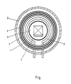
- the figure shows schematically a high-pressure sintering furnace with the thermal insulation according to the invention in cross section.
- the furnace consists of a pressure housing (2) and a graphite cylinder (4) as a boundary of the furnace space (5).
- the heating elements (3) are arranged around the graphite cylinder (4).
- the thermal insulation (1) which is composed of alternating layers of graphite felt and gas-tight graphite foil (7), is located between the pressure housing (2) and the heating elements (3).
Landscapes
- Engineering & Computer Science (AREA)
- Chemical & Material Sciences (AREA)
- Ceramic Engineering (AREA)
- Manufacturing & Machinery (AREA)
- Mechanical Engineering (AREA)
- Inorganic Chemistry (AREA)
- General Engineering & Computer Science (AREA)
- Materials Engineering (AREA)
- Structural Engineering (AREA)
- Organic Chemistry (AREA)
- Physics & Mathematics (AREA)
- Fluid Mechanics (AREA)
- Muffle Furnaces And Rotary Kilns (AREA)
- Furnace Housings, Linings, Walls, And Ceilings (AREA)
- Powder Metallurgy (AREA)
Abstract
Description
- Die Erfindung betrifft eine thermische Isolierung für Hochdrucksinteröfen, die innerhalb eines Druckgehäuses den Ofenraum allseitig umgibt.
- Zur sintermetallurgischen Herstellung von Formkörpern aus Metallen, Keramik oder Metallkeramik benötigt man Öfen, in denen entsprechende Preßlinge gesintert und unter Druck mit Hilfe eines Prozessgases verdichtet werden können.
- Ein solcher Hochdrucksinterofen ist beispielsweise in dem DE-GM 84 31 211 beschrieben. Dieser besteht aus einem hochdruckfesten Metallgehäuse, in dem eine thermische Isolierung allseitig den Ofenraum umgibt, der aus einem mit Heizleitern versehenen Graphitzylinder aufgebaut ist. Zur thermischen Isolierung verwendet man mehrere Lagen Graphitfilz, der die Druckgehäusewand von der Heizung abschirmt.
- Der wenig dichte Aufbau dieses Graphitfilzes erlaubt allerdings den Austausch von heißem Prozessgas vom Ofenraum zur Druckgehäusewand. Energieverluste, Temperaturungleichmäßigkeiten im Ofenraum und eine durch die Erwärmung notwendig verstärkte Druckgehäusewand sind die Folge dieser ungenügenden thermischen Isolierung.
- Es war daher Aufgabe der vorliegenden Erfindung eine thermische Isolierung für Hochdrucksinteröfen zu schaffen, die innerhalb eines Druckgehäuses den Ofenraum allseitig umgibt und die den Austausch von heißem Prozessgas vom Ofenraum zur Druckgehäusewand möglichst weitgehend unterdrückt.
- Diese Aufgabe wurde erfindungsgemäß dadurch gelöst, daß die thermische Isolierung aus mehreren abwechselnden Lagen Graphitfilz und gasdichter Graphitfolie besteht.
- Im zylindrischen Teil des Ofens werden diese aufeinanderliegenden Lagen vorzugsweise endlos gewickelt, während im Deckelbereich mehrere Lagen abwechselnd aufeinandergelegt werden. Die Graphitfilzlagen bewirken hierbei die thermische Isolation, während die Graphitfolienlagen Sperrschichten bilden, die den Prozeßgasdurchtritt weitestgehend verhindern. Man erreicht hiermit eine gleichmäßigere und konstantere Temperaturverteilung im Ofenraum und eine bessere Energieausnutzung. Außerdem kann das Druckgehäuse dünnwandiger gehalten werden.
- Die Abbildung zeigt schematisch einen Hochdrucksinterofen mit der erfindungsgemäß thermischen Isolierung im Querschnitt. Der Ofen besteht aus einem Druckgehäuse (2) und einem Graphitzylinder (4) als Begrenzung des Ofenraums (5). Um den Graphitzylinder (4) sind die Heizelemente (3) angeordnet. Zwischen Druckgehäuse (2) und den Heizelementen (3) befindet sich die thermische Isolierung (1), die sich aus abwechselnden Lagen von Graphitfilz und gasdichter Graphitfolie (7) zusammensetzt.
- Für die Graphitfolie (7) haben sich Schichtdicken von 0,1 bis 1 mm als günstig erwiesen.
Claims (1)
- Thermische Isolierung für Hochdrucksinteröfen, die innerhalb eines Druckgehäuses den Ofenraum allseitig umgibt, dadurch gekennzeichnet, daß sie aus mehreren abwechselnden Lagen Graphitfilz (6) und gasdichter Graphitfolie (7) besteht.
Applications Claiming Priority (2)
| Application Number | Priority Date | Filing Date | Title |
|---|---|---|---|
| DE8620411U | 1986-07-30 | ||
| DE19868620411 DE8620411U1 (de) | 1986-07-30 | 1986-07-30 | Thermische Isolierung für Hochdrucksinteröfen |
Publications (2)
| Publication Number | Publication Date |
|---|---|
| EP0254881A2 true EP0254881A2 (de) | 1988-02-03 |
| EP0254881A3 EP0254881A3 (de) | 1989-05-03 |
Family
ID=6796978
Family Applications (1)
| Application Number | Title | Priority Date | Filing Date |
|---|---|---|---|
| EP87109240A Withdrawn EP0254881A3 (de) | 1986-07-30 | 1987-06-26 | Thermische Isolierung für Hochdrucksinteröfen |
Country Status (5)
| Country | Link |
|---|---|
| EP (1) | EP0254881A3 (de) |
| JP (1) | JPS6329096U (de) |
| DE (1) | DE8620411U1 (de) |
| HU (1) | HUT49701A (de) |
| RO (1) | RO100166B1 (de) |
Families Citing this family (1)
| Publication number | Priority date | Publication date | Assignee | Title |
|---|---|---|---|---|
| US4912302A (en) * | 1987-05-30 | 1990-03-27 | Ngk Insulators, Ltd. | Furnace for sintering ceramics, carbon heater used therefor and process for sintering ceramics |
Family Cites Families (3)
| Publication number | Priority date | Publication date | Assignee | Title |
|---|---|---|---|---|
| DE2328020C3 (de) * | 1972-06-13 | 1981-05-07 | ASEA AB, Västerås | Isoliermantel für den in einer Druckkammer angeordneten Ofenraum einer vertikalen Rohrofenanlage zum isostatischen Heißpressen |
| JPS5893804A (ja) * | 1981-11-30 | 1983-06-03 | Ngk Spark Plug Co Ltd | 加圧焼結炉の断熱壁 |
| JPS58189303A (ja) * | 1982-04-27 | 1983-11-05 | Mitsubishi Heavy Ind Ltd | 垂直円筒炉用断熱壁円筒 |
-
1986
- 1986-07-30 DE DE19868620411 patent/DE8620411U1/de not_active Expired - Lifetime
-
1987
- 1987-06-26 EP EP87109240A patent/EP0254881A3/de not_active Withdrawn
- 1987-07-14 RO RO12906987A patent/RO100166B1/ro unknown
- 1987-07-29 HU HU350787A patent/HUT49701A/hu unknown
- 1987-07-29 JP JP11514487U patent/JPS6329096U/ja active Pending
Also Published As
| Publication number | Publication date |
|---|---|
| JPS6329096U (de) | 1988-02-25 |
| RO100166B1 (en) | 1992-06-11 |
| EP0254881A3 (de) | 1989-05-03 |
| HUT49701A (en) | 1989-10-30 |
| DE8620411U1 (de) | 1986-09-18 |
Similar Documents
| Publication | Publication Date | Title |
|---|---|---|
| DE1539304C3 (de) | Thermoelektrische Vorrichtung | |
| EP0061067A1 (de) | Verfahren zum Einschliessen verbrauchter Brennstäbe eines Kernreaktors in einem Behälter aus Kupfer | |
| DE2327568B2 (de) | Verfahren zur pulvermetallurgischen Herstellung von Schnellstahl | |
| DE2342051C2 (de) | Verfahren zum Sintern eines aus einem eisenhaltigen Metallpulver und Schmiermittel bestehenden Preßkörpers | |
| DE3026324C2 (de) | Ofen für einen Betrieb mit gesteuerter Atmosphäre | |
| DE3621996A1 (de) | Anlage zum waermebehandeln von werkstoffen im vakuum und unter druck | |
| DE2518793A1 (de) | Ausruestung zur behandlung von material bei hoher temperatur und hohem druck | |
| EP0254881A2 (de) | Thermische Isolierung für Hochdrucksinteröfen | |
| EP0255603A2 (de) | Hochdrucksinterofen | |
| DE2328020C3 (de) | Isoliermantel für den in einer Druckkammer angeordneten Ofenraum einer vertikalen Rohrofenanlage zum isostatischen Heißpressen | |
| DE3003459A1 (de) | Industrieofen mit auskleidungsplatten aus keramikfaser | |
| DE2620238B2 (de) | Isoliermantel fuer einen vertikalen druckofen zum isostatischen heisspressen | |
| DE2616555A1 (de) | Zylinderfoermiger langgestreckter ofen zur behandlung von material bei hoher temperatur in einer gasatmosphaere unter hohem druck | |
| DE1945191B2 (de) | Vertikaler rohrofen fuer hohen arbeitsdruck | |
| DE1953306B2 (de) | Vertikaler rohrofen fuer hohen arbeitsdruck | |
| EP0090321A2 (de) | Reaktor und Verfahren zur Herstellung von Halbleitersilicium | |
| DE2616447A1 (de) | Zylinderfoermiger langgestreckter ofen zur behandlung von material bei hoher temperatur in einer gasatmosphaere unter hohem druck | |
| DE3705613A1 (de) | Thermische isolation | |
| DE2158734C3 (de) | Ofen zum Umhüllen von Teilchen bei hoher Temperatur | |
| DE3622668C1 (en) | Fluidised bed kiln for the heat treatment of metallic objects | |
| DE68908908T2 (de) | Vorrichtung zum Trennen von Uranisotopen. | |
| DE1583434C (de) | Vertikaler Rohrofen | |
| DE19923197A1 (de) | Verfahren und Vorrichtung zum Sintern einer Charge von Preßkörpern aus Partikeln | |
| DE2208855C3 (de) | Verfahren zur Herstellung prismatischer Blockbrennelemente für Hochtemperatur-Reaktoren | |
| DE974855C (de) | Einrichtung zur Herstellung von Sinterkoerpern |
Legal Events
| Date | Code | Title | Description |
|---|---|---|---|
| PUAI | Public reference made under article 153(3) epc to a published international application that has entered the european phase |
Free format text: ORIGINAL CODE: 0009012 |
|
| 17P | Request for examination filed |
Effective date: 19870626 |
|
| AK | Designated contracting states |
Kind code of ref document: A2 Designated state(s): AT BE CH DE FR GB IT LI LU NL SE |
|
| PUAL | Search report despatched |
Free format text: ORIGINAL CODE: 0009013 |
|
| AK | Designated contracting states |
Kind code of ref document: A3 Designated state(s): AT BE CH DE FR GB IT LI LU NL SE |
|
| 18W | Application withdrawn |
Withdrawal date: 19891125 |
|
| STAA | Information on the status of an ep patent application or granted ep patent |
Free format text: STATUS: THE APPLICATION HAS BEEN WITHDRAWN |
|
| R18W | Application withdrawn (corrected) |
Effective date: 19891125 |
|
| ITF | It: translation for a ep patent filed | ||
| RIN1 | Information on inventor provided before grant (corrected) |
Inventor name: BONEFF, STOYAN, DR. |