EP0254003B1 - Auf einer unebenen Fläche abstellbare, formstabile Vorrichtung sowie Niveauausgleichselement für diese - Google Patents
Auf einer unebenen Fläche abstellbare, formstabile Vorrichtung sowie Niveauausgleichselement für diese Download PDFInfo
- Publication number
- EP0254003B1 EP0254003B1 EP87108229A EP87108229A EP0254003B1 EP 0254003 B1 EP0254003 B1 EP 0254003B1 EP 87108229 A EP87108229 A EP 87108229A EP 87108229 A EP87108229 A EP 87108229A EP 0254003 B1 EP0254003 B1 EP 0254003B1
- Authority
- EP
- European Patent Office
- Prior art keywords
- piston
- locking member
- locking
- spring
- released position
- Prior art date
- Legal status (The legal status is an assumption and is not a legal conclusion. Google has not performed a legal analysis and makes no representation as to the accuracy of the status listed.)
- Expired - Lifetime
Links
- 238000003780 insertion Methods 0.000 description 10
- 230000037431 insertion Effects 0.000 description 10
- 230000003068 static effect Effects 0.000 description 5
- 238000004519 manufacturing process Methods 0.000 description 4
- 230000000694 effects Effects 0.000 description 3
- 125000006850 spacer group Chemical group 0.000 description 3
- 229910001018 Cast iron Inorganic materials 0.000 description 2
- 229910000831 Steel Inorganic materials 0.000 description 2
- 230000000903 blocking effect Effects 0.000 description 2
- 239000000463 material Substances 0.000 description 2
- 239000010959 steel Substances 0.000 description 2
- 230000006835 compression Effects 0.000 description 1
- 238000007906 compression Methods 0.000 description 1
- 238000010276 construction Methods 0.000 description 1
- 238000011161 development Methods 0.000 description 1
- 230000018109 developmental process Effects 0.000 description 1
- 238000007688 edging Methods 0.000 description 1
- 230000002349 favourable effect Effects 0.000 description 1
- 230000002093 peripheral effect Effects 0.000 description 1
- 238000009420 retrofitting Methods 0.000 description 1
- 239000002023 wood Substances 0.000 description 1
Images
Classifications
-
- A—HUMAN NECESSITIES
- A47—FURNITURE; DOMESTIC ARTICLES OR APPLIANCES; COFFEE MILLS; SPICE MILLS; SUCTION CLEANERS IN GENERAL
- A47B—TABLES; DESKS; OFFICE FURNITURE; CABINETS; DRAWERS; GENERAL DETAILS OF FURNITURE
- A47B91/00—Feet for furniture in general
- A47B91/16—Self-levelling legs
Definitions
- the invention relates to a leveling element for a dimensionally stable device that can be set down on uneven surfaces, such as a piece of furniture.
- DE-B-1 024 220 describes a device for extending the feet of furniture and the like.
- Switching between the release position and the blocking position takes place in the upper end position via a guide rod, which then pulls down a switching element via its upper bent end when it abuts a stop with its lower bent end.
- switching from the locked position to the release position takes place via a shoulder which is integrally formed on the floor support and via a separately latching detent spring which is intended for engagement in a groove on the switching element.
- the actual locking members are designed as clamping wedges and are guided in a conically widening chamfer on the switching member and a spring-loaded washer and are mounted on the piston.
- US-A-2 806 723 already shows the use of a locking ring as a locking member which is canted on the piston. However, there is no possibility here to switch automatically between the release and the locked position, i.e. depending on the piston position. Rather, to release the lock, the release device there is pressed in, otherwise the locking members lock spring-loaded.
- the lower susceptibility to alternating loads results primarily from the fact that by attaching the locking ring with clamping edges against the piston, it is possible to use the piston itself, that is to say areas above and below the locking member, for lateral support. In addition, it is easier to manufacture the compact piston from a stable material, such as the cast iron mentioned, than the sleeve.
- the manufacturing outlay for the level compensation element according to the invention is extremely low. Nevertheless, the operation is very comfortable, because it is only necessary that the piece of furniture is raised once when it is found to be unsafe, then completely lowered and then raised again to the desired position.
- the piston which is spring-loaded in the direction of the leg end is guided in the insert sleeve with a relatively high static friction. This prevents an undesirable adjustment of the level compensation element from occurring when the furniture is slightly shaken.
- the static friction is set so that it is somewhat greater than the spring force of the main spring, but smaller than the sum of the spring force of the main spring and the weight of the piston .
- the auxiliary spring With the force of the main spring and the weight of the piston, the auxiliary spring is compressed in a lower position of the piston and the locking effect of a locking device is overcome.
- the force of the auxiliary spring causes the locking member to automatically lock onto the piston.
- an angle of 5 ° corresponds approximately to a force ratio of 1 to 12 between the force of the auxiliary spring and the clamping force.
- the locking device is designed so that it is able to retain the locking member against the force of the auxiliary spring, but that only by the force of the main spring overcoming the locking action of the locking device and against the force of the auxiliary spring, the locking member from the locked position to the release position can be brought.
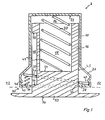
- the drawing shows a vertical section of a level compensation element in a device according to the invention.
- a leveling element 8 shown in FIG. 1 has an insertion sleeve 10 which is sunk in a leg 12 of a device according to the invention, indicated by dashed lines.
- the insertion sleeve 10 has a cylindrical interior 14, in which a piston 16 is slidably guided.
- the play between the piston 16 and the insertion sleeve 10 is shown in greatly enlarged form in FIG. 1.
- the piston 16 has a spring receiving space 18 which points upwards is open and is slightly larger than the diameter of a main spring 20, which exerts pressure between the inner upper end surface 22 of the insertion sleeve 10 and a counter surface 24, which closes the spring receiving space 18 in the piston.
- the insertion sleeve 10 has at its lower end an annular projection 26, which receives a locking member 28 and part of a switching device 30.
- the switching device 30 consists of connection shoulders 32 and 34, an auxiliary spring 36 and a latching device 38.
- the stop shoulders 32 and 34 are each attached to the piston 16 and act on the locking member 28.
- the stop shoulder 32 is designed so that it comes into contact with a part of the locking member 28 in a lower position of the piston 16 near the lowest position and that Locking member 28 moved from a locking position to a release position.
- the stop shoulder 34 is designed such that in an upper position near the uppermost position of the piston 16 it pushes the locking member 28 from the release position into the locking position.
- the auxiliary spring 36 is designed as a compression spring which is supported on the insertion sleeve 10 and presses the locking member 28 in the direction of the locking position.
- the locking device 38 consists of a resilient projection connected to the insertion sleeve 10, which cooperates with a region of the locking member 28 and holds the locking member 28 against the force of the auxiliary spring 36 in the release position when the locking member 28 has been brought into the release position.
- the automatic switching of the locking member 28 into the desired position is possible, the switching from the locking position to the release position when the piston 16 is relatively lowered, i.e. when the device according to the invention is raised, and the switch back to the locking position when the Piston 16 takes place in relation to the leg 12 to an upper position.
- the locking member 28 is annular and surrounds the piston 16. It is pivotally mounted in a space 40 which is provided in the annular extension 26 opposite the switching device 30.
- the locking member 28 is mounted in the space 40 by simple support in the lower outer corner, with an axis or the like. is not required.
- the space 40 is connected to an annular space 42 which extends in the annular extension 26 and which receives the switching device 30 on the side opposite the space 40.
- the locking member 28 can move freely, the dimensions being chosen so that the locking member 28 does not abut the upper inner surface of the annular space 42 even in the locking position, even if the play of the storage of the locking member 28 in the room 40 is relatively large.
- the space 40 is formed by subsequent arching of the insertion sleeve 10 just above the lower outer corner in such a way that the locking member 28 is supported upward, downward and laterally in a substantially U-shaped inner profile of the space 40. However, it must be ensured that the locking member 28 can move freely into the locking position.
- Clamping edges are provided on the inner peripheral surfaces of the annular locking member 28.
- the inner lower edge forms a clamping edge 44 on the side of the locking member 28 close to the space 40, while the inner upper edge forms a clamping edge 46 on the side of the locking member 28 close to the switching device 30.
- the clamping edges are slightly tapered, so that they can develop a better clamping effect compared to opposite and connected to the piston 16 locking surfaces 45 and 47.
- a fine grid can be provided on the blocking surfaces 45 and 47 to further reinforce the clamping effect.
- clamping edge 46 extends in the embodiment shown in FIG. 1 in the area of a groove 48 which is provided in the piston 16 between the stop shoulders 32 and 34, it is possible for this area of the locking member 28, in which the substantially annular Locking member 28 has an inwardly projecting nose 50, not to be equipped with a clamping edge, but the areas of the locking member 28 immediately adjacent to the nose 50, that is to say the area behind and in front of the plane of the drawing in FIG. 1.
- the piston 16 has a base 52 at its lower end, the contact surface 54 of which is slightly convexly rounded.
- This training known per se, enables a relatively low static friction. It is advantageous if the static friction on the leg equipped with the level compensation element according to the invention is less than the static friction on the other legs, so that the mechanics of the level compensation element are not subjected to excessive loads laterally when the piece of furniture is moved.
- a particular advantage of the leveling element according to the invention lies in the retrofitting option, which is simply the making of a hole with a diameter of 10 mm in the middle of the contact surface of the table leg and its additional edging with a file or the like. required to accommodate the annular extension 26.
- the preferred choice of material for the piston 16 is cast iron.
- the locking member 28 can be a stamped sheet steel part, while the insertion sleeve 10 can be made of plastic or steel.
- the groove 48 can also be designed as a passage recess, which creates a connection between the spring receiving space 18 and the annular space 42. However, it must be avoided that the main spring 20 can get caught on the then open upper stop shoulder 32.
- the leveling element according to the invention in devices which have no legs in the narrower sense, but rather a flat contact surface.
- three spacer elements are simply attached to three corners of the contact surface, while the level compensation element according to the invention is attached to the fourth corner.
- the invention can also be used when there are high demands on a wobble-free and stable stand of a piece of furniture or a piece of work equipment.
Landscapes
- Legs For Furniture In General (AREA)
- Road Signs Or Road Markings (AREA)
- Apparatus For Radiation Diagnosis (AREA)
- Pens And Brushes (AREA)
- Particle Formation And Scattering Control In Inkjet Printers (AREA)
- Structures Or Materials For Encapsulating Or Coating Semiconductor Devices Or Solid State Devices (AREA)
Description
- Die Erfindung betrifft ein Niveauausgleichselement für eine auf unebenen Flächen abstellbare, formstabile Vorrichtung wie ein Möbelstück gemäß dem Oberbegriff des Anspruchs 1. Aus der DE-B-1 024 220 ist eine Vorrichtung zur Verlängerung der Standfüsse von Möbeln und dgl. gemäß dem Oberbegriff des Anspruches 1 bereits bekannt. Das Umschalten zwischen der Freigabestellung und der Sperrstellung erfolgt in der oberen Endstellung über eine Führungsstange, die dann über ihr oberes abgebogenes Ende ein Schaltglied herunterzieht, wenn sie mit ihrem unteren abgebogenen Ende an einem Anschlag anstößt. Umgekehrt erfolgt das Umschalten von der Sperrstellung in die Freigabestellung über einen Absatz, der an der Bodenstütze angeformt ist, und über eine separat einrastende Rastfeder, die für den Eingriff in eine Nut an dem Schaltglied bestimmt ist. Die eigentlichen Sperrglieder sind als klemmkeile ausgebildet und in einer sich konusförmig erweiternden Fase an dem Umschaltglied und einer federbelasteten, Unterlegscheibe geführt sowie an dem Kolben gelagert.
- Ferner zeigt die US-A-2 806 723 bereits die Verwendung eines Sperringes als Sperrglied, welcher sich am Kolben verkantet. Hier ist jedoch keine Möglichkeit gegeben, eine Umschaltung zwischen der Freigabe- und der Sperrstellung automatisch, d.h. abhängig von der Kolbenstellung vorzunehmen. Vielmehr wird zur Aufhebung der Sperrung die dortige Lösevorrichtung eingedrückt, während ansonsten die Sperrglieder federbelastet sperren.
- Es ist die Aufgabe der Erfindung, ein Niveauausgleichselement nach dem Oberbegriff des Anspruch 1 zu schaffen, welches sich durch eine einfache und relativ niedrige Bauweise, geringe Herstellungskosten und eine Unanfälligkeit auch bei Wechselbelastungen auszeichnet.
- Diese Aufgabe wird erfindungsgemäß durch das Kennzeichen des Anspruchs 1 gelöst. Vorteilhafte Weiterbildungen ergeben sich aus den Unteransprüchen.
- Die geringere Anfälligkeit gegenüber den Wechselbelastungen ergibt sich vor allem daraus, daß es durch die Anbringung des Sperringes mit Klemmkanten gegen den Kolben möglich ist, den Kolben selbst, also Bereiche oberhalb und unterhalb des Sperrgliedes, zur seitlichen Abstützung zu verwenden. Außerdem ist es einfacher, den kompakten Kolben aus einem stabilen Material, beispielsweise aus dem angesprochenen Gußeisen, herzustellen als die Hülse. Der fertigungstechnische Aufwand für des erfindungsgemäße Niveauausgleichselement ist ausgesprochen gering. Dennoch ist die Bedienung sehr komfortabel, denn es ist nur erforderlich, daß das Möbelstück bei Feststellung eines unsicheren Standes einmal angehoben, dann vollständig abgesenkt und dann erneut in die gewünschte Stellung anagehoben wird.
- Ein weiterer Vorteil ergibt sich, wenn der in Richtung des Beinendes federbelastete Kolben mit relativ großer Haftreibung in der Einsteckhülse geführt ist. Damit wird vermieden, daß bei leichten Erschütterungen des Möbelstücks eine unerwünschte Verstellung des Niveauausgleichselementes auftritt, Vorteilhafterweise wird die Haftreibung so eingestellt, daß sie etwas größer als die Federkraft der Hauptfeder, jedoch kleiner als die Summe aus der Federkraft der Hauptfeder und dem Gewicht des Kolbens ist.
- Mit der Kraft der Hauptfeder und der Gewichtskraft des Kolbens wird in einer unteren Stellung des Kolbens die Hilfsfeder zusammengedrückt und die Sperrwirkung einer Rastvorrichtung überwunden.
- Die Kraft der Hilfsfeder bewirkt die selbsttätige Verklemmung des Sperrgliedes an den Kolben. Bei entsprechend gewähalten Abmessungen ist es möglich, mit einer sehr geringen erforderlichen Federkraft der Hilfsfeder auszukommen, die nur um weniges den auf der Hilfsfeder lastenden Gewichtsanteil des Sperrgliedes übersteigen muß. Dies ist insbesondere dann möglich, wenn der Abstand zwischen den Klemmkanten des Sperrgliedes und den gegenüberstehenden Sperrflächen des Kolbens in der Freigabestellung sehr gering ist. Dann unterscheidet sich die Sperrstellung des Sperrgliedes gegenüber der Freigabestellung nur um wenige Winkelgrade.
- Eine Winkel von 5° entspricht beispielsweise etwa einem Kraftverhältnis von 1 zu 12 zwischen der Kraft der Hilfsfeder und der Klemmkraft.
- Die Rastvorrichtung ist so ausgelegt, daß sie in der Lage ist, das Sperrglied gegen die Kraft der Hilfsfeder zurückzuhalten, daß jedoch allein durch die Kraft der Hauptfeder unter überwindung der Sperrwirkung der Rastvorrichtung und gegen die Kraft der Hilfsfeder das Sperrglied von der Sperrstellung in die Freigabestellung gebracht werden kann.
- Besonders vorteilhaft ist es, wenn die Überwindung der Rastvorrichtung von der Sperrstellung zur Freigabestellung des Sperrgliedes eine erheblich geringere Kraft als die Überwindung der Rastvorrichtung in Gegenrichtung erfordert. Dies kann durch eine einseitig angebrachte, wie eine Führungsfläche arbeitende Abschrägung des mit der Rastvorrichtung in Eingriff stehenden Bereiches des Sperrgliedes verwirklicht werden.
- Weitere Vorteile, Einzelheiten und Merkmale werden in der nachstehenden Beschreibung der Erfindung näher erläutert.
- Die Zeichnung zeigt einen Vertikalschnitt eines Niveauausgleichselementes in einer erfindungsgemäßen Vorrichtung.
- Ein in Fig. 1 dargestelltes Niveauausgleichselement 8 weist eine Einsteckhülse 10 auf, die in einem gestrichelt angedeuteten Bein 12 einer erfindungsgemäßen Vorrichtung versenkt ist. Die Einsteckhülse 10 weist einen zylinderförmigen Innenraum 14 auf, in welchem ein Kolben 16 gleitbeweglich geführt ist. Das Spiel zwischen dem Kolben 16 und der Einsteckhülse 10 ist in Fig. 1 stark vergrößert dargestellt. Der Kolben 16 weist einen Federaufnahmeraum 18 auf, der nach oben offen ist und etwas größer als der Durchmesser einer Hauptfeder 20 ist, die zwischen der inneren oberen Endfläche 22 der Einsteckhülse 10 und einer Gegenfläche 24, die den Federaufnahmeraum 18 in dem Kolben unten abschließt, Druck ausübt.
- Die Einsteckhülse 10 weist an ihrem unteren Ende eine ringförmige Erwieterung 26 auf, die ein Sperrglied 28 und einen Teil einer Umschalteinrichtung 30 aufnimmt. Die Umschalteinrichtung 30 besteht aus Anschlangschultern 32 und 34, einer Hilfsfeder 36 und einer Rastvorrichtung 38.
- Die Anschlagschultern 32 und 34 sind je an dem Kolben 16 angebracht und wirken auf das Sperrglied 28. Die Anschlagschulter 32 ist so ausgebildet, daß sie in einer unteren Stellung des Kolbens 16 nahe der untersten Stellung in Anlage mit einem Teil des Sperrgliedes 28 gerät und das Sperrglied 28 von einer Sperrstellung in eine Freigabestellung bewegt. Die Anschlagschulter 34 ist so ausgelegt, daß sie in einer oberen Stellung nahe der obersten Stellung des Kolbens 16 das Sperrglied 28 von der Freigabestellung in die Sperrstellung drückt.
- Die Hilfsfeder 36 ist als Druckfeder ausgebildet, die sich an der Einsteckhülse 10 abstützt und das Sperrglied 28 in Richtung der Sperrstellung drückt.
- Die Rastvorrichtung 38 besteht aus einem federnden, mit der Einsteckhülse 10 verbundenen Vorsprung, der mit einem Bereich des Sperrgliedes 28 zusammenwirkt und das Sperrglied 28 gegen die Kraft der Hilfsfeder 36 in der Freigabestellung hält, wenn das Sperrglied 28 in die Freigabestellung gebracht worden ist.
- Mit dieser Umschalteinrichtung 30 ist das automatische Umschalten des Sperrgliedes 28 in die gewünschte Stellung möglich, wobei die Umschaltung von der Sperrstellung in die Freigabestellung beim relativen Absenken des Kolbens 16, also beim Anheben der erfindungsgemäßen Vorrichtung, und die Umschaltung zurück in die Sperrstellung beim Anheben des Kolbens 16 gegenüber dem Bein 12 bis in eine obere Stellung erfolgt.
- Das Sperrglied 28 ist ringförmig ausgebildet und umgibt den Kolben 16. Es ist schwenkbeweglich in einem Raum 40 gelagert, der in der ringförmigen Erweiterung 26 gegenüber der Umschalteinrichtung 30 vorgesehen ist. Die Lagerung des Sperrgliedes 28 in dem Raum 40 erfolgt durch einfache Abstützung in der unteren äußeren Ecke, wobei ein Achse o.dgl. nicht erforderlich ist. Der Raum 40 ist mit einem Ringraum 42 verbunden, der sich in der Ringförmigen Erweiterung 26 erstreckt und der an der dem Raum 40 gegenüberliegenden Seite die Umschalteinrichtung 30 aufnimmt. In dem Ringraum 42 kann sich das Sperrglied 28 frei bewegen, wobei die Abmessungen so gewählt sind, daß das Sperrglied 28 auch in der Sperrstellung nicht an der oberen Innenfläche des Ringraumes 42 anliegt, und zwar auch dann nicht, wenn das Spiel der Lagerung des Sperrgliedes 28 in dem Raum 40 relativ groß ist.
- Der Raum 40 ist durch nachträgliche Einwölbung der Einsteckhülse 10 knapp oberhalb der unteren äußeren Ecke so ausgebildet, daß das Sperrglied 28 mit relativ wenig Speil in einem im wesentlichen U-förmigen Innenprofil des Raums 40 nach oben, unten und seitlich abgestützt ist. Es muß jedoch sichergestellt sein, daß sich das Sperrglied 28 frei in die Sperrstellung bewegen kann.
- An den inneneren Umfangsflächen des ringförmigen Sperrgliedes 28 sind Klemmkanten vorgesehen. Dabei bildet an der dem Raum 40 nahen Seite des Sperrgliedes 28 die innere untere Kante eine Klemmkante 44, während an der der Umschalteinrichtung 30 nahen Seite des Sperrgliedes 28 die innere obere Kante eine Klemmkante 46 bildet. Die Klemmkanten sind leicht zugespitzt, so daß sie eine bessere Klemmwirkung gegenüber je gegenüberliegenden und mit dem Kolben 16 verbundenen Sperrflächen 45 und 47 entfalten können.
- Gewünschtenfalls kann an den Sperrflächen 45 und 47 eine feine Rasterung zur weiteren Verstärkung der Klemmwirkung vorgesehen sein.
- Während die Klemmkante 46 sich in dem in Fig. 1 dargestellten Ausführungsbeispiel im Bereich einer Nut 48 erstreckt, die in dem Kolben 16 zwischen den Anschlagschultern 32 und 34 vorgesehen ist, ist es möglich, diesen Bereich des Sperrgliedes 28, in welchem das im wesentlichen ringförmige Sperrglied 28 eine nach innen vorspringende Nase 50 aufweist, nicht mit einer Klemmkante auszustatten, wohl jedoch die der Nase 50 unmittelbar benachbarten Bereiche des Sperrgliedes 28, also die Bereich hinter und vor der Zeichnungsebene der Fig. 1.
- Es ist auch möglich, den Sperring in der Mitte zu lagern. Dies ist jedoch gegenüber dem dargestellten Ausführungsbeispiel nachteilig, da die Hebelverhältnisse ungünstiger werden.
- Der Kolben 16 weist an seinem unteren Ende einen Standfuß 52 auf, dessen Aufstandsfläche 54 leicht konvex abgerundet ist. Diese an sich bekannte Ausbildung ermöglicht eine relativ geringe Haftreibung. Es ist vorteilhaft, wenn die Haftreibung an dem mit dem erfindungsgemäßen Niveauausgleichselement ausgestatteten Bein geringer als die Haftreibung an den anderen Beinen ist, damit die Mechanik des Niveauausgleichselements beim Verschieben des Möbelstücks seitlich nicht zu sehr belastet wird.
- Dadurch, daß an den anderen, nicht mit einem erfindungsgemäßen Niveauausgleichselement ausgestatteten Beinen zusätzliche Distanzelemente vorgesehen sind, die etwa halb so hoch wie der Arbeitshub des Kolbens 16 in der Einsteckhülse 10 ist, wird erreicht, daß bei einem Möbelstück mit vier Beinen lediglich ein Niveauausgleichselement erforderlich ist, und zwar unabhängig davon, auf welche Weise der Boden uneben ist, und unabhängig davon, auf welche Weise das Möbelstück plaziert wird. Die Alternative zu Distanzelementen besteht darin, an zwei einander nicht gegenüberliegenden Beinen erfindungsgemäße Niveauausgleichselemente vorzusehen.
- Ein besonderer Vorteil des erfindungsgemäßen Niveauausgleichselements liegt in der nachträglichen Einbaumöglichkeit, die lediglich die Anbringung einer Bohrung mit 10 mm Durchmesser in der Mitte der Aufstandsfläche des Tischbeines und deren zusätzliche Abfassung mit einer Feile o.dgl. zur Aufnahme der ringförmigen Erweiterung 26 erfordert. Die bevorzugte Materialwahl für den Kolben 16 ist Gußeisen. Das Sperrglied 28 kann ein Stahlblech-Stanzteil sein, während die Einsteckhülse 10 aus Kuntstoff oder aus Stahl bestehen kann.
- In der Ausführungsform gemäß Fig. 1 kann die Nut 48 auch als Durchtrittsausnehmung ausgebildet sein, die eine Verbindung zwischen dem Federaufnahmeraum 18 und dem Ringraum 42 herstellt. Es muß jedoch vermieden werden, daß die Hauptfeder 20 sich an der dann offenliegenden oberen Anschlagschulter 32 verhaken kann.
- Weiterhin ist es möglich, das erfindungsgemäße Niveauausgleichselement bei Vorrichtungen einzusetzen, die keine Beine im engeren Sinne, sonderen eine ebene Aufstandsfläche aufweisen. In diesem Falle werden einfach drei Distanzelemente an drei Ecken der Aufstandsfläche angebracht, während an der vierten Ecke das erfindungsgemäße Niveauausgleichselement angebracht wird.
- Als Alternative zur Anwendung von Distanzelementen kommt es auch in Betracht, das das Niveauausgleichselement tragende Bein beispeilsweise durch Absägen zu verkürzen.
- Obwohl die erfindungsgemäßen Maßnahmen sich besonders günstig bei häufig - absichtlich oder unabsichtlich - zu verschiebenen Möbelstücken wie Tischen, deren sicherer und wackelfreier Stand erwünscht ist, einsetzen läßt, kommt auch der umgekehrte Anwendungsfall in Betracht. Bei der Herstellung von mehr oder weniger komplizierten Gegenständen, die auf mindestens vier Beinen bzw. Abstützflächen stehen sollen, muß bei Verwendung der Erfindung nicht auf die exakte Ebenengleichheit der Abstützflächen geachtet werden. Gleiches gilt für Möbelstücke, die aus jungem Holz hergstellt sind und daher noch "arbeiten", d.h., dazu neigen, sich zu verziehen.
- Insbesondere in der Ausführungsform ohne Rasterung der Sperrflächen 45 und 47 läßt sich die Erfindung auch bei hohen Anforderungen an einen wackelfreien und stabilen Stand eines Möbelstücks oder einer Arbeitsgerätschaft einsetzen.
Claims (9)
Priority Applications (1)
| Application Number | Priority Date | Filing Date | Title |
|---|---|---|---|
| AT87108229T ATE57078T1 (de) | 1986-06-19 | 1987-06-06 | Auf einer unebenen flaeche abstellbare, formstabile vorrichtung sowie niveauausgleichselement fuer diese. |
Applications Claiming Priority (2)
| Application Number | Priority Date | Filing Date | Title |
|---|---|---|---|
| DE3620520A DE3620520C2 (de) | 1986-06-19 | 1986-06-19 | Auf einer unebenen Fläche abstellbare, formstabile Vorrichtung sowie Niveauausgleichselement für diese |
| DE3620520 | 1986-06-19 |
Publications (2)
| Publication Number | Publication Date |
|---|---|
| EP0254003A1 EP0254003A1 (de) | 1988-01-27 |
| EP0254003B1 true EP0254003B1 (de) | 1990-10-03 |
Family
ID=6303246
Family Applications (1)
| Application Number | Title | Priority Date | Filing Date |
|---|---|---|---|
| EP87108229A Expired - Lifetime EP0254003B1 (de) | 1986-06-19 | 1987-06-06 | Auf einer unebenen Fläche abstellbare, formstabile Vorrichtung sowie Niveauausgleichselement für diese |
Country Status (5)
| Country | Link |
|---|---|
| EP (1) | EP0254003B1 (de) |
| AT (1) | ATE57078T1 (de) |
| DE (1) | DE3620520C2 (de) |
| ES (1) | ES2018205B3 (de) |
| GR (1) | GR3000933T3 (de) |
Families Citing this family (9)
| Publication number | Priority date | Publication date | Assignee | Title |
|---|---|---|---|---|
| GB2225715A (en) * | 1988-12-08 | 1990-06-13 | Christopher Brown | Anglers bed chair |
| GB9116354D0 (en) * | 1991-07-29 | 1991-09-11 | R J C U K Limited | Telescopic adjustable leg |
| US5490648A (en) * | 1993-06-07 | 1996-02-13 | Cullen; Christopher P. | Mechanical stabilizer |
| GB2327872B (en) * | 1996-10-23 | 1999-03-24 | Fox Design Int | Adjustable leg |
| GB2365761A (en) * | 2000-08-12 | 2002-02-27 | Chub Leisure Ltd | Adjustable telescopic strut |
| DE202005007317U1 (de) * | 2005-05-09 | 2006-09-21 | Rixen, Wolfgang, Dipl.-Ing. | Vorrichtung für einen automatischen Höhenausgleich |
| DE102005024850A1 (de) * | 2005-05-27 | 2006-12-07 | Johan Lefferts | Niveau-Ausgleichsvorrichtung für Möbelstücke |
| DE202006003232U1 (de) | 2006-03-01 | 2006-06-08 | Mafell Ag | Höhenverstellung für Tisch |
| GB2560178A (en) * | 2017-03-01 | 2018-09-05 | Fox International Group Ltd | An adjustable leg, and an article with an adjustable leg |
Family Cites Families (9)
| Publication number | Priority date | Publication date | Assignee | Title |
|---|---|---|---|---|
| FR814589A (fr) * | 1936-03-05 | 1937-06-25 | Cale automatique pour meubles et autres objets | |
| US2204077A (en) * | 1936-10-07 | 1940-06-11 | Eriksson Frans Wiktor | Leg for furniture |
| DE1024220B (de) * | 1952-11-17 | 1958-02-13 | Anton Lautenbacher | Selbsttaetig wirkende Vorrichtung zur Verlaengerung, insbesondere zum Laengenausgleich der Standfuesse von Moebeln, Staendern, Geruesten, Leitern u. dgl. |
| DE1094949B (de) * | 1952-11-18 | 1960-12-15 | Edmund Leichnitz | Selbsttaetig wirksames Geraet zum Ausgleich von Bodenunebenheiten fuer Moebel und andere Gegenstaende |
| US2775849A (en) * | 1953-07-16 | 1957-01-01 | Frank W Ingram | Furniture stabilizing device |
| US2806723A (en) * | 1955-06-16 | 1957-09-17 | Thomas H Fairclough | Telescopic support device |
| DE1162047B (de) * | 1961-08-08 | 1964-01-30 | Edmund Leichnitz | Selbsttaetig wirksames Geraet zum Ausgleich von Bodenunebenheiten fuer Moebel und andere Gegenstaende |
| DE1273150B (de) * | 1961-09-08 | 1968-07-18 | Kurt Artmann | Ausgleichsvorrichtung fuer Hoehendifferenzen bei Moebelbeinen |
| US3144234A (en) * | 1961-09-08 | 1964-08-11 | Artmann Kurt | Support structure for furniture and the like |
-
1986
- 1986-06-19 DE DE3620520A patent/DE3620520C2/de not_active Expired - Fee Related
-
1987
- 1987-06-06 ES ES87108229T patent/ES2018205B3/es not_active Expired - Lifetime
- 1987-06-06 AT AT87108229T patent/ATE57078T1/de not_active IP Right Cessation
- 1987-06-06 EP EP87108229A patent/EP0254003B1/de not_active Expired - Lifetime
-
1990
- 1990-10-12 GR GR90400766T patent/GR3000933T3/el unknown
Also Published As
| Publication number | Publication date |
|---|---|
| ES2018205B3 (es) | 1991-04-01 |
| DE3620520A1 (de) | 1987-12-23 |
| ATE57078T1 (de) | 1990-10-15 |
| DE3620520C2 (de) | 1995-02-02 |
| GR3000933T3 (en) | 1991-12-10 |
| EP0254003A1 (de) | 1988-01-27 |
Similar Documents
| Publication | Publication Date | Title |
|---|---|---|
| DE10116821B4 (de) | Verstellbare Armlehnenanordnung mit einem einzigen Verstellhebel | |
| DE29908098U1 (de) | Hebevorrichtung für eine Flüssigkristall-Anzeigeeinrichtung | |
| DE112013007025B4 (de) | Verriegelungsvorrichtung für teleskopierbare Möbelsäule, Möbel und Verfahren | |
| DE3430737A1 (de) | Stativ fuer eine kamera oder fuer ein anderes optisches geraet | |
| DE102008062774A1 (de) | Türschutzgitter | |
| EP0641532A1 (de) | Längenverstellbare Säule für Stühle, Tische o.dgl. | |
| DE3341402A1 (de) | Verriegelbares dreibeinstativ-bein | |
| DE3613005A1 (de) | Metalltisch | |
| DE3620520C2 (de) | Auf einer unebenen Fläche abstellbare, formstabile Vorrichtung sowie Niveauausgleichselement für diese | |
| EP0369319B1 (de) | Tisch mit verstellbarer Tischplatte | |
| DE3342169C2 (de) | Tisch | |
| DE69716267T2 (de) | Stabilisierungseinrichtung | |
| DE102021214820B4 (de) | Verbindungsanordnung und Bürostuhl | |
| DE3301467C2 (de) | Trägeranordnung für ein Datensichtgerät | |
| EP1694161A1 (de) | Schrägstellvorrichtung für möbelstücke | |
| DE8333532U1 (de) | Tisch | |
| EP1374727A1 (de) | Schrägstellvorrichtung für Möbelstücke | |
| EP0580077B1 (de) | Tisch mit einer beweglichen Arbeitsplatte | |
| DE3902828A1 (de) | Stativ | |
| DE19934484B4 (de) | Eine kompakte in kleiner Bauweise höhenverstellbare Säule, insbesondere für Tisch und Arbeitsplatten | |
| EP2883475B1 (de) | Tischunterkonstruktion | |
| DE3018216A1 (de) | Arbeitstisch mit hoehenverstellbarer tischplatte | |
| DE602005000322T2 (de) | Eine herausziehbare Fläche | |
| DE4124735C2 (de) | ||
| DE29909591U1 (de) | Tisch |
Legal Events
| Date | Code | Title | Description |
|---|---|---|---|
| PUAI | Public reference made under article 153(3) epc to a published international application that has entered the european phase |
Free format text: ORIGINAL CODE: 0009012 |
|
| AK | Designated contracting states |
Kind code of ref document: A1 Designated state(s): AT BE CH ES FR GB GR IT LI LU NL SE |
|
| 17P | Request for examination filed |
Effective date: 19880218 |
|
| 17Q | First examination report despatched |
Effective date: 19890623 |
|
| GRAA | (expected) grant |
Free format text: ORIGINAL CODE: 0009210 |
|
| AK | Designated contracting states |
Kind code of ref document: B1 Designated state(s): AT BE CH ES FR GB GR IT LI LU NL SE |
|
| PG25 | Lapsed in a contracting state [announced via postgrant information from national office to epo] |
Ref country code: GR Free format text: LAPSE BECAUSE OF FAILURE TO SUBMIT A TRANSLATION OF THE DESCRIPTION OR TO PAY THE FEE WITHIN THE PRESCRIBED TIME-LIMIT Effective date: 19901003 |
|
| REF | Corresponds to: |
Ref document number: 57078 Country of ref document: AT Date of ref document: 19901015 Kind code of ref document: T |
|
| GBT | Gb: translation of ep patent filed (gb section 77(6)(a)/1977) | ||
| ET | Fr: translation filed | ||
| ITF | It: translation for a ep patent filed | ||
| REG | Reference to a national code |
Ref country code: GR Ref legal event code: FG4A Free format text: 3000933 |
|
| ITTA | It: last paid annual fee | ||
| PG25 | Lapsed in a contracting state [announced via postgrant information from national office to epo] |
Ref country code: LU Free format text: LAPSE BECAUSE OF NON-PAYMENT OF DUE FEES Effective date: 19910630 Ref country code: LI Effective date: 19910630 Ref country code: CH Effective date: 19910630 Ref country code: BE Effective date: 19910630 |
|
| PLBE | No opposition filed within time limit |
Free format text: ORIGINAL CODE: 0009261 |
|
| STAA | Information on the status of an ep patent application or granted ep patent |
Free format text: STATUS: NO OPPOSITION FILED WITHIN TIME LIMIT |
|
| 26N | No opposition filed | ||
| BERE | Be: lapsed |
Owner name: HAFELE K.G. Effective date: 19910630 |
|
| PG25 | Lapsed in a contracting state [announced via postgrant information from national office to epo] |
Ref country code: NL Effective date: 19920101 |
|
| NLV4 | Nl: lapsed or anulled due to non-payment of the annual fee | ||
| REG | Reference to a national code |
Ref country code: CH Ref legal event code: PL |
|
| PGFP | Annual fee paid to national office [announced via postgrant information from national office to epo] |
Ref country code: FR Payment date: 19930514 Year of fee payment: 7 |
|
| PGFP | Annual fee paid to national office [announced via postgrant information from national office to epo] |
Ref country code: GB Payment date: 19930518 Year of fee payment: 7 |
|
| PGFP | Annual fee paid to national office [announced via postgrant information from national office to epo] |
Ref country code: AT Payment date: 19930521 Year of fee payment: 7 |
|
| PGFP | Annual fee paid to national office [announced via postgrant information from national office to epo] |
Ref country code: ES Payment date: 19930604 Year of fee payment: 7 |
|
| PGFP | Annual fee paid to national office [announced via postgrant information from national office to epo] |
Ref country code: SE Payment date: 19930623 Year of fee payment: 7 |
|
| PG25 | Lapsed in a contracting state [announced via postgrant information from national office to epo] |
Ref country code: GB Effective date: 19940606 Ref country code: AT Effective date: 19940606 |
|
| PG25 | Lapsed in a contracting state [announced via postgrant information from national office to epo] |
Ref country code: SE Effective date: 19940607 Ref country code: ES Free format text: LAPSE BECAUSE OF EXPIRATION OF PROTECTION Effective date: 19940607 |
|
| REG | Reference to a national code |
Ref country code: GR Ref legal event code: MM2A Free format text: 3000933 |
|
| EUG | Se: european patent has lapsed |
Ref document number: 87108229.3 Effective date: 19950110 |
|
| GBPC | Gb: european patent ceased through non-payment of renewal fee |
Effective date: 19940606 |
|
| PG25 | Lapsed in a contracting state [announced via postgrant information from national office to epo] |
Ref country code: FR Effective date: 19950228 |
|
| EUG | Se: european patent has lapsed |
Ref document number: 87108229.3 |
|
| REG | Reference to a national code |
Ref country code: FR Ref legal event code: ST |
|
| REG | Reference to a national code |
Ref country code: ES Ref legal event code: FD2A Effective date: 19990601 |
|
| PG25 | Lapsed in a contracting state [announced via postgrant information from national office to epo] |
Ref country code: IT Free format text: LAPSE BECAUSE OF NON-PAYMENT OF DUE FEES;WARNING: LAPSES OF ITALIAN PATENTS WITH EFFECTIVE DATE BEFORE 2007 MAY HAVE OCCURRED AT ANY TIME BEFORE 2007. THE CORRECT EFFECTIVE DATE MAY BE DIFFERENT FROM THE ONE RECORDED. Effective date: 20050606 |