EP0253809B1 - Zusammenlegbare fahrräder mit dreieckförmigen gestellen - Google Patents
Zusammenlegbare fahrräder mit dreieckförmigen gestellen Download PDFInfo
- Publication number
- EP0253809B1 EP0253809B1 EP86901451A EP86901451A EP0253809B1 EP 0253809 B1 EP0253809 B1 EP 0253809B1 EP 86901451 A EP86901451 A EP 86901451A EP 86901451 A EP86901451 A EP 86901451A EP 0253809 B1 EP0253809 B1 EP 0253809B1
- Authority
- EP
- European Patent Office
- Prior art keywords
- strut
- struts
- wheels
- bicycle
- further characterised
- Prior art date
- Legal status (The legal status is an assumption and is not a legal conclusion. Google has not performed a legal analysis and makes no representation as to the accuracy of the status listed.)
- Expired
Links
- XAGFODPZIPBFFR-UHFFFAOYSA-N aluminium Chemical compound [Al] XAGFODPZIPBFFR-UHFFFAOYSA-N 0.000 description 2
- 229910052782 aluminium Inorganic materials 0.000 description 2
- 239000004411 aluminium Substances 0.000 description 2
- 239000004677 Nylon Substances 0.000 description 1
- 239000003365 glass fiber Substances 0.000 description 1
- 239000000463 material Substances 0.000 description 1
- 238000000034 method Methods 0.000 description 1
- 238000012986 modification Methods 0.000 description 1
- 230000004048 modification Effects 0.000 description 1
- 229920001778 nylon Polymers 0.000 description 1
- 239000004033 plastic Substances 0.000 description 1
- 229920003023 plastic Polymers 0.000 description 1
- 239000007787 solid Substances 0.000 description 1
- 239000003351 stiffener Substances 0.000 description 1
Images


Classifications
-
- B—PERFORMING OPERATIONS; TRANSPORTING
- B62—LAND VEHICLES FOR TRAVELLING OTHERWISE THAN ON RAILS
- B62K—CYCLES; CYCLE FRAMES; CYCLE STEERING DEVICES; RIDER-OPERATED TERMINAL CONTROLS SPECIALLY ADAPTED FOR CYCLES; CYCLE AXLE SUSPENSIONS; CYCLE SIDE-CARS, FORECARS, OR THE LIKE
- B62K15/00—Collapsible or foldable cycles
- B62K15/006—Collapsible or foldable cycles the frame being foldable
- B62K15/008—Collapsible or foldable cycles the frame being foldable foldable about 2 or more axes
Definitions
- This invention relates to bicycles which may be collapsed into a folded state wherein they will occupy less space for storage or transportation.
- a number of bicycles having folding frame structures have been proposed in the past and although they reduce the space occupied by the bicycle to a more compact volume, generally existing folding bicycles are such that, in the folded state, they are still relatively bulky. Furthermore most folding bicycles are difficult to carry and it can be very fatiguing for the user to carry the folded bicycle for any distance.
- DE-C-115 840 discloses a bicycle according to the preamble of claim 1.
- this invention provides a collapsible bicycle comprising a triangular frame formed , from the interlinking of a forward strut, a rear strut, and a generally horizontal bottom strut which is connected to the other two struts at or near their lower ends, a wheel mounted at or near the lower ends of each of the forward and rear struts by supports, each of which is offset from the axis of the respective strut, whilst the upper ends of the forward and rear struts are interconnected in such a way that these two struts can be moved to lie alongside one another, after releasing a frame locking member on the bottom strut, so that the two wheels will lie side by side and with their respective offset supports positioned at opposite sides of the pair of wheels.
- the simple triangular structure for the frame and the method of interlinking of the three struts enables the framework to be collapsed down to a very compact state wherein the struts are very close to one another with their longitudinal axes generally parallel and with the wheels close to one another.
- the wheels should incorporate mutually engaging releasable locking members enabling the wheels to be interengaged, when lying alongside one another, so that they rotate about a common axis.
- Such a structure then takes the form generally of an elongated shaft carrying a double wheel at one end. Not only is this structure very compact but it also enables the user to transport the folded bicycle by grasping an upper portion of the folded frame members and wheeling the unit along the ground by means of the interlinked wheels.
- the bottom strut is detachable from one of the other two struts and- pivotally connected to the other of the two struts enabling the released bottom strut to be swung up alongside the other strut.
- the bottom strut will be connected to the forward strut by a pivot arrangement allowing the forward strut to rotate about its axis relative to the bottom strut.
- the upper ends of the forward and rear struts can be interconnected by a swivel joint allowing the forward strut to rotate about its axis relative to the rear strut also, the forward strut then acts as a steering member for the bicycle.
- the swivel joint will also interconnect the front and rear struts in the manner enabling them to be moved to lie alongside one another.
- the pivot arrangement advantageously comprises a releasable pivot pin and socket interconnection also providing the locking member.
- the pivot arrangement may be interengaged by a releasable catch operated by a lever or other pressure release member.
- the mounting of the pivot arrangement on the forward strut should be adjustable.
- Another possibility is to provide that the pivot arrangement is slidably received on the forward strut so that, after release of the locking member, it may be slid up the forward strut as the forward strut is moved to lie alongside the rear strut.
- Another alternative is to provide a locking member in the form of a lockable hinge at a central position of the bottom strut with the ends of the bottom strut pivotally interconnected to the other two struts.
- the bicycle may incorporate further frame members acting as stiffeners or strain bearing members between the three struts.
- a mounting on the rear strut carries a saddle.
- the mounting for the saddle must be adjustably secured to the rear strut and may also provide an attachment for a carrier for the bicycle.
- a support carrying handlebars should be mounted on the forward strut.
- Brake cables may lead from brake levers on the handlebars to brakes on one or both of the two wheels.
- Each brake may be a drum brake within the hub of the wheel.
- Drive pedals are desirably mounted on the bottom strut and connected to drive one of the wheels.
- the drive member from the pedals to the wheel could be a belt or chain, and the drive pedals can be connected to a drive pulley or cog which incorporates a freewheel unit and/or a gearbox. If desired a drive motor could be connected to drive one of the wheels.
- the offset supports from the wheels will carry cantilevered axles on which the wheels are rotatably mounted.
- the bicycle shown in Figure 1 is essentially constructed from a triangular frame formed by a rear strut A, a forward strut B and a bottom strut C.
- the lower end of the forward strut B provides an axle 1 for a front wheel W1 whilst the rear strut A provides, at its lower end, an axle 2 for a wheel W2.
- Mounted on the bottom strut C is a front pulley 3 provided with pedal cranks K and pedals P.
- This front pulley 3 is interconnected with a rear pulley 4, which drives the rear wheel W2, by a toothed drive belt D.
- a freewheel unit 5 is provided at the centre of the front pulley 3.
- a saddle S is mounted on the rear strut A and handlebars H are mounted at the top of the forward strut B.
- a releasable steering joint J enables the bottom strut C to be detached from the forward strut B and swung up to lie alongside the rear strut A.
- the forward strut B can then be swung back into alignment with the rear strut A so that the wheels W1 and W2 are brought into alignment as illustrated in Figure 2.
- the bicycle In this compact state the bicycle can be stowed in a small space or can be wheeled along using the support 6 for the handlebars H as a handle. This is illustrated in Figure 4, whilst Figure 3 shows the bicycle in its normal condition and in use.
- the rear and forward struts A and B incorporate cranked portions 7 and 8 at their lower ends leading to supports 9 and 10 on which are mounted the rear axle 2 and the front axle 1.
- This offsetting of the supports for the wheels W1 and W2 enables the wheels to be aligned very closely to one another so that, in the folded state, the bicycle has a compact width.
- the bottom strut C is not shown in Figure 2A but this also incorporates a cranked portion 15 leading to an offset support 16 located about the rear axle 2.
- the hub 11 of the rear wheel W2 carries a resilient collar 12.
- the hub 13 of the front wheel W1 carries a stud 14 which can be pushed, as a snap fit, into the collar 12 to link the hubs 11 and 13 together. This locks the bicycle in its folded condition and allows the two wheels W1 and W2 to be wheeled along about the same axis. When the bicycle is to be reverted to its normal condition the wheels W1 and W2 are prised apart so that the stud 14 snaps out of the collar 12.
- Figure 5 also illustrates additional features of the mountings of the wheels W1 and W2 to the ends of the rear and forward struts A and B.
- the front axle is securely fitted into a front end cap 17 fixed into the lower end of the forward strut B and is mounted within the wheel W1 by a standard bicycle cup and cone bearing 18.
- a brake drum 19 is fitted into the hub of the wheel W1 and a brake back plate assembly 20 carries a brake actuator 21 which operates brake shoes 22.
- the rear pulley 4 is mounted on the wheel hub 11 of the wheel W2 and also acts as a brake drum which incorporates brake shoes 23 actuated by a separate brake actuator (not shown).
- the rear axle 2 is mounted in an end cap 24 fixed within the end of the bottom strut C. The rear axle 2 then passes through a solid end member 25 (see also Figure 1) fitted into the end of the rear strut A.
- Figure 6 illustrates particular features of the support 6 providing a mounting for the handlebars H.
- This support also has the forward strut B fixed therein and at its upper corner provides a socket joint 26 for a ball 27 having an extension 28 which is secured within the top of the rear strut A.
- the ball and socket joint 26, 27 allows the struts A and B to be rotated relative to one another so that the rear strut A can be moved into the position illustrated in dashed outline, adjacent to the forward strut B, when the bicycle is being put into its folded position.
- the ball and socket joint 26, 27 also allows the forward strut B to rotate and act as a steering shaft (with respect to the rest of the bicycle) for the front wheel W1.
- the forward strut B also rotates with respect to the joint J.
- this joint J comprises a sleeve 29 fixed to the forward strut B by clamping screws 30 and carrying a steering pin 31 received within a front bush 32 extending from the end of the bottom strut C.
- a resilient finger 33 can be pressed upwardly to release a catch 34 from a collar 35 on the steering pin 31 when the bottom strut C is to be disengaged from the forward strut B.
- the steering axis 36A of the front strut B is displaced from the axis 36B of the steering pin 31 which provides a suitable offset which then provides the necessary trail for the front wheel W1 during steering.
- Figure 6 also illustrates a pair of brake cables 37, 38 which lead through the support 6 to brake levers (not shown) carried by the handlebars H.
- the cable 37 leads down through the forward strut B to the brake actuator 21 for the front wheel W1 whilst the other cable 38 leads down through the rear strut A to the brake actuator for the rear wheel W2.
- the saddle S is mounted on a sleeve support 39 which is fixed by clamps 40 onto the rear strut A.
- the clamps 40 can be released to allow the sleeve support 39 to be slid to a desired position on the rear strut A to suit a particular person. Further adjustment of the overall relationship of the parts of the bicycle can be achieved by releasing the clamp screws 30 and moving the joint J to a new position relative to the forward strut B.
- the struts A, B and C will be formed from aluminium tubing and other parts can be formed from diecast aluminium or rigid plastics materials, for example.
- the drive belt D will desirably be a dry glass fibre reinforced belt faced with nylon but it will be appreciated that, for some purposes, a chain drive may be preferred. It is envisaged that when the bicycle is in its folded condition the bottom strut C will fit against the forward strut B or into the valley formed by the struts A and B. If necessary, however, an additional clip may be provided to hold the bottom strut C in place when the bicycle is in the folded condition.
- a bag or shopping support could be. provided for attachment to the support sleeve 39 below the saddle S.
- the bicycle could also incorporate gears, such as in the form of an epicyclic gearbox mounted in the front pulley 3. It is also envisaged that the bicycle could be provided with electric power by means of a simple motor and battery system driving the front wheel.
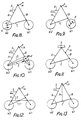
- Figure 8 shows mounting of the drive cranks K co-axially with or near to the rear wheel mounting and driving the rear wheel W2 whilst Figure 9 shows the cranks K mounted co-axially with or near to the front wheel mounting and driving the front wheel W1.
- Figure 10 shows an embodiment in which the cranks K are mounted on or near the bottom joint between the steering strut B and the bottom strut C driving front or rear wheels.
- Figure 11 shows how the seat can be mounted directly on the upper joint between the rear strut A and the steering strut B.
- Figure 12 shows the provision of two bottom struts C1 and C2 for added rigidity when the bicycle is in use.
- a tension wire T is added between a point on the bottom strut C and the upper joint connecting struts A and B to provide additional strength.
- Figure 14 shows an embodiment in which the bottom member is in two pieces and supported by a tension member T.
- Figure 15 shows the steering strut B extended beyond the upper joint connecting the struts A and B so that the handlebars H can be mounted on the upper extension.
- Figures 16 to 19 show variations of how the folding struts A, B and C come apart from each other at some or all of the joints shown. They will then be laid alongside one another to form the compact folded structure similar to that of Figure 2.
- Figure 20 shows the joint between the struts B and C remaining attached but slidable as the two struts A and B are folded towards one another.
- Figure 21 shows a hinge M approximately midway of the strut C so that this strut C can fold upwardly or downwardly as required.
- Figures 22 to 25 show variations in the rear wheel attachment.
- the rear strut is extended downwardly from the hub of the wheel W2 to form an attachment for the rear end of the bottom strut C
- Figure 23 shows the rear end of the bottom strut C extending beyond the wheel hub of wheel W2 to join the rear strut A.
- Figure 24 shows the attachment of the bottom member C to the rear strut A and the steering strut B, in both instances at points above the connection of the other two struts to the hubs of wheels W2 and W1.
- Figure 25 shows an alternative embodiment in which the bottom strut C is attached to the steering strut B above the lower connection of strut B with the hub of the wheel W1, whilst the lower end of the rear strut A is connected at a point forward of the connection of the rear end of the member C to the hub of wheel W2.
- the handlebars can be of any suitable shape and could be made as folding structures. Thus they can be adjustable in height and angle and foldable inwardly or outwardly of the plane of the frame or alternatively swing into a vertical plane.
Landscapes
- Engineering & Computer Science (AREA)
- Mechanical Engineering (AREA)
- Motorcycle And Bicycle Frame (AREA)
- Transition And Organic Metals Composition Catalysts For Addition Polymerization (AREA)
- Organic Low-Molecular-Weight Compounds And Preparation Thereof (AREA)
- Handcart (AREA)
- Steering Devices For Bicycles And Motorcycles (AREA)
Claims (10)
Priority Applications (1)
| Application Number | Priority Date | Filing Date | Title |
|---|---|---|---|
| AT86901451T ATE44695T1 (de) | 1985-02-27 | 1986-02-24 | Zusammenlegbare fahrraeder mit dreieckfoermigen gestellen. |
Applications Claiming Priority (2)
| Application Number | Priority Date | Filing Date | Title |
|---|---|---|---|
| GB858505070A GB8505070D0 (en) | 1985-02-27 | 1985-02-27 | Folding/demountable bicycles |
| GB8505070 | 1985-02-27 |
Publications (2)
| Publication Number | Publication Date |
|---|---|
| EP0253809A1 EP0253809A1 (de) | 1988-01-27 |
| EP0253809B1 true EP0253809B1 (de) | 1989-07-19 |
Family
ID=10575173
Family Applications (1)
| Application Number | Title | Priority Date | Filing Date |
|---|---|---|---|
| EP86901451A Expired EP0253809B1 (de) | 1985-02-27 | 1986-02-24 | Zusammenlegbare fahrräder mit dreieckförmigen gestellen |
Country Status (10)
| Country | Link |
|---|---|
| US (1) | US4718688A (de) |
| EP (1) | EP0253809B1 (de) |
| JP (1) | JPH0717222B2 (de) |
| AU (1) | AU576288B2 (de) |
| CA (1) | CA1259352A (de) |
| DE (1) | DE3664440D1 (de) |
| DK (1) | DK167385B1 (de) |
| GB (1) | GB8505070D0 (de) |
| HK (1) | HK4789A (de) |
| WO (1) | WO1986005155A1 (de) |
Families Citing this family (42)
| Publication number | Priority date | Publication date | Assignee | Title |
|---|---|---|---|---|
| DE19516763A1 (de) * | 1995-05-06 | 1996-11-07 | Meiners Horst | Fahrzeug |
| GB2309015B (en) * | 1996-01-15 | 1999-10-27 | John Colin Lees | Folding bicycle |
| AT406250B (de) * | 1996-08-14 | 2000-03-27 | Koppensteiner Christian Dipl I | Fahrrad |
| TW477326U (en) | 1998-11-06 | 2002-02-21 | Tactic Bike Company Ltd | Bicycle adjustable in size, folding bicycle, clip for folding bicycle, clamp for folding bicycle, seat or handlebar post for adjustable bicycle, bicycle frame, and the container used therefore |
| JP2001278160A (ja) * | 2000-04-03 | 2001-10-10 | Sony Corp | 自転車および自転車の折りたたみ方法 |
| FR2815010B1 (fr) | 2000-10-06 | 2003-03-07 | Promiles | Cycle pliant |
| EP1494916B1 (de) * | 2002-04-15 | 2008-07-23 | Studio Moderna SA | Faltrad |
| JP2004189086A (ja) * | 2002-12-10 | 2004-07-08 | Guranto Kk | 折畳み式自転車 |
| US20050001404A1 (en) * | 2002-12-18 | 2005-01-06 | Miko Mihelic | Folding bicycle apparatus and method |
| US6764090B1 (en) * | 2003-01-31 | 2004-07-20 | Liang-Fong Pan | Bicycle with a drive sprocket disposed in front of a seat tube |
| GB2400084A (en) * | 2003-03-31 | 2004-10-06 | Karbon Kinetics Ltd | Bicycle hub assembly |
| US6880662B2 (en) * | 2003-07-29 | 2005-04-19 | Eric Noble | Motorized cycle |
| US7290956B2 (en) * | 2004-10-01 | 2007-11-06 | Studio Moderna Sa | Releasable securing apparatus and method of using same |
| US20060170186A1 (en) * | 2004-12-29 | 2006-08-03 | Ho-Hsin Wu | Collapsible bicycle |
| EP1724188A1 (de) * | 2005-05-18 | 2006-11-22 | Ho Hsin Wu | Klappbares Fahrrad |
| TWM284608U (en) * | 2005-07-22 | 2006-01-01 | Liang-Feng Pan | Up-down foldable bicycle |
| US7290780B2 (en) * | 2005-09-13 | 2007-11-06 | Yu-Tu Hsu | Folding bicycle |
| US20070187922A1 (en) * | 2006-02-14 | 2007-08-16 | Boutakis Peter A | Self powered collapsible bicycle |
| PL2106993T3 (pl) * | 2008-04-03 | 2012-07-31 | C10 Ventures B V | Składany skuter silnikowy |
| DE102009038573A1 (de) | 2009-08-22 | 2011-02-24 | Freigeber, Jürgen | Zerlegbares Fahrrad |
| DE202009011462U1 (de) | 2009-08-22 | 2010-12-30 | Freigeber, Jürgen | Zerlegbares Fahrrad |
| DE102010004107A1 (de) | 2010-01-07 | 2011-07-14 | Freigeber, Jürgen, 42799 | Zerlegbares Fahrrad |
| DE102009053347A1 (de) | 2009-11-17 | 2011-05-19 | Freigeber, Jürgen | Zerlegbares Fahrrad |
| DE202009013817U1 (de) * | 2009-10-10 | 2011-02-24 | Freigeber, Jürgen | Zusammenklappbares/zusammenlegbares Fahrrad |
| DE202009014332U1 (de) | 2009-10-23 | 2011-02-24 | Freigeber, Jürgen | Zusammenlegbares bzw. zusammenklappbares Fahrrad |
| DE102009050445A1 (de) | 2009-10-23 | 2011-04-28 | Freigeber, Jürgen | Zusammenlegbares bzw. zusammenklappbares Fahrrad |
| DE202009015028U1 (de) | 2009-11-04 | 2011-03-24 | Freigeber, Jürgen | Klapprad, insbesondere Klappfahrrad |
| DE202009015884U1 (de) | 2009-11-20 | 2011-03-31 | Freigeber, Jürgen | Zerlegbares Fahrrad |
| DE202010017813U1 (de) | 2010-01-07 | 2012-11-22 | Jürgen Freigeber | Zerlegbares Fahrrad |
| HU4497U (en) * | 2011-07-22 | 2015-01-28 | Gábor Gerencsér | Foldable bicycle |
| DE102011122836B4 (de) * | 2011-10-17 | 2013-07-25 | Karsten Bettin | Kompaktes, zusammenklappbares Fahrrad |
| US8882124B2 (en) | 2013-03-28 | 2014-11-11 | Fook Fah Yap | Foldable bicycle |
| US8894084B1 (en) | 2013-08-01 | 2014-11-25 | Fook Fah Yap | Compact folding bicycle |
| JP5612752B1 (ja) * | 2013-11-20 | 2014-10-22 | 遊生 井手 | 2輪車 |
| US9266579B2 (en) | 2014-02-12 | 2016-02-23 | Fook Fah Yap | Compact folding bicycle with single frame hinge |
| US9187144B2 (en) | 2014-03-21 | 2015-11-17 | Fook Fah Yap | Folding scooter |
| DE102016110447B4 (de) | 2016-06-06 | 2018-05-09 | Ujet S.A. | Zusammenklappbares Fahrzeug, insbesondere zusammenklappbarer Motorroller |
| IT201600131589A1 (it) * | 2016-12-28 | 2018-06-28 | Daniele Maria Bertin | Telaio pieghevole a v rovesciata per veicoli ad almeno due assi ruote e veicolo pieghevole ad almeno due assi ruote dotato di tale telaio |
| WO2019032545A1 (en) * | 2017-08-07 | 2019-02-14 | Urban626, Llc | FOLDING TROTTINETTE WITH TENSILE BODY |
| US10870460B2 (en) | 2017-12-29 | 2020-12-22 | Fook Fah Yap | Compact folding electric bicycle |
| CN113692376B (zh) * | 2019-02-08 | 2024-02-02 | 螺旋实验室公司 | 可紧凑化的自行车的改进 |
| CN112519946A (zh) * | 2020-12-11 | 2021-03-19 | 天津富士达科技有限公司 | 一种可折叠的电动自行车 |
Family Cites Families (6)
| Publication number | Priority date | Publication date | Assignee | Title |
|---|---|---|---|---|
| DE110963C (de) * | ||||
| DE115840C (de) * | ||||
| US3990717A (en) * | 1975-04-26 | 1976-11-09 | Best Melvin H M | Collapsible vehicle |
| AU503065B2 (en) * | 1975-06-02 | 1979-08-23 | G. N Klimpsch | Foldable bicycle |
| DE2804933A1 (de) * | 1978-02-06 | 1979-08-09 | Ght Hochtemperaturreak Tech | Produktion von synthesegas aus kohle |
| US4296940A (en) * | 1978-05-22 | 1981-10-27 | Herbert Hugh G | Folding bicycle |
-
1985
- 1985-02-27 GB GB858505070A patent/GB8505070D0/en active Pending
-
1986
- 1986-02-24 DE DE8686901451T patent/DE3664440D1/de not_active Expired
- 1986-02-24 JP JP61501293A patent/JPH0717222B2/ja not_active Expired - Lifetime
- 1986-02-24 AU AU55114/86A patent/AU576288B2/en not_active Ceased
- 1986-02-24 EP EP86901451A patent/EP0253809B1/de not_active Expired
- 1986-02-24 US US06/945,101 patent/US4718688A/en not_active Expired - Lifetime
- 1986-02-24 WO PCT/GB1986/000100 patent/WO1986005155A1/en active IP Right Grant
- 1986-02-25 CA CA000502632A patent/CA1259352A/en not_active Expired
- 1986-10-23 DK DK507486A patent/DK167385B1/da active
-
1989
- 1989-01-19 HK HK47/89A patent/HK4789A/xx not_active IP Right Cessation
Also Published As
| Publication number | Publication date |
|---|---|
| AU576288B2 (en) | 1988-08-18 |
| AU5511486A (en) | 1986-09-24 |
| US4718688A (en) | 1988-01-12 |
| DK167385B1 (da) | 1993-10-25 |
| GB8505070D0 (en) | 1985-03-27 |
| JPS62501833A (ja) | 1987-07-23 |
| HK4789A (en) | 1989-01-27 |
| DK507486A (da) | 1986-10-23 |
| EP0253809A1 (de) | 1988-01-27 |
| JPH0717222B2 (ja) | 1995-03-01 |
| DE3664440D1 (en) | 1989-08-24 |
| WO1986005155A1 (en) | 1986-09-12 |
| CA1259352A (en) | 1989-09-12 |
| DK507486D0 (da) | 1986-10-23 |
Similar Documents
| Publication | Publication Date | Title |
|---|---|---|
| EP0253809B1 (de) | Zusammenlegbare fahrräder mit dreieckförmigen gestellen | |
| US3990717A (en) | Collapsible vehicle | |
| EP0058526B1 (de) | Zusammenklappbares und tragbares Fahrrad als Einkaufswagen verwendbar | |
| US4422663A (en) | Foldable and portable vehicle | |
| US4462606A (en) | Foldable and portable vehicle | |
| US7249779B2 (en) | Convertible stroller/tricycle | |
| US9284007B2 (en) | Modular recumbent vehicle | |
| US7229089B2 (en) | Folding bicycle | |
| US10501141B2 (en) | Folding tricycle | |
| US6497426B2 (en) | Convertible bicycle | |
| US4448435A (en) | Foldable and portable vehicle | |
| CA2093992A1 (en) | Portable golf cart and riding apparatus | |
| US4429890A (en) | Foldable and portable vehicle | |
| US4438942A (en) | Foldable and portable vehicle | |
| US8123242B2 (en) | Folding steering column for elliptical bike and method of use | |
| US7121567B1 (en) | Bicycle having front and rear rotative wheel frames with actuatable means for engaging and disengaging the rear wheel frame rotation | |
| GB2171656A (en) | Improvements relating to collapsible bicycles | |
| US4429891A (en) | Foldable and portable vehicle | |
| JP4658804B2 (ja) | 折りたたみ自転車 | |
| SU1505832A1 (ru) | Привод транспортного средства, приводимого в действие мускульной силой человека | |
| WO2004110852A2 (en) | Folding bicycle apparatus and method |
Legal Events
| Date | Code | Title | Description |
|---|---|---|---|
| PUAI | Public reference made under article 153(3) epc to a published international application that has entered the european phase |
Free format text: ORIGINAL CODE: 0009012 |
|
| 17P | Request for examination filed |
Effective date: 19870820 |
|
| AK | Designated contracting states |
Kind code of ref document: A1 Designated state(s): AT BE CH DE FR IT LI LU NL SE |
|
| 17Q | First examination report despatched |
Effective date: 19880919 |
|
| GRAA | (expected) grant |
Free format text: ORIGINAL CODE: 0009210 |
|
| AK | Designated contracting states |
Kind code of ref document: B1 Designated state(s): AT BE CH DE FR IT LI LU NL SE |
|
| PG25 | Lapsed in a contracting state [announced via postgrant information from national office to epo] |
Ref country code: AT Effective date: 19890719 |
|
| REF | Corresponds to: |
Ref document number: 44695 Country of ref document: AT Date of ref document: 19890815 Kind code of ref document: T |
|
| REF | Corresponds to: |
Ref document number: 3664440 Country of ref document: DE Date of ref document: 19890824 |
|
| ITF | It: translation for a ep patent filed | ||
| RAP4 | Party data changed (patent owner data changed or rights of a patent transferred) |
Owner name: SANDERS, MARK, ANDREW |
|
| ET | Fr: translation filed | ||
| PG25 | Lapsed in a contracting state [announced via postgrant information from national office to epo] |
Ref country code: SE Effective date: 19900101 |
|
| PG25 | Lapsed in a contracting state [announced via postgrant information from national office to epo] |
Ref country code: LU Free format text: LAPSE BECAUSE OF NON-PAYMENT OF DUE FEES Effective date: 19900228 |
|
| PLBE | No opposition filed within time limit |
Free format text: ORIGINAL CODE: 0009261 |
|
| STAA | Information on the status of an ep patent application or granted ep patent |
Free format text: STATUS: NO OPPOSITION FILED WITHIN TIME LIMIT |
|
| 26N | No opposition filed | ||
| PGFP | Annual fee paid to national office [announced via postgrant information from national office to epo] |
Ref country code: BE Payment date: 19930226 Year of fee payment: 8 |
|
| ITTA | It: last paid annual fee | ||
| PGFP | Annual fee paid to national office [announced via postgrant information from national office to epo] |
Ref country code: CH Payment date: 19930311 Year of fee payment: 8 |
|
| PG25 | Lapsed in a contracting state [announced via postgrant information from national office to epo] |
Ref country code: LI Effective date: 19940228 Ref country code: CH Effective date: 19940228 Ref country code: BE Effective date: 19940228 |
|
| BERE | Be: lapsed |
Owner name: SANDERS MARK ANDREW Effective date: 19940228 |
|
| REG | Reference to a national code |
Ref country code: CH Ref legal event code: PL |
|
| PGFP | Annual fee paid to national office [announced via postgrant information from national office to epo] |
Ref country code: NL Payment date: 20030228 Year of fee payment: 18 |
|
| PG25 | Lapsed in a contracting state [announced via postgrant information from national office to epo] |
Ref country code: NL Free format text: LAPSE BECAUSE OF NON-PAYMENT OF DUE FEES Effective date: 20040901 |
|
| NLV4 | Nl: lapsed or anulled due to non-payment of the annual fee |
Effective date: 20040901 |
|
| PG25 | Lapsed in a contracting state [announced via postgrant information from national office to epo] |
Ref country code: IT Free format text: LAPSE BECAUSE OF NON-PAYMENT OF DUE FEES;WARNING: LAPSES OF ITALIAN PATENTS WITH EFFECTIVE DATE BEFORE 2007 MAY HAVE OCCURRED AT ANY TIME BEFORE 2007. THE CORRECT EFFECTIVE DATE MAY BE DIFFERENT FROM THE ONE RECORDED. Effective date: 20050224 |
|
| PGFP | Annual fee paid to national office [announced via postgrant information from national office to epo] |
Ref country code: FR Payment date: 20050301 Year of fee payment: 20 |
|
| PGFP | Annual fee paid to national office [announced via postgrant information from national office to epo] |
Ref country code: DE Payment date: 20050331 Year of fee payment: 20 |