EP0253403A2 - Doppelbrechendes Beugungsgitter und optischer Kopf, in welchem ein linearpolarisierter Strahl auf dieses Gitter gelenkt wird - Google Patents
Doppelbrechendes Beugungsgitter und optischer Kopf, in welchem ein linearpolarisierter Strahl auf dieses Gitter gelenkt wird Download PDFInfo
- Publication number
- EP0253403A2 EP0253403A2 EP87110372A EP87110372A EP0253403A2 EP 0253403 A2 EP0253403 A2 EP 0253403A2 EP 87110372 A EP87110372 A EP 87110372A EP 87110372 A EP87110372 A EP 87110372A EP 0253403 A2 EP0253403 A2 EP 0253403A2
- Authority
- EP
- European Patent Office
- Prior art keywords
- optical
- grating
- diffraction grating
- head device
- optical head
- Prior art date
- Legal status (The legal status is an assumption and is not a legal conclusion. Google has not performed a legal analysis and makes no representation as to the accuracy of the status listed.)
- Granted
Links
- 230000003287 optical effect Effects 0.000 title claims abstract description 165
- 239000013598 vector Substances 0.000 claims abstract description 18
- 239000000463 material Substances 0.000 claims abstract description 11
- 230000010287 polarization Effects 0.000 claims description 10
- 238000005192 partition Methods 0.000 description 20
- 229910021532 Calcite Inorganic materials 0.000 description 6
- 230000001427 coherent effect Effects 0.000 description 4
- 230000000644 propagated effect Effects 0.000 description 3
- 239000004065 semiconductor Substances 0.000 description 3
- 239000004925 Acrylic resin Substances 0.000 description 2
- 229920000178 Acrylic resin Polymers 0.000 description 2
- 238000001704 evaporation Methods 0.000 description 2
- 229920002120 photoresistant polymer Polymers 0.000 description 2
- XAGFODPZIPBFFR-UHFFFAOYSA-N aluminium Chemical compound [Al] XAGFODPZIPBFFR-UHFFFAOYSA-N 0.000 description 1
- 229910052782 aluminium Inorganic materials 0.000 description 1
- 239000004411 aluminium Substances 0.000 description 1
- 239000013078 crystal Substances 0.000 description 1
- 230000001419 dependent effect Effects 0.000 description 1
- 230000008020 evaporation Effects 0.000 description 1
- 238000000034 method Methods 0.000 description 1
- 239000005304 optical glass Substances 0.000 description 1
- 238000000206 photolithography Methods 0.000 description 1
- 238000004528 spin coating Methods 0.000 description 1
- 238000000992 sputter etching Methods 0.000 description 1
Images

Classifications
-
- G—PHYSICS
- G11—INFORMATION STORAGE
- G11B—INFORMATION STORAGE BASED ON RELATIVE MOVEMENT BETWEEN RECORD CARRIER AND TRANSDUCER
- G11B7/00—Recording or reproducing by optical means, e.g. recording using a thermal beam of optical radiation by modifying optical properties or the physical structure, reproducing using an optical beam at lower power by sensing optical properties; Record carriers therefor
- G11B7/08—Disposition or mounting of heads or light sources relatively to record carriers
- G11B7/09—Disposition or mounting of heads or light sources relatively to record carriers with provision for moving the light beam or focus plane for the purpose of maintaining alignment of the light beam relative to the record carrier during transducing operation, e.g. to compensate for surface irregularities of the latter or for track following
- G11B7/0908—Disposition or mounting of heads or light sources relatively to record carriers with provision for moving the light beam or focus plane for the purpose of maintaining alignment of the light beam relative to the record carrier during transducing operation, e.g. to compensate for surface irregularities of the latter or for track following for focusing only
- G11B7/0909—Disposition or mounting of heads or light sources relatively to record carriers with provision for moving the light beam or focus plane for the purpose of maintaining alignment of the light beam relative to the record carrier during transducing operation, e.g. to compensate for surface irregularities of the latter or for track following for focusing only by astigmatic methods
-
- G—PHYSICS
- G02—OPTICS
- G02B—OPTICAL ELEMENTS, SYSTEMS OR APPARATUS
- G02B27/00—Optical systems or apparatus not provided for by any of the groups G02B1/00 - G02B26/00, G02B30/00
- G02B27/10—Beam splitting or combining systems
- G02B27/1086—Beam splitting or combining systems operating by diffraction only
-
- G—PHYSICS
- G02—OPTICS
- G02B—OPTICAL ELEMENTS, SYSTEMS OR APPARATUS
- G02B27/00—Optical systems or apparatus not provided for by any of the groups G02B1/00 - G02B26/00, G02B30/00
- G02B27/10—Beam splitting or combining systems
- G02B27/12—Beam splitting or combining systems operating by refraction only
-
- G—PHYSICS
- G02—OPTICS
- G02B—OPTICAL ELEMENTS, SYSTEMS OR APPARATUS
- G02B5/00—Optical elements other than lenses
- G02B5/18—Diffraction gratings
- G02B5/1833—Diffraction gratings comprising birefringent materials
-
- G—PHYSICS
- G11—INFORMATION STORAGE
- G11B—INFORMATION STORAGE BASED ON RELATIVE MOVEMENT BETWEEN RECORD CARRIER AND TRANSDUCER
- G11B7/00—Recording or reproducing by optical means, e.g. recording using a thermal beam of optical radiation by modifying optical properties or the physical structure, reproducing using an optical beam at lower power by sensing optical properties; Record carriers therefor
- G11B7/08—Disposition or mounting of heads or light sources relatively to record carriers
- G11B7/09—Disposition or mounting of heads or light sources relatively to record carriers with provision for moving the light beam or focus plane for the purpose of maintaining alignment of the light beam relative to the record carrier during transducing operation, e.g. to compensate for surface irregularities of the latter or for track following
- G11B7/0901—Disposition or mounting of heads or light sources relatively to record carriers with provision for moving the light beam or focus plane for the purpose of maintaining alignment of the light beam relative to the record carrier during transducing operation, e.g. to compensate for surface irregularities of the latter or for track following for track following only
-
- G—PHYSICS
- G11—INFORMATION STORAGE
- G11B—INFORMATION STORAGE BASED ON RELATIVE MOVEMENT BETWEEN RECORD CARRIER AND TRANSDUCER
- G11B7/00—Recording or reproducing by optical means, e.g. recording using a thermal beam of optical radiation by modifying optical properties or the physical structure, reproducing using an optical beam at lower power by sensing optical properties; Record carriers therefor
- G11B7/12—Heads, e.g. forming of the optical beam spot or modulation of the optical beam
- G11B7/135—Means for guiding the beam from the source to the record carrier or from the record carrier to the detector
- G11B7/1353—Diffractive elements, e.g. holograms or gratings
-
- G—PHYSICS
- G11—INFORMATION STORAGE
- G11B—INFORMATION STORAGE BASED ON RELATIVE MOVEMENT BETWEEN RECORD CARRIER AND TRANSDUCER
- G11B7/00—Recording or reproducing by optical means, e.g. recording using a thermal beam of optical radiation by modifying optical properties or the physical structure, reproducing using an optical beam at lower power by sensing optical properties; Record carriers therefor
- G11B7/12—Heads, e.g. forming of the optical beam spot or modulation of the optical beam
- G11B7/135—Means for guiding the beam from the source to the record carrier or from the record carrier to the detector
- G11B7/1381—Non-lens elements for altering the properties of the beam, e.g. knife edges, slits, filters or stops
Definitions
- This invention relates to a diffraction grating and to an optical head device which comprises a diffraction grating and is for use in recording optical information on an optical recording medium and/or playbacking the optical information from the optical recording medium in an optical disk device which is, for example, a compact disk (CD) device.
- the optical recording medium may be an optical disk, a digital audio disk, or a video disk.
- the optical head device is alternatively referred to briefly as an optical head.
- an optical head device in combination with an optical source and an optical detector assembly in dealing with the optical recording medium and has a main optical axis.
- the optical source is ordinarily a semiconductor laser and is for producing a laser beam along the optical axis.
- the optical detector assembly is disposed adjacent to the optical source and is a photo-diode which is partitioned into a plurality of individual optical detectors, such as four or six optical detectors.
- the optical head device comprises an optical system which in turn comprises a focussing lens and a beam splitter unit.
- the focussing lens has a lens axis which may or may not be collinear with the main optical axis as will become clear later in the following.
- the optical recording medium is held perpendicular to the lens axis.
- the focussing lens produces a converging beam which is focussed on the optical recording medium.
- the optical head device makes use of a diverging beam which is reflected from the optical recording medium as a reflected beam along the lens axis.
- the focussing lens Responsive to the reflected beam, the focussing lens produces an output or exit beam along the lens axis.
- the beam splitter unit is for causing the coherent beam to pass therethrough as the input beam and for directing the output beam to the optical detector assembly as a plurality of sidewards directed beams along side optical axes which are customarily incoincident with the main optical axis.
- the sidewards directed beams may be two in number. It goes without saying in this event that the side optical axes are also two in number.
- the beam splitter unit is uniquely implemented by a diffraction grating which has a plurality of grating regions. Responsive to the laser beam, the grating regions cooperatively produce a zeroth-order diffracted beam as the input beam. Responsive to the output beam, the grating regions individually produce sidewards diffracted beams as the respective sidewards directed beams. Each sidewards diffracted beam is preferably a first-order diffracted beam.
- the coherent beam passes through the diffraction grating as the zeroth-order diffracted beam on its way to the focussing lens and preferably as the first-order diffracted beam on its return from the focussing lens.
- the diffraction grating therefore has a poor laser-beam utilization efficiency which can be defined by a product of a diffraction efficiency of the diffraction grating for the zeroth-order diffracted beam and another diffraction efficiency for the first-order diffracted beam.
- the laser-beam utilization efficiency is at most l0% when the diffraction grating is a ridge and groove grating.
- the diffraction grating of the above-described type is not much different from a single diffraction grating which is in use in various optical devices, such as a spectrometer.
- the laser beam is not necessarily a linearly or plane polarized beam.
- a diffraction grating comprising a birefractive sheet having a corrugated surface to provide a grating, wherein at least each groove of the corrugated surface is filled with a mass of a material having a refractive index which is substantially equal to one of ordinary and extraordinary indices of the birefractive sheet.
- optical head device which is for use in combination with an optical source for generating a laser beam along a main optical axis and with an optical recording medium and which includes a focussing lens for focussing an input beam on the optical recording medium along a lens axis of the focussing lens and responsive to an optical beam reflected from the optical recording medium for producing an output beam along the lens axis, and a diffraction grating having a plurality of grating regions responsive to the laser beam for producing a zeroth-order diffracted beam as the input beam and responsive to the output beam for directing a plurality of sidewards diffracted beams to an optical detector assembly along a plurality of side optical axes.
- the optical head device comprises a quarter-wave plate through which the input and the output beams pass along the lens axis, the coherent beam being a linearly polarized beam.
- a novel diffraction grating comprises a birefractive or birefringent sheet ll having a corrugated surface which provides a ridge and groove grating. At least each groove of the corrugated surface is filled with a mass l2 of a material having a refractive index which is substantially equal to one or ordinary and extraordinary indices of the birefractive sheet ll.
- the birefractive sheet ll is of a uniaxial material, such as a uniaxial crystal.
- a calcite (Iceland spar) plate was used as the birefractive sheet ll. It is well known that rays are propagated in the birefractive sheet of a uniaxial material as an ordinary and an extraordinary component and that calcite has an ordinary index n o of l.6544 and an extraordinary index n e of l.485 for rays which are emitted by a usual semiconductor laser.
- the ridge and groove grating was formed by ion etching a surface of the calcite plate ll through a mask which was preliminarily formed on the surface as a photoresist pattern by photolithography known in the art.
- the grooves of the ridge and groove grating were filled with a continuous mass l2 of acrylic resin having a refractive index of l.490. More particularly, the corrugated surface was covered with the acrylic resin by resorting to spin coating known in the art.
- the mass l2 was made to have an even exposed surface parallel to a surface which the calcite plate ll had opposite to the corrugated surface. It is to be noted in connection with the diffraction grating being illustrated that the refractive index of the mass l2 is substantially equal to the extraordinary index of the calcite plate ll.
- the diffraction grating served for the extraordinary component of the input beam l3 substantially as a single sheet of a uniaxially birefractive material to make most of the extraordinary component pass through the diffraction grating as an output or exit beam l4 which was parallel to the input beam l3 and therefore may be called a zeroth-order diffracted beam.
- the diffraction grating served as a phase grating to produce a first-order diffracted beam l5 as well as the zeroth-order diffracted beam l4.
- the mass l2 may fill only each groove of the ridge and groove grating so that the diffraction grating may have an exposed surface of such masses which is coplanar with ridge tops of the ridge and groove grating.
- the material of the mass or masses l2 may have a refractive index which is substantially equal to the ordinary index of the birefractive sheet ll. Selection of such a material is readily possible for one skilled in the art.
- the input beam l3 is perpendicular in Fig. l to the exposed surface of the diffraction grating. Irrespective of such an angle of incidence, the diffraction grating serves equally well even when the input beam l3 is incident on the opposite surface.
- the diffraction grating has not a l00% diffraction efficiency.
- the phase grating produces the first-order diffracted beam l5 along with the zeroth-order diffracted beam l4 of an appreciable intensity or amount of energy. It is, however, possible to raise the diffraction efficiency by using the diffraction grating as a Bragg grating known in the art. More specifically, the diffraction grating is made to have deep grooves and is used in the Bragg mount.
- the novel diffraction grating is capable of splitting the input beam l3 into first and second output beams l4 and l5.
- One of the first and the second output beams l4 and l5 is a beam that results from the ordinary component in the birefractive sheet ll.
- the other output beam results from the extraordinary component in the birefractive sheet ll.
- the novel diffraction grating is therefore operable as a beam splitter unit.
- the novel diffraction grating serves as an excellent component in an optical head device which is used in an optical disk device, a digital audio disk (compact disk) device, or a video disk device.
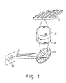
- the optical head device is for use in combination with an optical source 2l and an optical detector assembly 22 placed adjacent to the optical source 2l in general and is for recroding optical information on an optical recording medium 23 and/or reproducing the optical information from the optical recording medium 23.
- the optical head device has a main optical axis and a reference line which is orthogonal to the main optical axis and defines a reference plane in cooperation with the main optical axis.
- the optical source 2l is usually a semiconductor laser or laser diode and is for generating a laser beam along the main optical axis.
- the optical recording medium 23 may be an optical disk, a digital audio disk, or a video disk and has a recording or disk surface on which a plurality of tracks are defined for optical information and which is disposed relative to the optical head device as will shortly be described.
- the optical source 2l and the optical detector assembly 22 are located at positions whose distances from the center of the diffraction grating 35 are equal to each other.
- the optical detector assembly 22 is a four-partitioned optical detector assembly which is known in the art and will be described a bit more in detail in the following.
- the optical detector assembly 22 is a photodiode having a light-receiving surface which is divided by at least two orthogonal or parallel partition lines into a plurality of individual optical detectors.
- one of two orthogonal partition lines passes through the optical source 2l and is parallel to the reference line.
- the partition line under consideration will be called a main partition line.
- the other partition line will be named an auxiliary partition line.
- An intersection of the main and the auxiliary partition lines will be termed an assembly center.
- the individual optical detectors will be referred to as first through fourth optical detectors 26, 27, 28, and 29.
- the first and the second optical detectors 26 and 27 are partitioned by a first part of the main partition line and are on one side of the auxiliary partition line that is nearer to the optical source 2l.
- the third and the fourth optical detectors 28 and 29 are partitioned by a second part of the main partition line and are contiguous on the other side of the auxiliary partition line to the second and the first optical detectors 27 and 26, respectively.
- the optical head device comprises an optical system comprising, in turn, a focussing lens 3l which may not be a single lens as depicted but may be a lens system.
- the focussing lens 3l has a lens axis, is perpendicular to the reference plane, and is accompanied by a lens actuator which is described in the elder patent application and is not depicted in Fig. 2.
- the optical recording medium 23 is held to have the recording surface perpendicular to the lens axis.
- the lens axis and the main optical axis are collinear.
- the tracks have tangents parallel to the reference line.
- the focussing lens 3l receives an input or incident beam along the lens axis to produce a converging beam which is focussed on the recording surface as a light spot of a diameter of about l micron.
- the optical head device makes use of a diverging beam which is reflected from the recording surface as a reflected beam along the lens axis. Responsive to the reflected beam, the focussing lens 3l produces an output or exit beam along the lens axis.
- a diffraction grating 35 is used as a beam splitter unit of the optical system and is arranged perpendicular to the lens axis to have a grating center on the lens axis.
- the diffraction grating 35 is divided by at least one partition line into a plurality of grating regions. Different grating patterns of corrugations are given to the respective grating regions. Supplied with the laser beam along the main optical axis, the grating regions cooperatively produce a zeroth-order diffracted beam as the input beam of the focussing lens 3l.
- the grating regions individually produce sidewards diffracted beams to the optical detector assembly 22 along side optical axes, respectively.
- Each sidewards diffracted beam is preferably a first-order diffracted beam.
- the diffraction grating 35 has a single partition line which passes through the grating center parallel to the reference line.
- the grating regions are therefore first and second grating regions 36 and 37 which are depicted below and above the single partition line merely for convenience of the description that follows.
- a first point of the optical detector assembly 22 is selected on the first part of the main partition line of the optical detector assembly 22.
- a second point is selected on the second part of the main partition line. The first and the second points are equidistant from the assembly center.
- the pattern of the first grating region 36 has interference fringes between a spherical wave front diverged from the optical source 2l and a divergent wave which is an astigmatic wave front having a minimum confusion circle on the first point of the optical detector assembly 22.
- the pattern of the second grating region 37 has interference fringes between the spherical wave front diverged from the optical source 2l and a divergent, astigmatic wave front which has a minimum confusion circle on the second point of the optical detector assembly 22.
- Such a diffraction grating is preferably manufactured like a replica by using a master photoresist pattern for which the interference fringes are drawn by an electronic digital computer.
- the diffraction grating 35 may have an effective area of a diameter of about 5 mm and a grating constant of 2 to 4 microns.
- the first grating region 36 produces a first diffracted beam which forms an image of the first grating region 36 on the first part of the main partition line of the optical detector assembly 22.
- the second grating region 37 produces a second diffracted beam and forms an image of the second grating region 37 on the second part of the main partition line.
- the first through the fourth optical detectors 26 to 29 produce first through fourth electric outputs, respectively.
- the optical information is reproduced as an electric signal by a total sum of the first through the fourth electric outputs.
- a focussing error of the converging beam on the recording surface of the optical recording medium 23 is detected by a difference between a first sum of the first and the third electric outputs and a second sum of the second and the fourth electric outputs.
- a tracking error of the light spot relative to each track of the optical recording medium 23 is detected by another difference between a third sum of the first and the second electric outputs and a fourth sum of the third and the fourth electric outputs.
- the diffraction grating 35 is of the type illustrated with reference to Fig. l hereinabove. It should, however, be pointed out that the diffraction grating 35 is divided into a plurality of grating regions in the manner described above. To wit, the grating regions should comprise a birefractive or birefringent sheet ll (Fig. l) in common. The corrugated surface should have different grating patterns of corrugations or ridges and grooves in the respective grating regions.
- a linearly or plane polarized beam should be used as the laser beam. It will be presumed merely for clarity of description that a mass l2 (Fig. l) in each groove of the diffraction grating 35 has a refractive index which is substantially equal to the extraordinary index of the birefractive sheet. In this event, electric vectors of the linearly polarized beam should be perpendicular to electric vectors of the ordinary component in the birefractive sheet and parallel to electric vectors of the extraordinary component. Such a linearly polarized beam is produced from the optical source 2l readily by one skilled in the art.
- a quarter-wave plate 39 is interposed between the diffraction grating 35 and the focussing lens 3l perpendicular to the lens axis and with its optical axis directed to form an angle of 45° with a plane of polarization of the ordinary or the extraordinary component in the birefractive sheet.
- Substantially l00% of the extraordinary component passes through the grating regions of the diffraction grating 35 as the above-mentioned zeroth-order diffracted beam l4 (Fig. l) which has electric vectors parallel to the above-described grating line.
- the zeroth-order diffracted beam passes through the quarter-wave plate 39 to appear as the input beam of the focussing lens 3l.
- the input beam and consequently the converging beam is now a circularly polarized beam having a plane of polarization subjected to rotation in a first direction which depends on nature of the quarter-wave plate 39.
- the reflected or the diverging beam is given a reversed phase relative to the converging beam by reflection at the recording surface of the optical recording medium 23.
- the reflected beam and in consequence the output beam of the focussing lens 3l is therefore another circularly polarized beam having a plane of polarization subjected to rotation in a second direction which is reversed relative to the first direction.
- the output beam appears as another linearly polarized beam whose electric vectors are orthogonal to those of the zeroth-order diffracted beam.
- the output beam is therefore propagated through the diffraction grating 35 as the ordinary component.
- the grating regions of the diffraction grating 35 individually produce the first-order diffracted beams, such as l5 (Fig. l), as the respective sidewards diffracted beams.
- the first-order diffracted beams such as l5 (Fig. l)
- l5 Fig. l
- each grating region have a high diffraction efficiency. After all, it is possible to raise the laser-beam utilization efficiency of the optical head device.
- the mass in each groove of the diffraction grating 35 may have a refractive index which is substantially equal to the ordinary index of the birefractive sheet.
- the linearly polarized beam should have electric vectors parallel to electric vectors of the ordinary component in the birefractive sheet and perpendicular to electric vectors of the extraordinary component.
- the diffraction grating 35 may not necessarily be a transparent grating but a reflection grating provided that the linearly polarized beam enters the diffraction grating 35, is reflected, and is again propagated through the diffraction grating 35 on its way towards the optical recording medium 23 and also on its return from the optical recording medium 23.
- the diffraction grating 35 may therefore be used in various manners which are described in the elder patent application with the optical detector assembly 22 arranged also in various manners.
- the optical head device comprises similar parts which are designated by like reference numerals.
- the diffraction grating 35 is not of the type illustrated with reference to Fig. l but should be a reflection grating having a corrugated surface which has substantially parallel grating corrugations or ridges and grooves in the respective grating regions and on which aluminium or a like reflective material is attached as by evaporation to provide a corrugated reflective surface.
- the quarter-wave plate 39 should have its optical axis in a direction which forms an angle of 45° with the substantially parallel corrugations.
- a linearly polarized beam is again used as the laser beam.
- the linearly polarized beam should, however, become the p-polarized beam on reaching the reflective surface of the reflection grating 35.
- about 80% of the p-polarized beam is reflected as the zeroth-order diffracted beam to reach the quarter-wave plate 39.
- the converging beam becomes a circularly polarized beam which has a plane of polarization subjected to rotation in a first direction.
- the output beam of the focussing lens 3l becomes another circularly polarized beam having a plane of polarization subjected to rotation in a second direction which is a reversed direction of the first direction.
- the quarter-wave plate 39 supplies the reflective surface of the reflection grating 35 with a linearly polarized beam which is the s-polarized beam.
- the reflection grating 35 therefore directs nearly l00% of the s-polarized beam to the optical detector assembly 22 as the first-order diffracted beams.
- the optical head device has a high laser-beam utilization efficiency.
- the reflection grating 35 may comprise an optically isotropic transparent sheet having an even front surface and a corrugated reflective back surface of the type described above.
- the linearly polarized beam should be incident on the corrugated reflective back surface on its way towards the optical recording medium 23 and also on its return from the optical recording medium 23.
- the reflection grating 35 may have the substantially parallel corrugations in the respective grating regions in the manner described in the elder patent application with reference to Figs. 4, l0, l2, l4 to l6, l9, 2l, 25, 27, 29, 30, 32, and 33 thereof.
- the first point of the optical detector assembly 22 is depicted as a point of intersection of the main partition line of the optical detector assembly 22 and the diameter which the image of the first grating region 36 has on the light-receiving surface of the optical detector assembly 22 when the focussing error is zero.
- the second point of the optical detector assembly 22 is depicted as a point of intersection of the main partition line and the diameter which the image of the second grating region 37 has when the focussing error is zero.
- a combination of the diffraction grating 35 and the quarter-wave plate 39 serves as a grating unit having a direction dependency for a linearly polarized beam on a plane which is perpendicular to the lens axis.
- the diffraction grating is an optically anisotropic grating, although the diffraction grating of Fig. l need not be supplied with a linearly polarized beam. It is possible in Fig. l to cover the even exposed surface with a transparent sheet. Even in this case, the "exposed" surface may so be called.
Landscapes
- Physics & Mathematics (AREA)
- Optics & Photonics (AREA)
- General Physics & Mathematics (AREA)
- Diffracting Gratings Or Hologram Optical Elements (AREA)
- Optical Head (AREA)
Applications Claiming Priority (6)
| Application Number | Priority Date | Filing Date | Title |
|---|---|---|---|
| JP170244/86 | 1986-07-18 | ||
| JP61170244A JP2594548B2 (ja) | 1986-07-18 | 1986-07-18 | 偏光ビームスプリツタ |
| JP294695/86 | 1986-12-12 | ||
| JP61294695A JPH0630166B2 (ja) | 1986-12-12 | 1986-12-12 | 光ヘツド装置 |
| JP62007582A JPH07105057B2 (ja) | 1987-01-16 | 1987-01-16 | 光ヘツド装置 |
| JP7582/87 | 1987-01-16 |
Publications (3)
| Publication Number | Publication Date |
|---|---|
| EP0253403A2 true EP0253403A2 (de) | 1988-01-20 |
| EP0253403A3 EP0253403A3 (en) | 1989-11-15 |
| EP0253403B1 EP0253403B1 (de) | 1993-07-14 |
Family
ID=27277667
Family Applications (1)
| Application Number | Title | Priority Date | Filing Date |
|---|---|---|---|
| EP87110372A Expired - Lifetime EP0253403B1 (de) | 1986-07-18 | 1987-07-17 | Doppelbrechendes Beugungsgitter und optischer Kopf, in welchem ein linearpolarisierter Strahl auf dieses Gitter gelenkt wird |
Country Status (3)
| Country | Link |
|---|---|
| US (1) | US4885734A (de) |
| EP (1) | EP0253403B1 (de) |
| DE (1) | DE3786497T2 (de) |
Cited By (5)
| Publication number | Priority date | Publication date | Assignee | Title |
|---|---|---|---|---|
| EP0405444A3 (en) * | 1989-06-26 | 1992-07-29 | Nec Corporation | Optical head |
| EP0390610A3 (de) * | 1989-03-31 | 1992-09-16 | Sharp Kabushiki Kaisha | Optisches Element und dieses enthaltende optische Abtasteinrichtung |
| WO2004109666A1 (en) * | 2003-06-11 | 2004-12-16 | Koninklijke Philips Electronics N.V. | Apparatus for reading/writing an optical storage carrier |
| EP1645899A3 (de) * | 2004-10-06 | 2006-06-28 | Canon Kabushiki Kaisha | Optische Vorrichtung und Bildaufnahmesystem |
| US7113472B2 (en) | 2001-03-28 | 2006-09-26 | Matsushita Electric Industrial Co., Ltd. | Optical head including an active polymer film for switching voltage during recording and reproducing processes |
Families Citing this family (31)
| Publication number | Priority date | Publication date | Assignee | Title |
|---|---|---|---|---|
| US5804814A (en) * | 1994-05-20 | 1998-09-08 | Musha; Toru | Optical pick-up head and integrated type optical unit for use in optical pick-up head |
| US5270996A (en) * | 1986-12-25 | 1993-12-14 | Nec Corporation | Optical head with diffraction grating producing five diffracted detection light beams |
| DE3887657T2 (de) * | 1987-11-30 | 1994-05-11 | Nippon Electric Co | Optischer Kopf. |
| EP0322714B1 (de) * | 1987-12-24 | 1996-09-11 | Kuraray Co., Ltd. | Polarisierendes optisches Element und Einrichtung unter Benutzung desselben |
| US5115423A (en) * | 1988-01-07 | 1992-05-19 | Ricoh Company, Ltd. | Optomagnetic recording/reproducing apparatus |
| US5066138A (en) * | 1988-06-16 | 1991-11-19 | Mitsubishi Denki Kabushiki Kaisha | Optical head apparatus |
| US4983017A (en) * | 1988-08-02 | 1991-01-08 | Sharp Kabushiki Kaisha | Optical head device for reading information stored in a recording medium |
| EP0374841B1 (de) * | 1988-12-20 | 1994-03-09 | Nec Corporation | Optischer Kopf zur optimalen Detektierung eines Fokusfehlers |
| JPH0778904B2 (ja) * | 1989-01-27 | 1995-08-23 | シャープ株式会社 | 光ピックアップ装置 |
| US5021649A (en) * | 1989-03-28 | 1991-06-04 | Canon Kabushiki Kaisha | Relief diffraction grating encoder |
| US5283690A (en) * | 1989-04-04 | 1994-02-01 | Sharp Kabushiki Kaisha | Optical diffraction grating element |
| JP2800364B2 (ja) * | 1990-04-27 | 1998-09-21 | 松下電器産業株式会社 | 光学的ローパスフィルタ |
| JP2894808B2 (ja) * | 1990-07-09 | 1999-05-24 | 旭光学工業株式会社 | 偏光を有する光学系 |
| JP2865223B2 (ja) * | 1990-12-28 | 1999-03-08 | 松下電子工業株式会社 | 光ピックアップ用偏光板および光ピックアップ装置 |
| EP1120779B1 (de) * | 1992-08-07 | 2003-02-26 | Matsushita Electric Industrial Co., Ltd. | Optisches Speichergerät |
| US5615200A (en) * | 1992-09-10 | 1997-03-25 | Kabushiki Kaisha Toshiba | Light beam shaping device to change an anisotropic beam to an isotropic beam for reducing the size of an optical head |
| EP0612068B1 (de) * | 1993-02-16 | 2000-05-03 | Nec Corporation | Optischer Abtasthopf und doppelbrechender Beugungsgitterpolarisator sowie Hologrammpolarisator dafür. |
| US6072607A (en) * | 1993-10-15 | 2000-06-06 | Sanyo Electric Co., Ltd. | Optical pickup device |
| US5621714A (en) * | 1994-02-12 | 1997-04-15 | Olympus Optical Co., Ltd. | Optical pick-up apparatus having hologram and beam splitter with birefringent member and polarizing film |
| KR100373801B1 (ko) * | 1994-07-29 | 2003-05-09 | 산요 덴키 가부시키가이샤 | 반도체레이저장치및이를이용한광픽업장치 |
| DE4431957A1 (de) * | 1994-09-08 | 1995-03-16 | Basf Ag | Verfahren zur katalytischen Gasphasenoxidation von Propen zu Acrolein |
| DE4431949A1 (de) * | 1994-09-08 | 1995-03-16 | Basf Ag | Verfahren zur katalytischen Gasphasenoxidation von Acrolein zu Acrylsäure |
| JP3861270B2 (ja) * | 1996-02-23 | 2006-12-20 | エプソントヨコム株式会社 | 光ピックアップ及びそれに用いる光学素子 |
| US5920663A (en) * | 1997-12-24 | 1999-07-06 | Lucent Technologies Inc. | Optical waveguide router with controlled transmission characteristics |
| JPH11223729A (ja) * | 1998-02-09 | 1999-08-17 | Sankyo Seiki Mfg Co Ltd | 偏光分離素子およびその製造方法 |
| US6510003B2 (en) | 2001-04-18 | 2003-01-21 | Jds Uniphase Inc. | Cylindrical polarization diversity assembly |
| GB0130513D0 (en) * | 2001-12-20 | 2002-02-06 | Univ Southampton | Device for changing the polarization state of reflected transmitted and diffracted light and for achieving frequency and polarization sensitive reflection and |
| DE10324468B4 (de) * | 2003-05-30 | 2006-11-09 | Carl Zeiss Smt Ag | Mikrolithografische Projektionsbelichtungsanlage, Projektionsobjektiv hierfür sowie darin enthaltenes optisches Element |
| US7804043B2 (en) * | 2004-06-15 | 2010-09-28 | Laserfacturing Inc. | Method and apparatus for dicing of thin and ultra thin semiconductor wafer using ultrafast pulse laser |
| US7889993B2 (en) * | 2007-08-17 | 2011-02-15 | Avago Technologies Fiber Ip (Singapore) Pte. Ltd | Optical transceiver module having a front facet reflector and methods for making and using a front facet reflector |
| FR2942047B1 (fr) * | 2009-02-09 | 2011-06-17 | Commissariat Energie Atomique | Structure et procede d'alignement d'une fibre optique et d'un guide d'ondes submicronique |
Family Cites Families (9)
| Publication number | Priority date | Publication date | Assignee | Title |
|---|---|---|---|---|
| NL160138C (nl) * | 1972-05-11 | 1979-09-17 | Philips Nv | Inrichting voor het uitlezen van een vlakke registratie- drager. |
| NL8303932A (nl) * | 1982-11-17 | 1984-06-18 | Pioneer Electronic Corp | Opneeminrichting voor optische plaat. |
| US4733065A (en) * | 1984-06-27 | 1988-03-22 | Canon Kabushiki Kaisha | Optical head device with diffraction grating for separating a light beam incident on an optical recording medium from a light beam reflected therefrom |
| DE3605516A1 (de) * | 1985-02-21 | 1986-09-04 | Canon K.K., Tokio/Tokyo | Optisches funktionselement sowie optische funktionsvorrichtung |
| NL8502835A (nl) * | 1985-10-17 | 1987-05-18 | Philips Nv | Inrichting voor het met optische straling aftasten van een informatievlak. |
| NL8602980A (nl) * | 1985-11-25 | 1987-06-16 | Mitsubishi Electric Corp | Inrichting voor het registreren en weergeven van optische informatie. |
| JPS62145546A (ja) * | 1985-12-20 | 1987-06-29 | Asahi Optical Co Ltd | 光デイスク情報再生装置 |
| EP0241942B1 (de) * | 1986-04-18 | 1992-03-04 | Mitsubishi Denki Kabushiki Kaisha | Optischer Kopf |
| NL8601974A (nl) * | 1986-08-01 | 1988-03-01 | Philips Nv | Inrichting voor het met optische straling aftasten van een stralingsreflekterend informatievlak. |
-
1987
- 1987-07-17 DE DE87110372T patent/DE3786497T2/de not_active Expired - Lifetime
- 1987-07-17 EP EP87110372A patent/EP0253403B1/de not_active Expired - Lifetime
- 1987-07-20 US US07/075,456 patent/US4885734A/en not_active Expired - Lifetime
Cited By (8)
| Publication number | Priority date | Publication date | Assignee | Title |
|---|---|---|---|---|
| EP0390610A3 (de) * | 1989-03-31 | 1992-09-16 | Sharp Kabushiki Kaisha | Optisches Element und dieses enthaltende optische Abtasteinrichtung |
| EP0803868A3 (de) * | 1989-03-31 | 1997-11-12 | Sharp Kabushiki Kaisha | Optischer Bauteil und optisches Wiedergabegerät mit dergleichem |
| EP0405444A3 (en) * | 1989-06-26 | 1992-07-29 | Nec Corporation | Optical head |
| US5493555A (en) * | 1989-06-26 | 1996-02-20 | Nec Corporation | Optical head using birefringent diffraction grating |
| US7113472B2 (en) | 2001-03-28 | 2006-09-26 | Matsushita Electric Industrial Co., Ltd. | Optical head including an active polymer film for switching voltage during recording and reproducing processes |
| WO2004109666A1 (en) * | 2003-06-11 | 2004-12-16 | Koninklijke Philips Electronics N.V. | Apparatus for reading/writing an optical storage carrier |
| EP1645899A3 (de) * | 2004-10-06 | 2006-06-28 | Canon Kabushiki Kaisha | Optische Vorrichtung und Bildaufnahmesystem |
| US7616879B2 (en) | 2004-10-06 | 2009-11-10 | Canon Kabushiki Kaisha | Optical apparatus and image-taking system |
Also Published As
| Publication number | Publication date |
|---|---|
| DE3786497T2 (de) | 1994-02-17 |
| EP0253403B1 (de) | 1993-07-14 |
| EP0253403A3 (en) | 1989-11-15 |
| US4885734A (en) | 1989-12-05 |
| DE3786497D1 (de) | 1993-08-19 |
Similar Documents
| Publication | Publication Date | Title |
|---|---|---|
| US4885734A (en) | Diffraction grating using birefringence and optical head in which a linearly polarized beam is directed to a diffraction grating | |
| US5013107A (en) | Polarization selective holographic optical element | |
| US4497534A (en) | Holographic optical head | |
| EP0059084B1 (de) | Optisches Auslesegerät | |
| US5659531A (en) | Optical head device and birefringent diffraction grating polarizer and polarizing hologram element used therein | |
| EP0803868B1 (de) | Optisches Bauteil und damit versehenes optisches Wiedergabegerät. | |
| EP0285126B1 (de) | Kopf für magnetooptisches Aufzeichnungsmedium | |
| US4789977A (en) | Optical data recording device | |
| US4993789A (en) | Dual wavelength polarization selective holographic optical element | |
| JPH0651112A (ja) | 二重回折格子ビームスプリッタ | |
| US5708644A (en) | Optical head for optical disk drive | |
| US4689481A (en) | Focus error detector and optical head using the same | |
| US4607359A (en) | Optical recording/reproducing apparatus | |
| JPH1139701A (ja) | 光ディスク装置 | |
| US4595261A (en) | Phase retardation element and prism for use in an optical data storage system | |
| US5751682A (en) | Compact size magneto-optical head with a hologram and a beam splitting means | |
| JPH03225636A (ja) | 光ヘッド装置 | |
| JP2710809B2 (ja) | 交差型回折格子およびこれを用いた偏波回転検出装置 | |
| JPH09145922A (ja) | 回折用光学素子およびこれを用いた光ピックアップ装置 | |
| JPH083906B2 (ja) | 光ヘツド装置 | |
| JP2646782B2 (ja) | 光ヘッド装置 | |
| JP2725324B2 (ja) | 光記録媒体用光ヘッド | |
| KR100261085B1 (ko) | 광픽업장치 | |
| JPH03178064A (ja) | 光ヘッド装置 | |
| JPS61230634A (ja) | 光ヘツド |
Legal Events
| Date | Code | Title | Description |
|---|---|---|---|
| PUAI | Public reference made under article 153(3) epc to a published international application that has entered the european phase |
Free format text: ORIGINAL CODE: 0009012 |
|
| 17P | Request for examination filed |
Effective date: 19870717 |
|
| AK | Designated contracting states |
Kind code of ref document: A2 Designated state(s): DE FR GB NL |
|
| PUAL | Search report despatched |
Free format text: ORIGINAL CODE: 0009013 |
|
| RHK1 | Main classification (correction) |
Ipc: G11B 7/09 |
|
| AK | Designated contracting states |
Kind code of ref document: A3 Designated state(s): DE FR GB NL |
|
| 17Q | First examination report despatched |
Effective date: 19910508 |
|
| GRAA | (expected) grant |
Free format text: ORIGINAL CODE: 0009210 |
|
| AK | Designated contracting states |
Kind code of ref document: B1 Designated state(s): DE FR GB NL |
|
| PG25 | Lapsed in a contracting state [announced via postgrant information from national office to epo] |
Ref country code: NL Effective date: 19930714 |
|
| REF | Corresponds to: |
Ref document number: 3786497 Country of ref document: DE Date of ref document: 19930819 |
|
| ET | Fr: translation filed | ||
| NLV1 | Nl: lapsed or annulled due to failure to fulfill the requirements of art. 29p and 29m of the patents act | ||
| PLBE | No opposition filed within time limit |
Free format text: ORIGINAL CODE: 0009261 |
|
| STAA | Information on the status of an ep patent application or granted ep patent |
Free format text: STATUS: NO OPPOSITION FILED WITHIN TIME LIMIT |
|
| 26N | No opposition filed | ||
| REG | Reference to a national code |
Ref country code: GB Ref legal event code: IF02 |
|
| PGFP | Annual fee paid to national office [announced via postgrant information from national office to epo] |
Ref country code: GB Payment date: 20060712 Year of fee payment: 20 |
|
| PGFP | Annual fee paid to national office [announced via postgrant information from national office to epo] |
Ref country code: DE Payment date: 20060713 Year of fee payment: 20 |
|
| PGFP | Annual fee paid to national office [announced via postgrant information from national office to epo] |
Ref country code: FR Payment date: 20060719 Year of fee payment: 20 |
|
| REG | Reference to a national code |
Ref country code: GB Ref legal event code: PE20 |
|
| PG25 | Lapsed in a contracting state [announced via postgrant information from national office to epo] |
Ref country code: GB Free format text: LAPSE BECAUSE OF EXPIRATION OF PROTECTION Effective date: 20070716 |