EP0252434A2 - Composite plate with a layer of natural stone - Google Patents
Composite plate with a layer of natural stone Download PDFInfo
- Publication number
- EP0252434A2 EP0252434A2 EP19870109508 EP87109508A EP0252434A2 EP 0252434 A2 EP0252434 A2 EP 0252434A2 EP 19870109508 EP19870109508 EP 19870109508 EP 87109508 A EP87109508 A EP 87109508A EP 0252434 A2 EP0252434 A2 EP 0252434A2
- Authority
- EP
- European Patent Office
- Prior art keywords
- layer
- natural stone
- coated
- synthetic resin
- reinforcing
- Prior art date
- Legal status (The legal status is an assumption and is not a legal conclusion. Google has not performed a legal analysis and makes no representation as to the accuracy of the status listed.)
- Granted
Links
Images


Classifications
-
- B—PERFORMING OPERATIONS; TRANSPORTING
- B28—WORKING CEMENT, CLAY, OR STONE
- B28D—WORKING STONE OR STONE-LIKE MATERIALS
- B28D1/00—Working stone or stone-like materials, e.g. brick, concrete or glass, not provided for elsewhere; Machines, devices, tools therefor
- B28D1/003—Multipurpose machines; Equipment therefor
-
- B—PERFORMING OPERATIONS; TRANSPORTING
- B32—LAYERED PRODUCTS
- B32B—LAYERED PRODUCTS, i.e. PRODUCTS BUILT-UP OF STRATA OF FLAT OR NON-FLAT, e.g. CELLULAR OR HONEYCOMB, FORM
- B32B9/00—Layered products comprising a layer of a particular substance not covered by groups B32B11/00 - B32B29/00
- B32B9/002—Layered products comprising a layer of a particular substance not covered by groups B32B11/00 - B32B29/00 comprising natural stone or artificial stone
-
- B—PERFORMING OPERATIONS; TRANSPORTING
- B28—WORKING CEMENT, CLAY, OR STONE
- B28D—WORKING STONE OR STONE-LIKE MATERIALS
- B28D1/00—Working stone or stone-like materials, e.g. brick, concrete or glass, not provided for elsewhere; Machines, devices, tools therefor
- B28D1/005—Cutting sheet laminae in planes between faces
-
- B—PERFORMING OPERATIONS; TRANSPORTING
- B28—WORKING CEMENT, CLAY, OR STONE
- B28D—WORKING STONE OR STONE-LIKE MATERIALS
- B28D7/00—Accessories specially adapted for use with machines or devices of the preceding groups
- B28D7/04—Accessories specially adapted for use with machines or devices of the preceding groups for supporting or holding work or conveying or discharging work
-
- B—PERFORMING OPERATIONS; TRANSPORTING
- B32—LAYERED PRODUCTS
- B32B—LAYERED PRODUCTS, i.e. PRODUCTS BUILT-UP OF STRATA OF FLAT OR NON-FLAT, e.g. CELLULAR OR HONEYCOMB, FORM
- B32B27/00—Layered products comprising a layer of synthetic resin
- B32B27/12—Layered products comprising a layer of synthetic resin next to a fibrous or filamentary layer
-
- B—PERFORMING OPERATIONS; TRANSPORTING
- B32—LAYERED PRODUCTS
- B32B—LAYERED PRODUCTS, i.e. PRODUCTS BUILT-UP OF STRATA OF FLAT OR NON-FLAT, e.g. CELLULAR OR HONEYCOMB, FORM
- B32B9/00—Layered products comprising a layer of a particular substance not covered by groups B32B11/00 - B32B29/00
- B32B9/04—Layered products comprising a layer of a particular substance not covered by groups B32B11/00 - B32B29/00 comprising such particular substance as the main or only constituent of a layer, which is next to another layer of the same or of a different material
- B32B9/047—Layered products comprising a layer of a particular substance not covered by groups B32B11/00 - B32B29/00 comprising such particular substance as the main or only constituent of a layer, which is next to another layer of the same or of a different material made of fibres or filaments
-
- E—FIXED CONSTRUCTIONS
- E04—BUILDING
- E04C—STRUCTURAL ELEMENTS; BUILDING MATERIALS
- E04C2/00—Building elements of relatively thin form for the construction of parts of buildings, e.g. sheet materials, slabs, or panels
- E04C2/02—Building elements of relatively thin form for the construction of parts of buildings, e.g. sheet materials, slabs, or panels characterised by specified materials
- E04C2/04—Building elements of relatively thin form for the construction of parts of buildings, e.g. sheet materials, slabs, or panels characterised by specified materials of concrete or other stone-like material; of asbestos cement; of cement and other mineral fibres
- E04C2/06—Building elements of relatively thin form for the construction of parts of buildings, e.g. sheet materials, slabs, or panels characterised by specified materials of concrete or other stone-like material; of asbestos cement; of cement and other mineral fibres reinforced
-
- E—FIXED CONSTRUCTIONS
- E04—BUILDING
- E04C—STRUCTURAL ELEMENTS; BUILDING MATERIALS
- E04C2/00—Building elements of relatively thin form for the construction of parts of buildings, e.g. sheet materials, slabs, or panels
- E04C2/02—Building elements of relatively thin form for the construction of parts of buildings, e.g. sheet materials, slabs, or panels characterised by specified materials
- E04C2/26—Building elements of relatively thin form for the construction of parts of buildings, e.g. sheet materials, slabs, or panels characterised by specified materials composed of materials covered by two or more of groups E04C2/04, E04C2/08, E04C2/10 or of materials covered by one of these groups with a material not specified in one of the groups
-
- E—FIXED CONSTRUCTIONS
- E04—BUILDING
- E04F—FINISHING WORK ON BUILDINGS, e.g. STAIRS, FLOORS
- E04F13/00—Coverings or linings, e.g. for walls or ceilings
- E04F13/07—Coverings or linings, e.g. for walls or ceilings composed of covering or lining elements; Sub-structures therefor; Fastening means therefor
- E04F13/08—Coverings or linings, e.g. for walls or ceilings composed of covering or lining elements; Sub-structures therefor; Fastening means therefor composed of a plurality of similar covering or lining elements
- E04F13/14—Coverings or linings, e.g. for walls or ceilings composed of covering or lining elements; Sub-structures therefor; Fastening means therefor composed of a plurality of similar covering or lining elements stone or stone-like materials, e.g. ceramics concrete; of glass or with an outer layer of stone or stone-like materials or glass
- E04F13/144—Coverings or linings, e.g. for walls or ceilings composed of covering or lining elements; Sub-structures therefor; Fastening means therefor composed of a plurality of similar covering or lining elements stone or stone-like materials, e.g. ceramics concrete; of glass or with an outer layer of stone or stone-like materials or glass with an outer layer of marble or other natural stone
-
- E—FIXED CONSTRUCTIONS
- E04—BUILDING
- E04F—FINISHING WORK ON BUILDINGS, e.g. STAIRS, FLOORS
- E04F15/00—Flooring
- E04F15/02—Flooring or floor layers composed of a number of similar elements
-
- E—FIXED CONSTRUCTIONS
- E04—BUILDING
- E04F—FINISHING WORK ON BUILDINGS, e.g. STAIRS, FLOORS
- E04F15/00—Flooring
- E04F15/02—Flooring or floor layers composed of a number of similar elements
- E04F15/08—Flooring or floor layers composed of a number of similar elements only of stone or stone-like material, e.g. ceramics, concrete; of glass or with a top layer of stone or stone-like material, e.g. ceramics, concrete or glass
-
- B—PERFORMING OPERATIONS; TRANSPORTING
- B32—LAYERED PRODUCTS
- B32B—LAYERED PRODUCTS, i.e. PRODUCTS BUILT-UP OF STRATA OF FLAT OR NON-FLAT, e.g. CELLULAR OR HONEYCOMB, FORM
- B32B2262/00—Composition or structural features of fibres which form a fibrous or filamentary layer or are present as additives
- B32B2262/10—Inorganic fibres
- B32B2262/101—Glass fibres
-
- B—PERFORMING OPERATIONS; TRANSPORTING
- B32—LAYERED PRODUCTS
- B32B—LAYERED PRODUCTS, i.e. PRODUCTS BUILT-UP OF STRATA OF FLAT OR NON-FLAT, e.g. CELLULAR OR HONEYCOMB, FORM
- B32B2305/00—Condition, form or state of the layers or laminate
- B32B2305/08—Reinforcements
-
- Y—GENERAL TAGGING OF NEW TECHNOLOGICAL DEVELOPMENTS; GENERAL TAGGING OF CROSS-SECTIONAL TECHNOLOGIES SPANNING OVER SEVERAL SECTIONS OF THE IPC; TECHNICAL SUBJECTS COVERED BY FORMER USPC CROSS-REFERENCE ART COLLECTIONS [XRACs] AND DIGESTS
- Y10—TECHNICAL SUBJECTS COVERED BY FORMER USPC
- Y10T—TECHNICAL SUBJECTS COVERED BY FORMER US CLASSIFICATION
- Y10T428/00—Stock material or miscellaneous articles
- Y10T428/24—Structurally defined web or sheet [e.g., overall dimension, etc.]
- Y10T428/24355—Continuous and nonuniform or irregular surface on layer or component [e.g., roofing, etc.]
- Y10T428/24372—Particulate matter
- Y10T428/24421—Silicon containing
- Y10T428/2443—Sand, clay, or crushed rock or slate
-
- Y—GENERAL TAGGING OF NEW TECHNOLOGICAL DEVELOPMENTS; GENERAL TAGGING OF CROSS-SECTIONAL TECHNOLOGIES SPANNING OVER SEVERAL SECTIONS OF THE IPC; TECHNICAL SUBJECTS COVERED BY FORMER USPC CROSS-REFERENCE ART COLLECTIONS [XRACs] AND DIGESTS
- Y10—TECHNICAL SUBJECTS COVERED BY FORMER USPC
- Y10T—TECHNICAL SUBJECTS COVERED BY FORMER US CLASSIFICATION
- Y10T428/00—Stock material or miscellaneous articles
- Y10T428/31504—Composite [nonstructural laminate]
- Y10T428/31511—Of epoxy ether
- Y10T428/31515—As intermediate layer
- Y10T428/31518—Next to glass or quartz
-
- Y—GENERAL TAGGING OF NEW TECHNOLOGICAL DEVELOPMENTS; GENERAL TAGGING OF CROSS-SECTIONAL TECHNOLOGIES SPANNING OVER SEVERAL SECTIONS OF THE IPC; TECHNICAL SUBJECTS COVERED BY FORMER USPC CROSS-REFERENCE ART COLLECTIONS [XRACs] AND DIGESTS
- Y10—TECHNICAL SUBJECTS COVERED BY FORMER USPC
- Y10T—TECHNICAL SUBJECTS COVERED BY FORMER US CLASSIFICATION
- Y10T442/00—Fabric [woven, knitted, or nonwoven textile or cloth, etc.]
- Y10T442/10—Scrim [e.g., open net or mesh, gauze, loose or open weave or knit, etc.]
- Y10T442/102—Woven scrim
- Y10T442/133—Inorganic fiber-containing scrim
- Y10T442/143—Including a nonwoven fabric which is not a scrim
Definitions
- the invention relates to a composite panel with a natural stone layer, which has a visible surface and a back, and with a reinforcing layer, as well as a method and an apparatus for their production.
- Such a composite plate designed as a base plate or cladding plate, can be found, for example, in DE-A-34 15 779. It shows a natural stone slab with a rear reinforcement layer, which consists of bands running in the direction of pull, embedded in synthetic resin, in particular made of carbon fibers, and is intended for laying in a mortar or gravel bed.
- the tensile reinforcement is of course able to absorb positive load moments from a concave deflection of the natural stone slab, but it cannot counteract negative load moments.
- glass fiber reinforced plastic layers for tensile and pressure reinforcement as intermediate layers of several chipboards for stair treads, pedestal panels etc. are known from DE-A-23 64 321.
- a plastic layer is foamed on both sides of the slabs cut from the full blocks in a mold, which reinforces the natural stone, so that a subsequent separation without damage is possible. This process can be repeated if necessary, so that natural stone layers with 1 to 2 mm can be achieved.
- the halving cuts must be made precisely due to the decreasing layer thickness. It is clear that with layer thicknesses of 1 to 2 mm to be produced, even slight deviations in the cutting plane destroy the natural stone layer. Such natural stone slabs must therefore be cut individually, so that the multiple saws customary for stone slab production can hardly be used. Since minimal thickness errors can add up when several plastic sheets foamed on both sides are lined up in series, it is quite conceivable that, for example with a package of ten sheets, the halving cuts from the fourth sheet lie next to the natural stone layer.
- two-layer composite panels with a 5 mm thick natural stone layer are also present.
- this is provided with an additional connecting web (for example made of concrete), so that the first cut can also be made over the entire height of the natural stone block, and spacers are inserted into the kerfs before the saw blades are removed not to change the distances until filling out.
- this method is relatively time-consuming and labor-intensive, since the later visible surface of each composite panel is produced in the first cut, cast again for the execution of the second cut and finally has to be exposed again.
- the invention has now set itself the task of creating a composite panel of the type mentioned that can be sawn with the smallest possible thickness and used as a mere, statically non-load-bearing, large cladding panel.
- Another object of the invention is to develop a method in which the separating cuts of a package of natural stone slabs coated on both sides actually halve them.
- a composite panel according to the invention contains a reinforcing layer, one with the Back of the natural stone layer connected, tensile forces from concave bending of the visible surface absorbing fiber layer and at least one compressive force from convex bending of the visible surface layer made of synthetic resin, which is arranged on the side of the tensile reinforcing fiber layer facing away from the natural stone layer.
- a composite body according to the invention thus not only has the known tensile reinforcement, but also a pressure reinforcement, so that the vibration forces acting perpendicular to the cutting plane in both directions are absorbed without damaging the marble slab.
- a very thin layer of marble can be achieved, which is preferably less than 3 mm after the saw surface has been ground.
- the pressure-reinforcing layer made of synthetic resin is provided with reinforcements which consist of a close-meshed glass fiber fabric facing the tensile reinforcing fiber layer and of a subsequent glass fiber mat.
- reinforcements consist of a close-meshed glass fiber fabric facing the tensile reinforcing fiber layer and of a subsequent glass fiber mat.
- a method according to the invention for producing such composite panels provides that the natural stone panels are coated on both sides with the reinforcing layer, and that several of the coated natural stone panels are arranged next to one another with equal distances between their central planes and cut at the same time.
- a known multiple saw frame is advantageously used, ie a natural stone block is cut in the conventional manner sawed several natural stone slabs at the same time.
- the natural stone slabs are then dried and, after drying, coated on both sides with the reinforcement layer.
- glass fibers embedded in synthetic resin are preferably used, which form a tensile and compressive reinforcement if a first layer in the form of a glass fiber mat, then a second layer in the form of a close-knit glass fiber fabric and finally a third layer of glass fiber mat are applied to the natural stone.
- the thickness of this multilayer coating is approximately two millimeters.
- the natural stone slabs coated in this way are now bundled together and placed on the block wagon of a multiple saw frame so that the saw blades lie in the middle planes of the natural stone slabs.
- the alignment is preferably carried out by means of spacers and the cavities formed between them are at least partially filled with a filling material.
- the second cuts are made, which create the visible surfaces of the composite panels.
- Any filler with inorganic or organic binders are particularly suitable as filler material, a significant advantage over the above-mentioned process according to DE-A-2833874 is that the coated side comes into contact with the filler material, so that the filler material is removed from the natural stone visible surface is eliminated. Since the bond between the filler material and the reinforcement layer is normally low, this is released when the composite panels are removed from the package.
- a preferred device for producing such composite panels which comprises a multiple saw frame and a block wagon, provides that the block wagon has a tiltable platform, that a spacer is provided in each of the coated natural stone slabs, preferably four rows running perpendicular to the tilt axis, and that a fixed one on the tipping axis and an adjustable side support is arranged opposite.
- the platform of the block car is tilted upwards, so that the natural stone plates lie against the spacers on one side.
- These are preferably adjustable along rails.
- the adjustable side support is pushed onto the last plate of the package and the platform is folded back into the horizontal.
- the halving cuts are made in the desired positions, since thickness tolerances from the first cut and the coating cannot add up.
- the individually adjustable spacers make it possible to individually adjust the center planes of the cutting planes even for very thin panels.
- a block 16 made of natural stone, in particular marble, is placed in a multiple saw frame in natural stone slabs 12 saws that can not fall below a certain thickness, about 18 to 20 mm.
- the block 16 is arranged in a block carriage 21 and fixed between two side supports 27, 28, one of which has an adjustable pressing device 30.
- the individual natural stone slabs 12 (FIG. 1) are dried in a drying room at approximately 100 ° C. and provided with a reinforcing layer 13 on the cut surfaces.
- the reinforcement layer 13 is composed of a fiber layer 2 with reinforcement, which is connected to the natural stone layer 1 by means of an epoxy resin layer 11 as an adhesive bridge, and a subsequent layer 3, which in turn is multilayered.
- the fiber layer 2 has an epoxy resin layer 4 as an embedding compound for a glass fiber mat 8 serving as a reinforcement, which preferably has a weight of 350 g / m 2.
- a final sand coating 10 with a grain size between 0.1 and 0.25 mm can also be provided for laying in tile adhesive. The sand coating 10 is not provided if the composite panel is used as clothing for smooth surfaces, such as doors, furniture, etc.
- the multilayer layer 3 consists of an epoxy resin layer 5 adjoining the fiber layer 2 as an embedding compound for a glass fiber fabric 6, a further epoxy resin layer 7 as an embedding compound for a second fiber layer in the form of a glass fiber mat 8 with 225 g / m 2 and a final epoxy resin layer 9 which mentioned the one Sand coating 10 can wear.
- the glass fiber fabric 6 and the glass fiber mat 8 form reinforcements 4 of the layer 3 serving as pressure reinforcement of the natural stone layer 1 made of synthetic resin.
- Reinforcing layer 3 made of synthetic resin-coated natural stone slab 12 can be sawn without any problems using conventional stone saws or stone circular saws by grinding the later visible surface to a thickness of 2 to 3 mm, whereby the tensile and compressive reinforcement absorbs vibrational forces and the risk of breakage is practically excluded. Since the natural stone layer 1 in the composite panel comprises approximately half its thickness, a total of cladding panels of approximately 4 to 5 mm in thickness are formed, which have an area of up to 2 m2 and have a remarkable elasticity.
- spacers 23 are provided on the block wagon 21 at least on the platform 25 and on the top, which are preferably adjustable along rails 24 (FIG. 7). As can be seen from FIG. 5, the platform 25 of the block wagon 21 can be swiveled up about the axis 26, the adjustable side support 28 being folded down about the axis 29.
- the coated natural stone slabs 12 can be packaged in the receiving space, the first being placed on the inclined side support 27 and all others on the spacers 23, so that each natural stone slab 12 is in the desired position in which (FIG.
- a saw blade 22 of the multiple saw frame lies in the central plane of the natural stone slab 12.
- the natural stone slabs 12 are preferably fixed to the platform 27 by means of an adhesive, for example a stone base plate. A summation of thickness errors is therefore not possible.
- the adjustable side support 28 is pivoted into the working position and the platform 25 is folded down.
- the pressure device 30 of the side support 28 is placed on the outermost natural stone slab 12, so that it is pressed against its spacers 23.
- the cavities 15 between the natural stone slabs 12 are at least partially filled with a filling material 14, for example mortar, so that a set package is prepared for the second cut after hardening.
- the filler material 14 is preferably free on the plate shape side of an outflow gap for the water penetrating during cutting.
- the filler material shown in FIG. 7 extends over the two vertical edge strips; this is sufficient to determine the natural stone slabs.
- the reinforcement layer 13 forming the tensile and compressive reinforcement absorbs the forces generated by the division of the natural stone slab 12.
- the second cut divides each coated natural stone slab 12 into a composite slab with a very thin natural stone layer 1 and the reinforcing layer 13.
Abstract
Eine Verbundplatte besteht aus einer Natursteinschicht (1) und einer Verstärkungsschicht (13). Diese weist eine in Kunstharz eingebettete Faserschicht (2) und mindestens eine Lage (3) aus Kunstharz auf. Die Faserschicht (2) dient als Zugbewehrung und die Lage (3) aus Kunstharz als Druckbewehrung für die Natursteinschicht (1), sodaß die Verbundplatte sowohl positive als auch negative Biegemomente aufnehmen kann. Die Kunstharzlage (3) ist bevorzugt verstärkt, beispielsweise mit einem zur zugfesten Faserschicht (2) weisenden, engmaschigen Glasfasergewebe (6) und einer anschließenden Glasfasermatte (8) versehen. Zur Herstellung der Verbundplatten werden dicker geschnittene Natursteinplatten beidseitig mit der Verstärkungsschicht (13) beschichtet. Mehrere beschichtete Natursteinplatten werden dann mit gleichen Abständen zwischen ihren Mittelebenen nebeneinander angeordnet und gleichzeitig geschnitten.A composite panel consists of a natural stone layer (1) and a reinforcement layer (13). This has a fiber layer (2) embedded in synthetic resin and at least one layer (3) made of synthetic resin. The fiber layer (2) serves as tensile reinforcement and the layer (3) made of synthetic resin as pressure reinforcement for the natural stone layer (1), so that the composite panel can absorb both positive and negative bending moments. The synthetic resin layer (3) is preferably reinforced, for example provided with a narrow-mesh glass fiber fabric (6) pointing towards the tensile fiber layer (2) and a subsequent glass fiber mat (8). To produce the composite panels, thicker cut natural stone panels are coated on both sides with the reinforcing layer (13). Several coated natural stone slabs are then arranged next to each other with equal distances between their central planes and cut at the same time.
Description
Die Erfindung betrifft eine Verbundplatte mit einer Natursteinschicht, die eine Sichtfläche und eine Rückseite aufweist, und mit einer Verstärkungsschicht, sowie ein Verfahren und eine Vorrichtung zu deren Herstellung.The invention relates to a composite panel with a natural stone layer, which has a visible surface and a back, and with a reinforcing layer, as well as a method and an apparatus for their production.
Eine derartige, als Bodenplatte bzw. auch Verkleidungsplatte ausgebildete Verbundplatte ist beispielsweise der DE-A-34 15 779 zu entnehmen. Sie zeigt eine Natursteinplatte mit einer rückseitigen Zugbewehrungsschicht, die aus in Zugrichtung verlaufenden, in Kunstharz eingebetteten Bändern, insbesondere aus Kohlefasern besteht, und zur Verlegung in einem Mörtel- oder Kiesbett bestimmt ist. Die Zugbewehrung ist natürlich in der Lage, positive Belastungsmomente aus einer konkaven Durchbiegung der Natursteinplatte aufzunehmen, negativen Belastungsmomenten kann sie jedoch nicht entgegenwirken. Da bei der Einbettung in die Unterlage eine mittige Anhäufung des Bettmaterials nicht ausschließbar ist, wird der Bruch der Natursteinplatte durch negative Belastungsmomente dadurch verhindert, daß in einem Randauflagestreifen freilassenden Mittelfeld eine elastisch zusammendrückbare Verdrängungsschicht etwa aus Weichschaumstoff aufgebracht wird, sodaß das Plattenauflager ausschließlich im Umfangsbereich gegeben ist.Such a composite plate, designed as a base plate or cladding plate, can be found, for example, in DE-A-34 15 779. It shows a natural stone slab with a rear reinforcement layer, which consists of bands running in the direction of pull, embedded in synthetic resin, in particular made of carbon fibers, and is intended for laying in a mortar or gravel bed. The tensile reinforcement is of course able to absorb positive load moments from a concave deflection of the natural stone slab, but it cannot counteract negative load moments. Since a central accumulation of the bed material cannot be ruled out during embedding in the underlay, the breakage of the natural stone slab due to negative load moments is prevented by applying an elastically compressible displacement layer, for example made of soft foam, in a central field that leaves open the support strip, so that the slab support is only provided in the peripheral area is.
Andererseits sind glasfaserverstärkte Kunststoffschichten für Zug- und Druckbewehrung als Zwischenlagen von mehreren Holzspanplatten für Treppenstufen, Podestplatten usw. aus der DE-A-23 64 321 bekannt.On the other hand, glass fiber reinforced plastic layers for tensile and pressure reinforcement as intermediate layers of several chipboards for stair treads, pedestal panels etc. are known from DE-A-23 64 321.
Bei der Herstellung von Natursteinplatten lassen sich ohne besondere Hilfsmittel nur minimale Plattenstärken von etwa 18 bis 20 mm erzielen, wobei die Platten aus vollen Blöcken mittels Sägegattern geschnitten werden. Platten mit geringerer Dicke brechen durch die Vibrationen der Säge, durch die sowohl Zug- als auch Druckkräfte auftreten. Die Natursteinplatten weisen weiters auch ein relativ hohes Gewicht auf, sodaß deren behutsame Handhabung erschwert ist, wodurch die Bruchgefahr nochmals erhöht ist. Es hat sich in der Folge gezeigt, daß leichte Steinplatten dann hergestellt werden können, wenn der Naturstein nur eine Schicht einer Verbundplatte ist, wobei eine zweite Schicht aus einem leichten Trägermaterial besteht. Ein derartiges Verfahren ist beispielsweise aus der DE-A-21 29 057 bekannt geworden. Dort wird an die aus den vollen Blöcken geschnittenen Platten in einer Form beidseitig eine Kunststoffschicht angeschäumt, die den Naturstein verstärkt, sodaß eine nachfolgende Trennung ohne Beschädigung möglich wird. Dieses Verfahren läßt sich gegebenenfalls wiederholen, sodaß Natursteinschichten mit 1 bis 2 mm erzielbar sind.In the production of natural stone slabs, only minimal slab thicknesses of around 18 to 20 mm can be achieved without special aids, the slabs being cut from solid blocks using saws. Slabs of reduced thickness break through the vibrations of the saw, through which both tensile and compressive forces occur. The natural stone slabs also have a relatively high weight, so that their careful handling is difficult, which increases the risk of breakage. It has subsequently been shown that light stone slabs can be produced when the natural stone is only one layer of a composite slab, a second layer consisting of a light carrier material. Such a method has become known, for example, from DE-A-21 29 057. There, a plastic layer is foamed on both sides of the slabs cut from the full blocks in a mold, which reinforces the natural stone, so that a subsequent separation without damage is possible. This process can be repeated if necessary, so that natural stone layers with 1 to 2 mm can be achieved.
Die Halbierungsschnitte müssen infolge abnehmender Schichtdicke präzise angesetzt werden. Es ist klar, daß bei herzustellenden Schichtdicken von 1 bis 2 mm auch geringfügige Abweichungen der Schnittebene bereits die Natursteinschicht zerstören. Derartige Natursteinplatten müssen daher einzeln geschnitten werden, sodaß die für die Steinplattenherstellung üblichen Mehrfachsägegatter kaum einsetzbar sind. Da sich bei der Aneinanderreihung mehrerer beidseitig geschäumter Kunststoffplatten minimale Dickenfehler addieren können, ist es durchaus denkbar, daß, etwa bei einem Paket von zehn Platten, ab der vierten Platte die Halbierungsschnitte neben der Natursteinschicht liegen.The halving cuts must be made precisely due to the decreasing layer thickness. It is clear that with layer thicknesses of 1 to 2 mm to be produced, even slight deviations in the cutting plane destroy the natural stone layer. Such natural stone slabs must therefore be cut individually, so that the multiple saws customary for stone slab production can hardly be used. Since minimal thickness errors can add up when several plastic sheets foamed on both sides are lined up in series, it is quite conceivable that, for example with a package of ten sheets, the halving cuts from the fourth sheet lie next to the natural stone layer.
Ein weiteres Verfahren beschreibt die DE-A-28 33 874. Hier tritt das Problem der exakten Positionierung der Schnittebenen nicht auf. In einem Mehrfachsägegatter wird ein Natursteinblock in größeren Abständen eingeschnitten, wobei an der Auflageseite ein Verbindungssteg belassen wird. Die entstandenen Spalten werden mit expandierendem Kunstharz oder anderem Material zumindest teilweise gefüllt. Der Block wird dann verschoben und ein zweiter Schnitt über die gesamte Höhe vorgenommen. So entsteht eine Verbundplatte mit zwei äußeren Natursteinschichten, die über den Steg einseitig verbunden sind und der mittleren Füllschicht. Nun wird jede Außenseite mit einer verstärkenden Schicht, etwa einer Glasfaser-Kunstharz-Schicht überzogen, der Verbindungssteg abgetrennt und die fünfschichtige Verbundplatte entlang der mittleren Kunststoffschicht geteilt. Nach Reinigung, Schleifen und Polieren der freigelegten Natursteinsichtfläche liegen ebenfalls zweischichtige Verbundplatten mit einer beispielsweise 5 mm dicken Natursteinschicht vor. In einer Variante wird vor dem ersten Schneiden des Natursteinblocks dieser mit einem zusätzlichen Verbindungssteg (etwa aus Beton) versehen, sodaß auch der Erstschnitt über die gesamte Höhe des Natursteinblockes geführt werden kann,und vor dem Entfernen der Sägeblätter werden in die Schnittfugen Abstandhalter eingesetzt, um die Distanzen bis zum Ausfüllen nicht zu verändern. Insgesamt ist dieses Verfahren relativ zeit- und arbeitsaufwendig, da die spätere Sichtfläche jeder Verbundplatte im ersten Schnitt erzeugt, für die Ausführung des zweiten Schnittes wieder vergossen und schließlich wieder freigelegt werden muß.Another method is described in DE-A-28 33 874. The problem of the exact positioning of the cutting planes does not arise here. In a multiple saw frame, a natural stone block is cut at greater intervals, leaving a connecting bar on the support side becomes. The resulting gaps are at least partially filled with expanding synthetic resin or other material. The block is then moved and a second cut is made over the entire height. This creates a composite panel with two outer layers of natural stone that are connected on one side via the web and the middle filler layer. Now each outside is covered with a reinforcing layer, such as a glass fiber synthetic resin layer, the connecting web is cut off and the five-layer composite panel is divided along the middle plastic layer. After cleaning, grinding and polishing the exposed natural stone visible surface, two-layer composite panels with a 5 mm thick natural stone layer are also present. In a variant, before the first cut of the natural stone block, this is provided with an additional connecting web (for example made of concrete), so that the first cut can also be made over the entire height of the natural stone block, and spacers are inserted into the kerfs before the saw blades are removed not to change the distances until filling out. Overall, this method is relatively time-consuming and labor-intensive, since the later visible surface of each composite panel is produced in the first cut, cast again for the execution of the second cut and finally has to be exposed again.
Die Erfindung hat es sich nun zur Aufgabe gestellt, eine Verbundplatte der eingangs genannten Art zu schaffen, die mit möglichst geringer Dicke sägbar und als bloße, statisch nicht tragende, großflächige Verkleidungsplatte einsetzbar ist. Eine weitere Aufgabe der Erfindung liegt darin, ein Verfahren zur entwickeln, bei dem die Trennschnitte eines Paketes von beidseitig beschichteten Natursteinplatten diese auch tatsächlich halbieren.The invention has now set itself the task of creating a composite panel of the type mentioned that can be sawn with the smallest possible thickness and used as a mere, statically non-load-bearing, large cladding panel. Another object of the invention is to develop a method in which the separating cuts of a package of natural stone slabs coated on both sides actually halve them.
Eine erfindungsgemße Verbundplatte enthält zur Lösung der Aufgabe eine Verstärkungsschicht, die eine mit der Rückseite der Natursteinschicht verbundene, Zugkräfte aus konkaven Verbiegungen der Sichtfläche aufnehmende Faserschicht und mindestens eine Druckkräfte aus konvexen Verbiegungen der Sichtfläche aufnehmende Lage aus Kunstharz aufweist, die an der der Natursteinschicht abgewandten Seite der zugbewehrenden Faserschicht angeordnet ist.To achieve the object, a composite panel according to the invention contains a reinforcing layer, one with the Back of the natural stone layer connected, tensile forces from concave bending of the visible surface absorbing fiber layer and at least one compressive force from convex bending of the visible surface layer made of synthetic resin, which is arranged on the side of the tensile reinforcing fiber layer facing away from the natural stone layer.
Ein erfindungsgemäßer Verbundkörper besitzt somit nicht nur die bekannte Zugbewehrung, sondern auch eine Druckbewehrung, sodaß die senkrecht zur Schnittebene in beiden Richtungen wirkenden Vibrationskräfte ohne Beschädigung der Marmorplatte aufgenommen werden. Dabei kann eine sehr dünne Marmorschicht erzielt werden, die nach dem erforderlichen Schliff der Sägefläche vorzugsweise unter 3 mm liegt.A composite body according to the invention thus not only has the known tensile reinforcement, but also a pressure reinforcement, so that the vibration forces acting perpendicular to the cutting plane in both directions are absorbed without damaging the marble slab. A very thin layer of marble can be achieved, which is preferably less than 3 mm after the saw surface has been ground.
In einer bevorzugten Ausführung ist vorgesehen, daß die druckbewehrende Lage aus Kunstharz mit Verstärkungen versehen ist, die aus einem zur zugbewehrenden Faserschicht weisenden, engmaschigen Glasfasergewebe und aus einer anschließenden Glasfasermatte bestehen. Durch die Verstärkung der Druckbewehrung kann auch die Gesamtdicke der Kunststoffschicht sehr gering gehalten werden. Die zugbewehrende Faserschicht besteht vorzugsweise ebenfalls aus einer Glasfasermatte.In a preferred embodiment it is provided that the pressure-reinforcing layer made of synthetic resin is provided with reinforcements which consist of a close-meshed glass fiber fabric facing the tensile reinforcing fiber layer and of a subsequent glass fiber mat. By strengthening the pressure reinforcement, the total thickness of the plastic layer can also be kept very small. The tensile reinforcing fiber layer preferably also consists of a glass fiber mat.
Ein erfindungsgemäßes Verfahren zur Herstellung derartiger Verbundplatten sieht vor, daß die Natursteinplatten beidseitig mit der Verstärkungsschicht beschichtet werden, und daß mehrere der beschichteten Natursteinplatten mit gleichen Abständen zwischen ihren Mittelebenen nebeneinander angeordnet und gleichzeitig geschnitten werden.A method according to the invention for producing such composite panels provides that the natural stone panels are coated on both sides with the reinforcing layer, and that several of the coated natural stone panels are arranged next to one another with equal distances between their central planes and cut at the same time.
Für den Zuschnitt der dickeren Natursteinplatte wird vorteilhaft ein bekanntes Mehrfachsägegatter eingesetzt, d.h. ein Natursteinblock wird in herkömmlicher Weise in mehrere Natursteinplatten gleichzeitig zersägt. Die Natursteinplatten werden anschließend getrocknet und nach dem Trocknen beidseitig mit der Verstärkungsschicht überzogen. Dafür werden bevorzugt in Kunstharz eingebettete Glasfasern verwendet, die eine Zug- und Druckbewehrung bilden, wenn an den Naturstein eine erste Lage in Form einer Glasfasermatte, anschließend eine zweite Lage in Form eines engmaschigen Glasfasergewebes und schließlich als dritte Lage eine Glasfasermatte aufgebracht werden. Die Dicke dieser mehrlagigen Beschichtung beträgt etwa zwei Millimeter. Die so beschichteten Natursteinplatten werden nun paketeweise zusammengefaßt und auf dem Blockwagen eines Mehrfachsägegatters so aufgestellt, daß die Sägeblätter in den Mittelebenen der Natursteinplatten liegen. Die Ausrichtung erfolgt vorzugsweise mittels Abstandhaltern und die zwischen diesen gebildeten Hohlräume werden mit einem Füllmaterial zumindest teilweise gefüllt. Anschließend erfolgen die zweiten Schnitte, die die Sichtflächen der Verbundplatten erzeugen. Als Füllmaterial eignen sich vor allem beliebige Mörtel mit anorganischen oder organischen Bindemitteln, wobei ein wesentlicher Vorteil gegenüber dem oben erwähnten Verfahren nach der DE-A-2833874 darin liegt, daß die beschichtete Seite mit dem Füllmaterial in Berührung kommt, sodaß eine Entfernung des Füllmaterials von der Natursteinsichtfläche entfällt. Da die Bindung zwischen Füllmaterial und der Verstärkungsschicht im Normalfall gering ist, löst sich dieses bei der Entnahme der Verbundplatten aus dem Paket.For the cutting of the thicker natural stone slab, a known multiple saw frame is advantageously used, ie a natural stone block is cut in the conventional manner sawed several natural stone slabs at the same time. The natural stone slabs are then dried and, after drying, coated on both sides with the reinforcement layer. For this purpose, glass fibers embedded in synthetic resin are preferably used, which form a tensile and compressive reinforcement if a first layer in the form of a glass fiber mat, then a second layer in the form of a close-knit glass fiber fabric and finally a third layer of glass fiber mat are applied to the natural stone. The thickness of this multilayer coating is approximately two millimeters. The natural stone slabs coated in this way are now bundled together and placed on the block wagon of a multiple saw frame so that the saw blades lie in the middle planes of the natural stone slabs. The alignment is preferably carried out by means of spacers and the cavities formed between them are at least partially filled with a filling material. Then the second cuts are made, which create the visible surfaces of the composite panels. Any filler with inorganic or organic binders are particularly suitable as filler material, a significant advantage over the above-mentioned process according to DE-A-2833874 is that the coated side comes into contact with the filler material, so that the filler material is removed from the natural stone visible surface is eliminated. Since the bond between the filler material and the reinforcement layer is normally low, this is released when the composite panels are removed from the package.
Eine bevorzugte Vorrichtung zur Herstellung derartiger Verbundplatten,die ein Mehrfachsägegatter und einen Blockwagen umfaßt, sieht vor, daß der Blockwagen eine kippbare Plattform aufweist, daß in, vorzugsweise vier, senkrecht zur Kippachse verlaufenden Reihen pro aufzustellender beschichteter Natursteinplatte jeweils ein Abstandhalter vorgesehen ist, und daß kippachsenseitig eine feststehende und gegenüberliegend eine verstellbare Seitenstütze angeordnet ist.A preferred device for producing such composite panels, which comprises a multiple saw frame and a block wagon, provides that the block wagon has a tiltable platform, that a spacer is provided in each of the coated natural stone slabs, preferably four rows running perpendicular to the tilt axis, and that a fixed one on the tipping axis and an adjustable side support is arranged opposite.
Für die Beschickung des Blockwagens mit den beschichteten Natursteinplatten wird die Plattform des Blockwagens schräg hochgekippt, sodaß sich die Natursteinplatten an die Abstandhalter einseitig anlegen. Diese sind vorzugsweise entlang von Schienen verstellbar. Die verstellbare Seitenstütze wird an die letzte Platte des Paketes angeschoben und die Plattform in die Horizontale zurückgeklappt. Nach dem Ausfüllen der Hohlräume erfolgen die Halbierungsschnitte in den gewünschten Positionen, da sich Dickentoleranzen aus dem Erstschnitt und der Beschichtung nicht summieren können. Die einzeln verstellbaren Abstandhalter ermögliches es auch bei sehr dünnen Platten deren Mittelebenen einzeln auf die Schnittebenen einzustellen.For the loading of the block car with the coated natural stone slabs, the platform of the block car is tilted upwards, so that the natural stone plates lie against the spacers on one side. These are preferably adjustable along rails. The adjustable side support is pushed onto the last plate of the package and the platform is folded back into the horizontal. After filling in the cavities, the halving cuts are made in the desired positions, since thickness tolerances from the first cut and the coating cannot add up. The individually adjustable spacers make it possible to individually adjust the center planes of the cutting planes even for very thin panels.
Nachstehend wird nun die Erfindung anhand der Figuren der beiliegenden Zeichnungen näher beschrieben, ohne darauf beschränkt zu sein.The invention will now be described in more detail below with reference to the figures in the accompanying drawings, without being limited thereto.
Es zeigen:
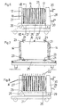
- Fig. 1 eine doppelseitig beschichtete Natursteinplatte vor dem Trennschnitt,
- Fig. 2 eine Verbundplatte nach der Erfindung,
- Fig. 3 den Schichtaufbau im Detail,
- Fig. 4 einen Natursteinblock vor dem Erstschnitt,
- Fig. 5 und 6 die Bildung eines Paketes von beabstandeten Natursteinplatten,
- Fig. 7 einen Schnitt nach der Linie VII-VII in Fig. 6, und
- Fig. 8 das Plattenpaket vor dem Zweitschnitt.
- 1 is a double-sided coated natural stone slab before the cut,
- 2 a composite panel according to the invention,
- 3 shows the layer structure in detail,
- 4 a natural stone block before the first cut,
- 5 and 6, the formation of a package of spaced natural stone slabs,
- Fig. 7 is a section along the line VII-VII in Fig. 6, and
- Fig. 8, the plate pack before the second cut.
Ein Block 16 aus Naturstein, insbesondere Marmor, wird in einem Mehrfachsägegatter in Natursteinplatten 12 zersägt, die eine bestimmte Dicke, etwa 18 bis 20 mm, nicht unterschreiten können. Für die Durchführung des Erstschnittes (Fig. 4 ) ist der Block 16 in einem Blockwagen 21 angeordnet und zwischen zwei Seitenstützen 27,28 fixiert, von denen eine eine verstellbare Anpreßeinrichtung 30 aufweist. Die einzelnen Natursteinplatten 12 (Fig. 1) werden in einem Trockenraum bei etwa 100°C getrocknet und an den Schnittflächen mit einer Verstärkungsschicht 13 versehen. Die Verstärkungsschicht 13 setzt sich gemäß Fig. 3 aus einer zugbewehrenden Faserschicht 2, die mittels einer Epoxidharzschicht 11 als Haftbrücke mit der Natursteinschicht 1 verbunden ist, und einer anschließenden Lage 3 zusammen, die ihrerseits wieder mehrschichtig ist. Die Faserschicht 2 weist eine Epoxidharzschicht 4 als Einbettungsmasse für eine als Zugbewehrung dienende Glasfasermatte 8 auf, die bevorzugt ein Gewicht von 350 g/m² besitzt. Für eine Verlegung in Fliesenkleber kann noch eine abschließende Sandbeschichtung 10 mit einer Korngröße zwischen 0,1 und 0,25 mm vorgesehen sei. Die Sandbeschichtung 10 ist dann nicht vorgesehen, wenn die Verbundplatte als Bekleidung glatter Oberflächen, wie Türen, Möbel etc.,Verwendung findet.A
Die mehrschichtige Lage 3 besteht aus einer an die Faserschicht 2 anschließenden Epoxidharzschicht 5 als Einbettungsmasse für ein Glasfasergewebe 6, einer weiteren Epoxidharzschicht 7 als Einbettungsmasse für eine zweite Faserschicht in Form einer Glasfasermatte 8 mit 225 g/m² und einer abschließenden Epoxidharzschicht 9, die die erwähnte Sandbeschichtung 10 tragen kann. Das Glasfasergewebe 6 und die Glasfasermatte 8 bilden dabei Verstärkungen 4 der als Druckbewehrung der Natursteinschicht 1 dienenden Lage 3 aus Kunstharz.The
Zurückkommend auf Fig. 1 kann nun eine beidseitig mit einer zugbewehrenden Faserschicht 2 und einer druck bewehrenden Lage 3 aus Kunstharz beschichtete Natursteinplatte 12 problemlos mittels herkömmlicher Steinsägegatter oder Steinkreissägen zersägt werden Die ursprüngliche Dicke von 18 mm wird unter Berücksichtigung einer Sägeschnittbreite von 5 bis 7 mm auf eine Dicke der Natursteinschicht 1 (Fig. 2) von 5 bis 6 mm verringert und durch Beschleifen der späteren Sichtfläche auf eine Dicke von 2 bis 3 mm reduziert, wobei die Zug- und Druckbewehrung vibrationsbedingte Kräfte aufnimmt, und die Bruchgefahr praktisch ausgeschlossen ist. Da die Natursteinschicht 1 in der Verbundplatte etwa dessen halbe Dicke umfaßt, entstehen insgesamt Verkleidungsplatten von etwa 4 bis 5 mm Dicke, die eine Fläche bis zu 2 m² aufweisen und eine bemerkenswerte Elastizität besitzen.Returning to FIG. 1, one can now have a
Da sowohl der Erstschnitt als auch die Verstärkungsbeschichtung gewisse Dickentoleranzen bedingen, besteht bei der Paketierung der beschichteten Platten für den Zweitschnitt die Gefahr einer zu großen Verschiebung der Schnittebenen. Um dies auszuschließen, sind am Blockwagen 21 zumindest an der Plattform 25 und an der Oberseite Abstandhalter 23 vorgesehen, die vorzugsweise entlang von Schienen 24 verstellbar sind (Fig. 7). Wie aus Fig. 5 ersichtlich, ist die Plattform 25 des Blockwagens 21 um die Achse 26 hochschwenkbar, wobei die verstellbare Seitenstütze 28 um die Achse 29 abgeklappt ist. In dem Aufnahmeraum können die beschichteten Natursteinplatten 12 paketiert werden, wobei die erste an die geneigte Seitenstütze 27 und alle weiteren an die Abstandhalter 23 angelegt werden, sodaß jede Natursteinplatte 12 sich in der gewünschten Position befindet, in der (Fig. 8) ein Sägeblatt 22 des Mehrfachsägegatters in der Mittelebene der Natursteinplatte 12 liegt. Die Natursteinplatten 12 werden dabei vorzugsweise mittels eines Klebers an der Plattform 27, etwa einer Unterlagsplatte aus Stein, fixiert. Eine Summierung von Dickenfehlern ist somit nicht möglich. Nach der Paketierung wird die verstellbare Seitenstütze 28 in die Arbeitslage verschwenkt und die Plattform 25 niedergeklappt. An die äußerste Natursteinplatte 12 wird die Anpreßeinrichtung 30 der Seitenstütze 28 angelegt, sodaß diese an ihre Abstandhalter 23 angepreßt wird.Since both the first cut and the reinforcement coating require certain thickness tolerances, there is a risk of the cutting planes being shifted too much when the coated panels are packaged for the second cut. To rule this out, spacers 23 are provided on the
Die Hohlräume 15 zwischen den Natursteinplatten 12 werden mit einem Füllmaterial 14, beispielsweise Mörtel, zumindest teilweise gefüllt, sodaß nach dem Erhärten ein lagefixiertes Paket für den Zweitschnitt vorbereitet ist. Bevorzugt wird das Füllmaterial 14 plattenformseitig einen Ausflußspalt für das beim Schneiden eindringende Wasser freilassen. Das in Fig. 7 gezeigte Füllmaterial erstreckt sich über die beiden vertikalen Randstreifen; dies genügt zur Festlegung der Natursteinplatten. Die die Zug- und Druckbewehrung bildende Verstärkungsschicht 13 nimmt die durch die Teilung der Natursteinplatte 12 entstehenden Kräfte auf. Der Zweitschnitt teilt jede beschichtete Natursteinplatte 12 in eine Verbundplatte mit sehr dünner Natursteinschicht 1 und der Verstärkungsschicht 13.The
Claims (10)
Applications Claiming Priority (6)
| Application Number | Priority Date | Filing Date | Title |
|---|---|---|---|
| AT1841/86 | 1986-07-08 | ||
| AT184186 | 1986-07-08 | ||
| AT933/87 | 1986-08-26 | ||
| AT243/87 | 1987-02-06 | ||
| AT24387A AT390225B (en) | 1987-02-06 | 1987-02-06 | Method and device for producing composite slabs |
| AT93387A AT388013B (en) | 1986-07-08 | 1987-04-14 | Composite body |
Publications (3)
| Publication Number | Publication Date |
|---|---|
| EP0252434A2 true EP0252434A2 (en) | 1988-01-13 |
| EP0252434A3 EP0252434A3 (en) | 1989-01-25 |
| EP0252434B1 EP0252434B1 (en) | 1992-03-25 |
Family
ID=27146044
Family Applications (1)
| Application Number | Title | Priority Date | Filing Date |
|---|---|---|---|
| EP19870109508 Expired - Lifetime EP0252434B1 (en) | 1986-07-08 | 1987-07-02 | Composite plate with a layer of natural stone |
Country Status (5)
| Country | Link |
|---|---|
| US (2) | US4855177A (en) |
| EP (1) | EP0252434B1 (en) |
| CA (1) | CA1281879C (en) |
| DE (1) | DE3777703D1 (en) |
| ES (1) | ES2031473T3 (en) |
Cited By (18)
| Publication number | Priority date | Publication date | Assignee | Title |
|---|---|---|---|---|
| DE3801603A1 (en) * | 1988-01-21 | 1989-07-27 | Guenter Weidenschlager | Process for producing composites comprising a layer of natural stone and a reinforcing layer |
| DE8807781U1 (en) * | 1988-06-15 | 1989-08-03 | Vilcsek, Rainer, 6250 Limburg, De | |
| EP0344619A1 (en) * | 1988-06-01 | 1989-12-06 | TECNOMAIERA S.r.l. | A method for the production of reinforced panels from a block of building material, such as stone |
| DE3940102A1 (en) * | 1988-12-07 | 1990-06-13 | Wolfgang Lehner | Light-wt. panel with natural stone surface - made of specified lamination of veneer and carrier layers |
| DE3916331A1 (en) * | 1989-03-29 | 1990-10-04 | H P Chemie Pelzer Res & Dev | Composite tile - with baseplate of regenerated plastic and thin faceplate of natural material |
| US5226402A (en) * | 1989-11-30 | 1993-07-13 | Tecnomaiera S.R.L. | Method for the production of composite panels based on ornamental stone or an equivalent material |
| EP0596681A1 (en) * | 1992-11-02 | 1994-05-11 | Gencorp Inc. | Masonry-bondable membranes, their manufacture and use |
| EP0698483A3 (en) * | 1994-08-25 | 1996-06-19 | Marcello Toncelli | Process for the production of reinforced slabs of stone material |
| DE19547123A1 (en) * | 1994-12-20 | 1996-08-08 | Naturstein Wigand Gmbh & Co Kg | Composite plate, esp. kitchen work top |
| EP0786332A1 (en) * | 1996-01-29 | 1997-07-30 | TONCELLI, Marcello | Process for the production of reinforced slabs of stone material and reinforced slabs obtained. |
| WO1997030567A1 (en) * | 1996-02-16 | 1997-08-21 | Kolja Kuse | Induction cooking device with stone surface for use as a work surface top |
| WO1997033736A1 (en) * | 1996-03-11 | 1997-09-18 | Vilcsek Rainer | Method of producing thin plates from natural or synthetic stone |
| US5860255A (en) * | 1996-05-09 | 1999-01-19 | Gencorp Inc. | Masonry-bondable, water-resistant flexible membrane |
| WO2001007248A1 (en) * | 1999-07-28 | 2001-02-01 | Uralita De Productos Y Servicios, S.A. | Compound tile having a natural stone visible face, and fabrication process |
| DE19920492A1 (en) * | 1999-05-05 | 2001-03-22 | Rochus Jogerst Gmbh | Process for producing a shaped body with a thin natural stone layer that is visible on the surface |
| WO2005035906A1 (en) | 2003-09-18 | 2005-04-21 | Peter Kellner | Heatable floor element having a surface layer |
| DE102008044803A1 (en) | 2008-08-28 | 2010-03-04 | Kellner, Peter | A flooring system |
| AT517350A4 (en) * | 2015-09-14 | 2017-01-15 | Klh Massivholz Gesmbh | Process for the production of wood-concrete composite elements |
Families Citing this family (23)
| Publication number | Priority date | Publication date | Assignee | Title |
|---|---|---|---|---|
| US5314554A (en) * | 1988-04-05 | 1994-05-24 | Owens Charles R | Method for producing a laminated tile product |
| US4973014A (en) * | 1988-06-27 | 1990-11-27 | Creative Systems Engineering, Inc. | Conduit bracket lock system |
| US5004512A (en) * | 1989-08-21 | 1991-04-02 | Frank Fodera | Method of making a stone veneer panel |
| WO1991015345A1 (en) * | 1990-04-04 | 1991-10-17 | Peterson Carl W | Waterproof and corrosion resistant concrete articles and process of preparing the same |
| US5078815A (en) * | 1990-06-11 | 1992-01-07 | Othon Robert S | Method of making a decorative transparent laminate of stone and glass |
| US5585161A (en) * | 1992-01-22 | 1996-12-17 | Difloe; Donna M. | Bond site reinforcement in thermal bonded highloft non-wovens |
| CA2122214A1 (en) * | 1993-04-29 | 1994-10-30 | John F. Thomas | Reinforced concrete tiles and methods of making same |
| IT1313119B1 (en) * | 1999-08-26 | 2002-06-17 | Quarella Spa | MANUFACTURE IN MULTILAYER COMPOSITE SLABS OF STONE GRANULES ERELATIVE MANUFACTURING PROCEDURE |
| DE10034632B4 (en) * | 2000-07-17 | 2005-09-01 | Karl Krüger GmbH & Co. KG | Plate-shaped component using a natural stone plate |
| ES2189611B1 (en) * | 2000-12-15 | 2004-10-16 | Ricardo Abad Gonzalez | PROCEDURE OF MANUFACTURE OF A PART FOR COATING OF INTERIOR AND / OR OUTSIDE SURFACES OF BUILDINGS. |
| DE10201905B4 (en) * | 2001-03-26 | 2004-07-08 | Peter Kellner | Floor made of individual elements |
| US8046968B2 (en) * | 2001-03-26 | 2011-11-01 | Peter Kellner | Floor made from individual elements |
| ITVI20020075A1 (en) * | 2002-04-29 | 2003-10-29 | Carlo Bastianello | PROCEDURE FOR THE PRODUCTION OF STRIPS OR OTHER SIMILAR PRODUCTS OBTAINED FROM BLOCKS OF STONE, EVEN CRACKED |
| MXPA05006205A (en) * | 2002-12-10 | 2006-01-27 | Smartslate Inc | Rock laminate. |
| CN100436733C (en) * | 2006-06-23 | 2008-11-26 | 上海新四合木业有限公司 | Strengthening type three-layered wood compound floor board and mfg. method thereof |
| ES2374673B1 (en) * | 2010-08-09 | 2012-12-27 | Bemarsa-Benicantil Mármoles, S.A. | PROCEDURE OF MANUFACTURE OF MULTILAMINAR PLATE OF NATURAL STONE OF REDUCED THICKNESS. |
| AU2010246330A1 (en) * | 2010-11-01 | 2012-05-17 | Finish Systems International, Llc | Stone-wood composite base engineered flooring |
| CN102152402A (en) * | 2011-01-25 | 2011-08-17 | 黄桂芳 | Method for processing ultrathin stone slab and production process for composite plate of ultrathin stone slab |
| US20120301713A1 (en) * | 2011-05-25 | 2012-11-29 | Xiang Yang Hong | Transparent Composite Slate |
| JP2016153577A (en) * | 2015-02-20 | 2016-08-25 | 凸版印刷株式会社 | Backside material for siding board, siding board, and method of manufacturing backside material for siding board |
| PL229192B1 (en) * | 2015-11-27 | 2018-06-29 | Rog Stanislaw Przed Pentar | Dish-type flap wheel |
| WO2019183691A1 (en) * | 2018-03-28 | 2019-10-03 | Gustavo Costa Napolitano | Process of manufacturing slabs |
| ES2803825A1 (en) * | 2019-07-24 | 2021-01-29 | Continental Stone And Marble Slu | PROCEDURE FOR THE MANUFACTURE OF MARBLE SHEETS OR SIMILAR FROM MARBLE TABLES OF ROUGH BLOCKS (Machine-translation by Google Translate, not legally binding) |
Citations (4)
| Publication number | Priority date | Publication date | Assignee | Title |
|---|---|---|---|---|
| DE2129057A1 (en) | 1971-06-11 | 1972-12-28 | Alhäuser, Gerhard, 6341 Hirzenhain | Process for the production of building panels from thin-walled natural stone, as well as building panel manufactured according to the process |
| DE2364321A1 (en) | 1973-12-22 | 1975-06-26 | Kenngott Kg | SMALLER COMPONENTS, IN PARTICULAR STAIR TREAD, PLATFORM PLATE, CEILING PLATE, WALL ELEMENTS OD. DGL. |
| DE2833874A1 (en) | 1977-08-03 | 1979-02-22 | Giuseppe Marocco | METHOD OF MANUFACTURING STONE SLABS |
| DE3415779A1 (en) | 1984-04-27 | 1985-10-31 | Andreas Dipl.-Ing. 8023 Pullach Volkwein | Ashlar slab |
Family Cites Families (11)
| Publication number | Priority date | Publication date | Assignee | Title |
|---|---|---|---|---|
| US1007540A (en) * | 1910-10-25 | 1911-10-31 | M W Cross | Stoneworking-table. |
| US3089478A (en) * | 1961-04-17 | 1963-05-14 | Jefferson F Jones | Miter table for use with masonry saw |
| US3993822A (en) * | 1970-02-25 | 1976-11-23 | Gebr. Knauf Westdeutsche Gipswerke | Multi-layer plasterboard |
| DE2156181C2 (en) * | 1971-11-12 | 1973-12-13 | Kenngott Kg, 7100 Heilbronn | Process for the production of thin cladding panels with natural stones for furniture, walls and floors |
| CA1056178A (en) * | 1976-01-19 | 1979-06-12 | Morris Schupack | Reinforced panel structures and methods for producing them |
| AT352966B (en) * | 1977-12-22 | 1979-10-25 | Rada Oswald | BUILDING PLATE AND METHOD OF MANUFACTURING IT |
| AU531527B2 (en) * | 1979-05-30 | 1983-08-25 | Bpb Industries Ltd. | Cementitious building board |
| DE2929963A1 (en) * | 1979-07-24 | 1981-02-12 | Hill Plattenwerk Hermann | Light cladding panel of splittable material - is made by cementing support layer onto block, then removing with split layer |
| CH663052A5 (en) * | 1983-04-21 | 1987-11-13 | Amrotex Ag | MOLDED PIECE MADE OF HYDRAULICALLY SET MATERIAL. |
| US4617219A (en) * | 1984-12-24 | 1986-10-14 | Morris Schupack | Three dimensionally reinforced fabric concrete |
| JPS61188138A (en) * | 1985-02-15 | 1986-08-21 | 株式会社ブリヂストン | Corrosion-protective structure |
-
1987
- 1987-07-02 ES ES87109508T patent/ES2031473T3/en not_active Expired - Lifetime
- 1987-07-02 DE DE8787109508T patent/DE3777703D1/en not_active Expired - Fee Related
- 1987-07-02 EP EP19870109508 patent/EP0252434B1/en not_active Expired - Lifetime
- 1987-07-07 CA CA 541406 patent/CA1281879C/en not_active Expired - Lifetime
- 1987-07-08 US US07/070,949 patent/US4855177A/en not_active Expired - Lifetime
-
1989
- 1989-05-12 US US07/351,197 patent/US4911138A/en not_active Expired - Fee Related
Patent Citations (4)
| Publication number | Priority date | Publication date | Assignee | Title |
|---|---|---|---|---|
| DE2129057A1 (en) | 1971-06-11 | 1972-12-28 | Alhäuser, Gerhard, 6341 Hirzenhain | Process for the production of building panels from thin-walled natural stone, as well as building panel manufactured according to the process |
| DE2364321A1 (en) | 1973-12-22 | 1975-06-26 | Kenngott Kg | SMALLER COMPONENTS, IN PARTICULAR STAIR TREAD, PLATFORM PLATE, CEILING PLATE, WALL ELEMENTS OD. DGL. |
| DE2833874A1 (en) | 1977-08-03 | 1979-02-22 | Giuseppe Marocco | METHOD OF MANUFACTURING STONE SLABS |
| DE3415779A1 (en) | 1984-04-27 | 1985-10-31 | Andreas Dipl.-Ing. 8023 Pullach Volkwein | Ashlar slab |
Cited By (29)
| Publication number | Priority date | Publication date | Assignee | Title |
|---|---|---|---|---|
| DE3801603A1 (en) * | 1988-01-21 | 1989-07-27 | Guenter Weidenschlager | Process for producing composites comprising a layer of natural stone and a reinforcing layer |
| EP0344619A1 (en) * | 1988-06-01 | 1989-12-06 | TECNOMAIERA S.r.l. | A method for the production of reinforced panels from a block of building material, such as stone |
| WO1989011958A1 (en) * | 1988-06-01 | 1989-12-14 | Tecnomaiera S.R.L. | A method for the production of reinforced panels from a block of building material, such as stone |
| AU612863B2 (en) * | 1988-06-01 | 1991-07-18 | Tecnomaiera S.R.L. | Reinforced panels |
| US5131378A (en) * | 1988-06-01 | 1992-07-21 | Tecnomaiera S.R.L. | Method for the production of reinforced panels from a block of building material, such as stone |
| DE8807781U1 (en) * | 1988-06-15 | 1989-08-03 | Vilcsek, Rainer, 6250 Limburg, De | |
| DE3940102A1 (en) * | 1988-12-07 | 1990-06-13 | Wolfgang Lehner | Light-wt. panel with natural stone surface - made of specified lamination of veneer and carrier layers |
| AT396232B (en) * | 1988-12-07 | 1993-07-26 | Wolfgang Lehner | METHOD FOR COATING FURNITURE, WALLS AND FLOORS WITH THIN NATURAL OR ARTIFICIAL LAYER LAYERS |
| DE3916331A1 (en) * | 1989-03-29 | 1990-10-04 | H P Chemie Pelzer Res & Dev | Composite tile - with baseplate of regenerated plastic and thin faceplate of natural material |
| US5226402A (en) * | 1989-11-30 | 1993-07-13 | Tecnomaiera S.R.L. | Method for the production of composite panels based on ornamental stone or an equivalent material |
| US5595625A (en) * | 1992-11-02 | 1997-01-21 | Gencorp Inc. | Method of manufacturing an anti-fracture, water-resistant, masonry-bondable membrane |
| US5481838A (en) * | 1992-11-02 | 1996-01-09 | Gencorp Inc. | Anti-fracture, water-resistant, masonry-bondable membrane |
| EP0596681A1 (en) * | 1992-11-02 | 1994-05-11 | Gencorp Inc. | Masonry-bondable membranes, their manufacture and use |
| EP0698483A3 (en) * | 1994-08-25 | 1996-06-19 | Marcello Toncelli | Process for the production of reinforced slabs of stone material |
| US5670007A (en) * | 1994-08-25 | 1997-09-23 | Toncelli; Marcello | Process for the production of reinforced slabs of stone material |
| DE19547123A1 (en) * | 1994-12-20 | 1996-08-08 | Naturstein Wigand Gmbh & Co Kg | Composite plate, esp. kitchen work top |
| EP0786332A1 (en) * | 1996-01-29 | 1997-07-30 | TONCELLI, Marcello | Process for the production of reinforced slabs of stone material and reinforced slabs obtained. |
| WO1997030567A1 (en) * | 1996-02-16 | 1997-08-21 | Kolja Kuse | Induction cooking device with stone surface for use as a work surface top |
| WO1997033736A1 (en) * | 1996-03-11 | 1997-09-18 | Vilcsek Rainer | Method of producing thin plates from natural or synthetic stone |
| US5860255A (en) * | 1996-05-09 | 1999-01-19 | Gencorp Inc. | Masonry-bondable, water-resistant flexible membrane |
| DE19920492A1 (en) * | 1999-05-05 | 2001-03-22 | Rochus Jogerst Gmbh | Process for producing a shaped body with a thin natural stone layer that is visible on the surface |
| WO2001007248A1 (en) * | 1999-07-28 | 2001-02-01 | Uralita De Productos Y Servicios, S.A. | Compound tile having a natural stone visible face, and fabrication process |
| AU766320B2 (en) * | 1999-07-28 | 2003-10-16 | Uralita De Productos Y Servicios, S.A. | Compound tile having a natural stone visible face, and fabrication process |
| US6660384B1 (en) | 1999-07-28 | 2003-12-09 | Uralita De Productos Y Servicios, S.A. | Compound tile having a natural stone visible face and fabrication process |
| CN1301855C (en) * | 1999-07-28 | 2007-02-28 | 乌拉利塔产品服务有限公司 | Compound tile having having a natural stone visible face and fabrication process |
| WO2005035906A1 (en) | 2003-09-18 | 2005-04-21 | Peter Kellner | Heatable floor element having a surface layer |
| DE102008044803A1 (en) | 2008-08-28 | 2010-03-04 | Kellner, Peter | A flooring system |
| AT517350A4 (en) * | 2015-09-14 | 2017-01-15 | Klh Massivholz Gesmbh | Process for the production of wood-concrete composite elements |
| AT517350B1 (en) * | 2015-09-14 | 2017-01-15 | Klh Massivholz Gesmbh | Process for the production of wood-concrete composite elements |
Also Published As
| Publication number | Publication date |
|---|---|
| CA1281879C (en) | 1991-03-26 |
| EP0252434A3 (en) | 1989-01-25 |
| US4911138A (en) | 1990-03-27 |
| US4855177A (en) | 1989-08-08 |
| ES2031473T3 (en) | 1992-12-16 |
| DE3777703D1 (en) | 1992-04-30 |
| EP0252434B1 (en) | 1992-03-25 |
Similar Documents
| Publication | Publication Date | Title |
|---|---|---|
| EP0252434B1 (en) | Composite plate with a layer of natural stone | |
| DE2833874C2 (en) | ||
| DE3223246A1 (en) | Multi-layer insulating slab and process for manufacture thereof | |
| EP1704290A1 (en) | Tile to be used in a laying system, especially for producing a floor covering and method for producing the same | |
| DE4133416C2 (en) | Process for the production of moldings, in particular insulation boards | |
| DE2156181C2 (en) | Process for the production of thin cladding panels with natural stones for furniture, walls and floors | |
| EP0303139A1 (en) | Façade element with a stone plate and method of manufacturing such an element | |
| DE2503123A1 (en) | Composite plate prodn. with core and foamed binder medium - has binder medium foamed by chemical or thermal type gas prodn. material | |
| DE3042078A1 (en) | CEMENT PANEL, AND METHOD AND DEVICE FOR THE PRODUCTION THEREOF | |
| DE19609468C1 (en) | Process for making thin slabs from natural or artificial stone | |
| EP0426015B1 (en) | Multiply wood products such as beams, planks and glued boards and process for their manufacture | |
| EP0939063B1 (en) | Method and apparatus for coating and/or impregnating mineral wool products | |
| DE10119552A1 (en) | Large work, wall or floor plate with a natural stone cover comprises a carrier layer with two stabilizing layers in the form of a mineral fiber mat embedded in resin, and an intermediate layer of hard foam | |
| DE4143387A1 (en) | Mfg.mineral fibre building insulating slabs - assembles fibre strips with different fibre patterns and machines edges to form tongue-and-groove joints | |
| EP1378197A1 (en) | Basement for a shower tray | |
| DE10318072A1 (en) | Compound plate, for a kitchen working surface, has an upper stone plate bonded to a lower carrier plate by an intermediate hard foam layer to reduce the plate weight | |
| EP0056660A2 (en) | Use of rigid foam panels for thermal insulation of building fronts | |
| DE2512777A1 (en) | Fire wall elements and fire doors - using asbestos cement panels with inner layers of flexible glass fibre and mica core panels | |
| DE4316099A1 (en) | Mineral-wool insulating plate - has front and rear surfaces machined to form parallel horizontal grooves which are evenly spaced | |
| DE3801603A1 (en) | Process for producing composites comprising a layer of natural stone and a reinforcing layer | |
| AT390225B (en) | Method and device for producing composite slabs | |
| DE4135581A1 (en) | Reinforced construction plate - has spaced grids embedded in coating mass covering base plate, grids are kept apart by distance holders of swellable material | |
| DE102005003801B4 (en) | Insulating element and thermal insulation composite system | |
| AT396344B (en) | PANEL SHAPED COMPOSITE ELEMENT | |
| DE60124115T2 (en) | GLASS ELEMENT CONNECTION |
Legal Events
| Date | Code | Title | Description |
|---|---|---|---|
| PUAI | Public reference made under article 153(3) epc to a published international application that has entered the european phase |
Free format text: ORIGINAL CODE: 0009012 |
|
| AK | Designated contracting states |
Kind code of ref document: A2 Designated state(s): AT BE CH DE ES FR GB GR IT LI LU NL SE |
|
| PUAL | Search report despatched |
Free format text: ORIGINAL CODE: 0009013 |
|
| AK | Designated contracting states |
Kind code of ref document: A3 Designated state(s): AT BE CH DE ES FR GB GR IT LI LU NL SE |
|
| 17P | Request for examination filed |
Effective date: 19890526 |
|
| 17Q | First examination report despatched |
Effective date: 19910417 |
|
| GRAA | (expected) grant |
Free format text: ORIGINAL CODE: 0009210 |
|
| AK | Designated contracting states |
Kind code of ref document: B1 Designated state(s): AT BE CH DE ES FR GB GR IT LI LU NL SE |
|
| PG25 | Lapsed in a contracting state [announced via postgrant information from national office to epo] |
Ref country code: SE Effective date: 19920325 Ref country code: NL Effective date: 19920325 Ref country code: GR Free format text: LAPSE BECAUSE OF FAILURE TO SUBMIT A TRANSLATION OF THE DESCRIPTION OR TO PAY THE FEE WITHIN THE PRESCRIBED TIME-LIMIT Effective date: 19920325 Ref country code: BE Effective date: 19920325 |
|
| REF | Corresponds to: |
Ref document number: 74063 Country of ref document: AT Date of ref document: 19920415 Kind code of ref document: T |
|
| REF | Corresponds to: |
Ref document number: 3777703 Country of ref document: DE Date of ref document: 19920430 |
|
| ITF | It: translation for a ep patent filed |
Owner name: ING. ANTON AUSSERER |
|
| GBT | Gb: translation of ep patent filed (gb section 77(6)(a)/1977) | ||
| PG25 | Lapsed in a contracting state [announced via postgrant information from national office to epo] |
Ref country code: LU Free format text: LAPSE BECAUSE OF NON-PAYMENT OF DUE FEES Effective date: 19920731 |
|
| ET | Fr: translation filed | ||
| NLV1 | Nl: lapsed or annulled due to failure to fulfill the requirements of art. 29p and 29m of the patents act | ||
| REG | Reference to a national code |
Ref country code: ES Ref legal event code: FG2A Ref document number: 2031473 Country of ref document: ES Kind code of ref document: T3 |
|
| PLBI | Opposition filed |
Free format text: ORIGINAL CODE: 0009260 |
|
| 26 | Opposition filed |
Opponent name: NORTH WEST MINING SERVICES GMBH Effective date: 19921223 |
|
| PGFP | Annual fee paid to national office [announced via postgrant information from national office to epo] |
Ref country code: GB Payment date: 19940701 Year of fee payment: 8 |
|
| PLBN | Opposition rejected |
Free format text: ORIGINAL CODE: 0009273 |
|
| STAA | Information on the status of an ep patent application or granted ep patent |
Free format text: STATUS: OPPOSITION REJECTED |
|
| 27O | Opposition rejected |
Effective date: 19940520 |
|
| PG25 | Lapsed in a contracting state [announced via postgrant information from national office to epo] |
Ref country code: GB Effective date: 19950702 |
|
| GBPC | Gb: european patent ceased through non-payment of renewal fee |
Effective date: 19950702 |
|
| PGFP | Annual fee paid to national office [announced via postgrant information from national office to epo] |
Ref country code: FR Payment date: 20040720 Year of fee payment: 18 |
|
| PGFP | Annual fee paid to national office [announced via postgrant information from national office to epo] |
Ref country code: AT Payment date: 20040722 Year of fee payment: 18 |
|
| PGFP | Annual fee paid to national office [announced via postgrant information from national office to epo] |
Ref country code: CH Payment date: 20040723 Year of fee payment: 18 |
|
| PGFP | Annual fee paid to national office [announced via postgrant information from national office to epo] |
Ref country code: ES Payment date: 20040726 Year of fee payment: 18 |
|
| PGFP | Annual fee paid to national office [announced via postgrant information from national office to epo] |
Ref country code: DE Payment date: 20040920 Year of fee payment: 18 |
|
| PG25 | Lapsed in a contracting state [announced via postgrant information from national office to epo] |
Ref country code: IT Free format text: LAPSE BECAUSE OF NON-PAYMENT OF DUE FEES;WARNING: LAPSES OF ITALIAN PATENTS WITH EFFECTIVE DATE BEFORE 2007 MAY HAVE OCCURRED AT ANY TIME BEFORE 2007. THE CORRECT EFFECTIVE DATE MAY BE DIFFERENT FROM THE ONE RECORDED. Effective date: 20050702 Ref country code: AT Free format text: LAPSE BECAUSE OF NON-PAYMENT OF DUE FEES Effective date: 20050702 |
|
| PG25 | Lapsed in a contracting state [announced via postgrant information from national office to epo] |
Ref country code: ES Free format text: LAPSE BECAUSE OF NON-PAYMENT OF DUE FEES Effective date: 20050704 |
|
| PG25 | Lapsed in a contracting state [announced via postgrant information from national office to epo] |
Ref country code: LI Free format text: LAPSE BECAUSE OF NON-PAYMENT OF DUE FEES Effective date: 20050731 Ref country code: CH Free format text: LAPSE BECAUSE OF NON-PAYMENT OF DUE FEES Effective date: 20050731 |
|
| PG25 | Lapsed in a contracting state [announced via postgrant information from national office to epo] |
Ref country code: DE Free format text: LAPSE BECAUSE OF NON-PAYMENT OF DUE FEES Effective date: 20060201 |
|
| REG | Reference to a national code |
Ref country code: CH Ref legal event code: PL |
|
| PG25 | Lapsed in a contracting state [announced via postgrant information from national office to epo] |
Ref country code: FR Free format text: LAPSE BECAUSE OF NON-PAYMENT OF DUE FEES Effective date: 20060331 |
|
| REG | Reference to a national code |
Ref country code: FR Ref legal event code: ST Effective date: 20060331 |
|
| REG | Reference to a national code |
Ref country code: ES Ref legal event code: FD2A Effective date: 20050704 |