EP0251311A1 - Dispositif de protection solaire - Google Patents
Dispositif de protection solaire Download PDFInfo
- Publication number
- EP0251311A1 EP0251311A1 EP87109464A EP87109464A EP0251311A1 EP 0251311 A1 EP0251311 A1 EP 0251311A1 EP 87109464 A EP87109464 A EP 87109464A EP 87109464 A EP87109464 A EP 87109464A EP 0251311 A1 EP0251311 A1 EP 0251311A1
- Authority
- EP
- European Patent Office
- Prior art keywords
- longitudinal axis
- sun
- lamella
- threshold
- light sensors
- Prior art date
- Legal status (The legal status is an assumption and is not a legal conclusion. Google has not performed a legal analysis and makes no representation as to the accuracy of the status listed.)
- Granted
Links
Images


Classifications
-
- E—FIXED CONSTRUCTIONS
- E06—DOORS, WINDOWS, SHUTTERS, OR ROLLER BLINDS IN GENERAL; LADDERS
- E06B—FIXED OR MOVABLE CLOSURES FOR OPENINGS IN BUILDINGS, VEHICLES, FENCES OR LIKE ENCLOSURES IN GENERAL, e.g. DOORS, WINDOWS, BLINDS, GATES
- E06B9/00—Screening or protective devices for wall or similar openings, with or without operating or securing mechanisms; Closures of similar construction
- E06B9/24—Screens or other constructions affording protection against light, especially against sunshine; Similar screens for privacy or appearance; Slat blinds
- E06B9/26—Lamellar or like blinds, e.g. venetian blinds
- E06B9/28—Lamellar or like blinds, e.g. venetian blinds with horizontal lamellae, e.g. non-liftable
- E06B9/30—Lamellar or like blinds, e.g. venetian blinds with horizontal lamellae, e.g. non-liftable liftable
- E06B9/32—Operating, guiding, or securing devices therefor
-
- Y—GENERAL TAGGING OF NEW TECHNOLOGICAL DEVELOPMENTS; GENERAL TAGGING OF CROSS-SECTIONAL TECHNOLOGIES SPANNING OVER SEVERAL SECTIONS OF THE IPC; TECHNICAL SUBJECTS COVERED BY FORMER USPC CROSS-REFERENCE ART COLLECTIONS [XRACs] AND DIGESTS
- Y02—TECHNOLOGIES OR APPLICATIONS FOR MITIGATION OR ADAPTATION AGAINST CLIMATE CHANGE
- Y02A—TECHNOLOGIES FOR ADAPTATION TO CLIMATE CHANGE
- Y02A30/00—Adapting or protecting infrastructure or their operation
- Y02A30/24—Structural elements or technologies for improving thermal insulation
-
- Y—GENERAL TAGGING OF NEW TECHNOLOGICAL DEVELOPMENTS; GENERAL TAGGING OF CROSS-SECTIONAL TECHNOLOGIES SPANNING OVER SEVERAL SECTIONS OF THE IPC; TECHNICAL SUBJECTS COVERED BY FORMER USPC CROSS-REFERENCE ART COLLECTIONS [XRACs] AND DIGESTS
- Y02—TECHNOLOGIES OR APPLICATIONS FOR MITIGATION OR ADAPTATION AGAINST CLIMATE CHANGE
- Y02B—CLIMATE CHANGE MITIGATION TECHNOLOGIES RELATED TO BUILDINGS, e.g. HOUSING, HOUSE APPLIANCES OR RELATED END-USER APPLICATIONS
- Y02B80/00—Architectural or constructional elements improving the thermal performance of buildings
Definitions
- the invention relates to a sun protection device for a window opening in a facade level, consisting of at least one slat rotatably arranged about a longitudinal axis in the window opening made of light-refractive material, which is flat on the top and on the bottom side by side and parallel to the longitudinal axis without gaps having the shape of an isosceles triangle in a cross-sectional plane perpendicular to the longitudinal axis, the hypotenuse being formed by the flat underside and the cathets enclosing an interior angle at which the condition of retroreflection is fulfilled.
- Such a sun protection device known from the literature reference EP 0 090 830 B1 has a relatively small restricted area. Compared to the previously known retroreflective sun protection devices, it allows a lot of zenith light to enter the room behind it and still needs to be readjusted only slightly during the day and the seasons.
- the European patent application 86 10 29 59.3 has already proposed to adjust the slats depending on their longitudinal axis to assign a light sensor arrangement with a shading device for two light sensors, the electrical parameter of which depends on the size of the irradiated sensor surface and the intensity of the radiation.
- the invention is based on the object of specifying a further solution for the adjustment with the aid of a light sensor arrangement which does not require a shading device and which also takes into account the masking characteristic of the sun protection device when regulating.
- the invention is based on the finding that a readjustment process of the at least one slat only has to take place when sun rays enter through the prisms of the slat into the space behind.
- the lamella must now be adjusted so that the sun's rays strike the lamella parallel to the plane, which is determined by its surface normal.
- the setting range of the light sensor arrangement with shading device is limited to an angle of rotation of approximately ⁇ 4 °. This narrow setting range is far from taking advantage of the locking area-related locking range of the slat.
- the inventive arrangement of the light sensors on the underside of the slat in the specified manner, in conjunction with a suitably selected response threshold, makes the blocking area of the sun protection device fully available for the necessary control, regardless of whether the sun is parallel to the surface normal in the direction Lamella seems or their rays have a finite angle of incidence.
- the number of control processes over a solar year can be significantly reduced with a considerably simpler design and arrangement of the light sensor arrangement.
- the known sun protection device shown in Figures 1 and 2 consists of a plurality of slats 1, which are arranged rotatably about a longitudinal axis 10 in a window opening F and have an inclination angle ⁇ to the horizontal plane.
- Each lamella consists of refractive material, for example plastic, and has the cross section shown in FIG. 2. It has a flat upper side 11 which faces the sun rays SS - FIG. 1.
- Prisms 100 are arranged on the underside without gaps, which run parallel to the longitudinal axis 10 and are delimited by cathets 120 and the top 11 - as a hypotenuse.
- the individual prisms have the cross-section of an isosceles triangle transversely to the longitudinal axis 10, the inside angle between the cathets being chosen such that sun rays impinging on the top side 11 are reflected back under conditions to be described, i.e. not into the space behind the window opening F can enter.
- One of the conditions for this "retroreflection" based on total reflection is that the internal angle ⁇ is equal to 90 ° ⁇ 3 ° - depending on the material.
- a light sensor arrangement 2 which will be discussed in more detail, is provided on one of the slats 1 and is indicated in FIG. 1 by a rectangle in a broken line.
- Fig. 3 the reflection diagram of a lamella according to FIGS. 1 and 2 is shown with an internal angle ⁇ of 90 °: Radially the angles of "azimuth planes" are entered, which are perpendicular to the top 11 of the lamella and their azimuth angle ⁇ from the reference straight line B can be selected that are perpendicular to the longitudinal axis 10 the slat runs.
- the height angles ⁇ from 0 to 90 ° are plotted in concentric circles.
- the blocking area of the lamella is hatched in the reflection diagram and is limited by limit curves K1 and K2.
- An azimuth angle ⁇ and an elevation angle ⁇ therefore belong to each point lying in the restricted area. All rays incident on the top 11 of a lamella, the parameters ⁇ and ⁇ of which lie within the blocking range, are totally reflected. All light rays that hit the top with parameter combinations that are outside the restricted area are let through into the interior. The width of the restricted area decreases with increasing deviation of the inside angle ⁇ from 90 °.
- a cross-hatched area with the limit curves K3 and K4 is also indicated within the hatched restricted area.
- the control is limited to this cross-hatched setting range if the light sensor arrangement 2, as has already been proposed, on the top 11 of a slat 1 in conjunction with a shading device is attached.
- the arrangement of the light sensor arrangement 2 on the underside 12 of the lamella makes it possible to use the entire hatched blocking region in FIG. 3 in the limit curves K1 and K2 for the readjustment. This is based on the important finding that the illuminance Ea with a cloudy sky on the one hand and clear sky on the other hand has such a large difference that this difference as Rule criterion can be used.
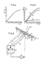
- the illuminance Ea is plotted in klx over the height angle ⁇ of the position of the sun when the sky is overcast. As the curve shows, the illuminance Ea does not yet reach 22 klx even at the highest position of the sun. It looks very different when the sky is uncovered.
- the corresponding diagram is shown in FIG. 5.
- the illuminance Ea above the elevation angle ⁇ is indicated here by the curve eo, which is composed of the proportion that comes from the sky and the proportion that comes from the sun.
- the sky component is represented by curve e2 and the sun component by curve e1.
- an illuminance Ea of 25 klx is already reached at an elevation angle ⁇ of about 15 ° above the horizon.
- a flawless control criterion is thus achieved when using light sensors on the underside of a slat if the response threshold for the automatic readjustment is set so high that the control electronics are activated only when the sunlight passing through the slat is of sufficient intensity and the adjustment process is ended as soon as the illuminance at the light sensors falls below the response threshold again.
- an illuminance Ea of around 25 klx represents a preferred response value.
- the arrangement of the light sensor arrangement 2 on the underside 12 of a lamella 1 corresponding to FIG. 2 is shown in FIG. 6.
- the two in terms of their electrical Characteristic data of the same light sensors 21 and 22 are arranged opposite one another on the two cathets 120 of the prism 100, which receives the longitudinal axis 10 about which the lamella 1 can be rotated.
- the light sensors 21 and 22 representing optoelectronic transducers emit an electrical variable corresponding to the illuminance Ea via the connecting line AL to two threshold value switches sv1 and sv2 on the input side of the control electronics ST.
- Each of the two threshold switches is assigned a specific direction of rotation for the drive A to be controlled.
- the inclination angle ⁇ of the lamella 1 against the horizontal is then and in the rotation direction specified by the responsive threshold switch sv1 or sv2 until the illuminance Ea on the light sensor 21 or 22 associated with the responsive threshold switch is again below the predefined one Response value of 25 klx has dropped, ie the retroreflection of the lamella with respect to the incident sun rays SS is fulfilled again.
- the response threshold of the threshold switches sv1 and sv2 of the control electronics ST can be implemented in a simple manner by means of an adjustable reference voltage value with which the voltage values emitted by the light sensors 21, 22 are compared, which are proportional to the measured illuminance, and, depending on the comparison, an adjustment of the inclination angle ⁇ if necessary the slat 1 is brought about.
- controllable sun protection devices come especially for windows with south-facing facades of buildings as well as with light openings roofs.
- the slats are arranged in the space between two glass panes and thus protected from moisture and dust.
Landscapes
- Engineering & Computer Science (AREA)
- Structural Engineering (AREA)
- Architecture (AREA)
- Civil Engineering (AREA)
- Blinds (AREA)
- Hydrogenated Pyridines (AREA)
- Transition And Organic Metals Composition Catalysts For Addition Polymerization (AREA)
- Window Of Vehicle (AREA)
- Details Of Indoor Wiring (AREA)
- Non-Portable Lighting Devices Or Systems Thereof (AREA)
- Photometry And Measurement Of Optical Pulse Characteristics (AREA)
- Circuit Arrangement For Electric Light Sources In General (AREA)
- Amplifiers (AREA)
- Steering Control In Accordance With Driving Conditions (AREA)
- Revetment (AREA)
Priority Applications (1)
| Application Number | Priority Date | Filing Date | Title |
|---|---|---|---|
| AT87109464T ATE50618T1 (de) | 1986-07-04 | 1987-07-01 | Sonnenschutzeinrichtung. |
Applications Claiming Priority (2)
| Application Number | Priority Date | Filing Date | Title |
|---|---|---|---|
| DE3622564 | 1986-07-04 | ||
| DE3622564 | 1987-07-04 |
Publications (2)
| Publication Number | Publication Date |
|---|---|
| EP0251311A1 true EP0251311A1 (fr) | 1988-01-07 |
| EP0251311B1 EP0251311B1 (fr) | 1990-02-28 |
Family
ID=6304434
Family Applications (1)
| Application Number | Title | Priority Date | Filing Date |
|---|---|---|---|
| EP87109464A Expired - Lifetime EP0251311B1 (fr) | 1986-07-04 | 1987-07-01 | Dispositif de protection solaire |
Country Status (7)
| Country | Link |
|---|---|
| US (1) | US4841672A (fr) |
| EP (1) | EP0251311B1 (fr) |
| JP (1) | JPS6322984A (fr) |
| AT (1) | ATE50618T1 (fr) |
| AU (1) | AU585456B2 (fr) |
| DE (1) | DE3761778D1 (fr) |
| ES (1) | ES2014277B3 (fr) |
Cited By (2)
| Publication number | Priority date | Publication date | Assignee | Title |
|---|---|---|---|---|
| DE19540289A1 (de) * | 1995-10-28 | 1997-04-30 | Seele Gmbh | Winkelselektives Verschattungselement |
| DE4442870C2 (de) * | 1994-09-17 | 2003-10-16 | Helmut Koester | Lamelle zur präzisen Steuerung der direkten Sonneneinstrahlung |
Families Citing this family (19)
| Publication number | Priority date | Publication date | Assignee | Title |
|---|---|---|---|---|
| JPH01122196U (fr) * | 1988-02-12 | 1989-08-18 | ||
| JPH0712637Y2 (ja) * | 1988-02-12 | 1995-03-29 | ワイケイケイ株式会社 | 電動遮閉装置の太陽電池パネル取付装置 |
| DE8805107U1 (fr) * | 1988-04-18 | 1988-06-23 | Siemens Ag, 1000 Berlin Und 8000 Muenchen, De | |
| DE4032221A1 (de) * | 1990-10-11 | 1992-04-16 | Warema Renkhoff Gmbh & Co Kg | Verfahren und vorrichtung zum steuern von raffstores |
| US5204777A (en) * | 1992-01-23 | 1993-04-20 | Sea Corporation | Energy efficient skylight and blind |
| AU704884B2 (en) * | 1994-09-17 | 1999-05-06 | Helmut Koster | Stepped lamella for guiding light radiation |
| US5663621A (en) * | 1996-01-24 | 1997-09-02 | Popat; Pradeep P. | Autonomous, low-cost, automatic window covering system for daylighting applications |
| US5598000A (en) * | 1996-02-22 | 1997-01-28 | Popat; Pradeep P. | Dual-mode automatic window covering system responsive to AC-induced flicker in ambient illumination |
| AT411613B (de) * | 1997-12-09 | 2004-03-25 | Koster Helmut | Sonnenschutzanlage mit sonnenschutzlamellen, die eine gezahnte oberseite aufweisen |
| US6105318A (en) * | 1998-09-11 | 2000-08-22 | Harrison; Janet | Seasonally selective passive solar shading system |
| EP1877741B1 (fr) * | 2005-05-04 | 2010-08-11 | Preh GmbH | Dispositif pour detecter de la lumiere du milieu environnant et du champ avant dans une automobile |
| US20080029149A1 (en) * | 2006-08-02 | 2008-02-07 | Daniel Simon | Method and apparatus for arranging a solar cell and reflector |
| FR2922938B1 (fr) * | 2007-10-31 | 2009-12-11 | Somfy Sas | Procede de commande automatisee d'une installation d'ecran de protection solaire comportant des lames de type retro-reflechissant. |
| KR20100072941A (ko) * | 2008-12-22 | 2010-07-01 | 삼성전자주식회사 | 태양전지를 구비한 블라인드 및 그 제어방법 |
| US9933761B2 (en) * | 2012-11-30 | 2018-04-03 | Lutron Electronics Co., Inc. | Method of controlling a motorized window treatment |
| US10017985B2 (en) * | 2013-08-14 | 2018-07-10 | Lutron Electronics Co., Inc. | Window treatment control using bright override |
| EP3026365B1 (fr) | 2014-11-25 | 2018-01-03 | Marcelo Ymbern | Système actif de redirection de lumière solaire |
| US20190113196A1 (en) | 2016-04-04 | 2019-04-18 | Marcelo Ymbern | Active sunlight redirection system |
| US10538964B2 (en) * | 2016-04-27 | 2020-01-21 | Sharp Kabushiki Kaisha | Daylighting device and daylighting system |
Citations (1)
| Publication number | Priority date | Publication date | Assignee | Title |
|---|---|---|---|---|
| EP0199931A1 (fr) * | 1985-04-30 | 1986-11-05 | Siemens Aktiengesellschaft | Dispositif pare-soleil |
Family Cites Families (9)
| Publication number | Priority date | Publication date | Assignee | Title |
|---|---|---|---|---|
| US2225011A (en) * | 1938-04-14 | 1940-12-17 | Lloyd M Jones | Awning shutter |
| US3448273A (en) * | 1966-04-20 | 1969-06-03 | Nasa | Plurality of photosensitive cells on a pyramidical base for planetary trackers |
| US3478219A (en) * | 1968-01-17 | 1969-11-11 | Bendix Corp | Optical prism with multiple photocells |
| US4117325A (en) * | 1975-08-22 | 1978-09-26 | Ernst Leitz Wetzlar Gmbh | Optical objective focus indicator and display |
| US4154219A (en) * | 1977-03-11 | 1979-05-15 | E-Systems, Inc. | Prismatic solar reflector apparatus and method of solar tracking |
| US4223214A (en) * | 1978-01-09 | 1980-09-16 | American Solar Systems, Inc. | Solar tracking device |
| US4486073A (en) * | 1978-06-20 | 1984-12-04 | Boyd Michael D | Radiant energy reflecting structures |
| JPS58501518A (ja) * | 1981-09-25 | 1983-09-08 | バルテンバツハ、クリスチアン | 日除け装置 |
| US4769531A (en) * | 1985-12-05 | 1988-09-06 | Santa Barbara Research Center | Direction finder system with inclined detectors |
-
1987
- 1987-06-06 US US07/069,727 patent/US4841672A/en not_active Expired - Fee Related
- 1987-07-01 DE DE8787109464T patent/DE3761778D1/de not_active Expired - Lifetime
- 1987-07-01 AT AT87109464T patent/ATE50618T1/de not_active IP Right Cessation
- 1987-07-01 EP EP87109464A patent/EP0251311B1/fr not_active Expired - Lifetime
- 1987-07-01 ES ES87109464T patent/ES2014277B3/es not_active Expired - Lifetime
- 1987-07-03 JP JP62165569A patent/JPS6322984A/ja active Pending
- 1987-07-03 AU AU75081/87A patent/AU585456B2/en not_active Ceased
Patent Citations (1)
| Publication number | Priority date | Publication date | Assignee | Title |
|---|---|---|---|---|
| EP0199931A1 (fr) * | 1985-04-30 | 1986-11-05 | Siemens Aktiengesellschaft | Dispositif pare-soleil |
Cited By (2)
| Publication number | Priority date | Publication date | Assignee | Title |
|---|---|---|---|---|
| DE4442870C2 (de) * | 1994-09-17 | 2003-10-16 | Helmut Koester | Lamelle zur präzisen Steuerung der direkten Sonneneinstrahlung |
| DE19540289A1 (de) * | 1995-10-28 | 1997-04-30 | Seele Gmbh | Winkelselektives Verschattungselement |
Also Published As
| Publication number | Publication date |
|---|---|
| ATE50618T1 (de) | 1990-03-15 |
| AU7508187A (en) | 1988-01-07 |
| DE3761778D1 (de) | 1990-04-05 |
| ES2014277B3 (es) | 1990-07-01 |
| EP0251311B1 (fr) | 1990-02-28 |
| JPS6322984A (ja) | 1988-01-30 |
| AU585456B2 (en) | 1989-06-15 |
| US4841672A (en) | 1989-06-27 |
Similar Documents
| Publication | Publication Date | Title |
|---|---|---|
| EP0251311B1 (fr) | Dispositif de protection solaire | |
| EP0480119B1 (fr) | Méthode et dispositif de contrôle des stores vénitiens | |
| EP0199931B1 (fr) | Dispositif pare-soleil | |
| EP0786623B1 (fr) | Dispositif pour éclairer une pièce à partir d'une lumiére solaire non-aveuglante et diffuse | |
| DE2009372C3 (de) | Abdeckvorrichtung für Lichtöffnungen | |
| EP0956423B1 (fr) | Dispositif de protection contre le soleil de type store venitien | |
| EP0090830B1 (fr) | Dispositif de protection contre la lumiere solaire | |
| EP0524388B1 (fr) | Dispositif d'éclairage naturel | |
| DE4442870A1 (de) | Jalousielamelle zur präzisen Steuerung der direkten Sonneneinstrahlung | |
| DE2615379A1 (de) | Abschirmung fuer lichtoeffnungen, fenster und dergleichen | |
| DE4310718A1 (de) | Vorrichtung zur automatischen Steuerung des Lichteinfalls in einen Raum | |
| DE3020097C2 (de) | Signalleuchte | |
| DE4225007C2 (de) | Oberlicht | |
| DE3227118C2 (de) | Fenster | |
| DE3122164C2 (fr) | ||
| DE19538651B4 (de) | Sonnenschutzvorrichtung aus einem für Sonnenlicht transparenten Material | |
| DE60007780T2 (de) | Sonnenschutzvorrichtung nach der art einer lamellenjalousie | |
| DE3906229A1 (de) | Indirektbeleuchtung unterstuetztes tageslichtsystem | |
| WO1997019246A2 (fr) | Dispositif de protection solaire | |
| DE3226709A1 (de) | Sonnenschutzeinrichtung | |
| DE10202830A1 (de) | Vorrichtung zum Verstellen von Lichttechnikelementen | |
| DE1759280B1 (de) | Oberlichtsonnenschutzblende mit einer Mehrzahl zueinander paralleler,lichtreflektierender Lamellen | |
| DE2936295C2 (de) | Beleuchtungseinrichtung zur Ausleuchtung eines eine reflektierende Decke aufweisenden Raumes mit Tageslicht | |
| DE4211083A1 (de) | Vorrichtung zur automatischen Steuerung des Lichteinfalls in einen Raum | |
| DE19823758A1 (de) | Sonnenschutzvorrichtung zur Beschattung von mit transparenten Fassadenanteilen versehenen Gebäudefassaden |
Legal Events
| Date | Code | Title | Description |
|---|---|---|---|
| PUAI | Public reference made under article 153(3) epc to a published international application that has entered the european phase |
Free format text: ORIGINAL CODE: 0009012 |
|
| AK | Designated contracting states |
Kind code of ref document: A1 Designated state(s): AT CH DE ES FR GB IT LI |
|
| 17P | Request for examination filed |
Effective date: 19880705 |
|
| 17Q | First examination report despatched |
Effective date: 19890807 |
|
| GRAA | (expected) grant |
Free format text: ORIGINAL CODE: 0009210 |
|
| AK | Designated contracting states |
Kind code of ref document: B1 Designated state(s): AT CH DE ES FR GB IT LI |
|
| REF | Corresponds to: |
Ref document number: 50618 Country of ref document: AT Date of ref document: 19900315 Kind code of ref document: T |
|
| REF | Corresponds to: |
Ref document number: 3761778 Country of ref document: DE Date of ref document: 19900405 |
|
| ET | Fr: translation filed | ||
| ITF | It: translation for a ep patent filed |
Owner name: STUDIO JAUMANN |
|
| GBT | Gb: translation of ep patent filed (gb section 77(6)(a)/1977) | ||
| PGFP | Annual fee paid to national office [announced via postgrant information from national office to epo] |
Ref country code: AT Payment date: 19900704 Year of fee payment: 4 |
|
| PGFP | Annual fee paid to national office [announced via postgrant information from national office to epo] |
Ref country code: FR Payment date: 19900724 Year of fee payment: 4 |
|
| PGFP | Annual fee paid to national office [announced via postgrant information from national office to epo] |
Ref country code: ES Payment date: 19900731 Year of fee payment: 4 |
|
| PGFP | Annual fee paid to national office [announced via postgrant information from national office to epo] |
Ref country code: CH Payment date: 19901024 Year of fee payment: 4 |
|
| PLBE | No opposition filed within time limit |
Free format text: ORIGINAL CODE: 0009261 |
|
| STAA | Information on the status of an ep patent application or granted ep patent |
Free format text: STATUS: NO OPPOSITION FILED WITHIN TIME LIMIT |
|
| 26N | No opposition filed | ||
| PG25 | Lapsed in a contracting state [announced via postgrant information from national office to epo] |
Ref country code: GB Effective date: 19910701 Ref country code: AT Effective date: 19910701 |
|
| PG25 | Lapsed in a contracting state [announced via postgrant information from national office to epo] |
Ref country code: ES Free format text: LAPSE BECAUSE OF THE APPLICANT RENOUNCES Effective date: 19910702 |
|
| ITTA | It: last paid annual fee | ||
| PG25 | Lapsed in a contracting state [announced via postgrant information from national office to epo] |
Ref country code: LI Effective date: 19910731 Ref country code: CH Effective date: 19910731 |
|
| GBPC | Gb: european patent ceased through non-payment of renewal fee | ||
| PG25 | Lapsed in a contracting state [announced via postgrant information from national office to epo] |
Ref country code: FR Effective date: 19920331 |
|
| REG | Reference to a national code |
Ref country code: CH Ref legal event code: PL |
|
| REG | Reference to a national code |
Ref country code: FR Ref legal event code: ST |
|
| REG | Reference to a national code |
Ref country code: ES Ref legal event code: FD2A Effective date: 19991007 |
|
| PGFP | Annual fee paid to national office [announced via postgrant information from national office to epo] |
Ref country code: DE Payment date: 20000803 Year of fee payment: 14 |
|
| PG25 | Lapsed in a contracting state [announced via postgrant information from national office to epo] |
Ref country code: DE Free format text: LAPSE BECAUSE OF NON-PAYMENT OF DUE FEES Effective date: 20020501 |
|
| PG25 | Lapsed in a contracting state [announced via postgrant information from national office to epo] |
Ref country code: IT Free format text: LAPSE BECAUSE OF NON-PAYMENT OF DUE FEES;WARNING: LAPSES OF ITALIAN PATENTS WITH EFFECTIVE DATE BEFORE 2007 MAY HAVE OCCURRED AT ANY TIME BEFORE 2007. THE CORRECT EFFECTIVE DATE MAY BE DIFFERENT FROM THE ONE RECORDED. Effective date: 20050701 |