EP0251026B1 - Method for containing fluid or solid materials using a pressure barrier liner; methods for contructing and testing such a liner - Google Patents
Method for containing fluid or solid materials using a pressure barrier liner; methods for contructing and testing such a liner Download PDFInfo
- Publication number
- EP0251026B1 EP0251026B1 EP87108665A EP87108665A EP0251026B1 EP 0251026 B1 EP0251026 B1 EP 0251026B1 EP 87108665 A EP87108665 A EP 87108665A EP 87108665 A EP87108665 A EP 87108665A EP 0251026 B1 EP0251026 B1 EP 0251026B1
- Authority
- EP
- European Patent Office
- Prior art keywords
- membranes
- region
- liner
- membrane
- high permeability
- Prior art date
- Legal status (The legal status is an assumption and is not a legal conclusion. Google has not performed a legal analysis and makes no representation as to the accuracy of the status listed.)
- Expired - Lifetime
Links
Images


Classifications
-
- E—FIXED CONSTRUCTIONS
- E02—HYDRAULIC ENGINEERING; FOUNDATIONS; SOIL SHIFTING
- E02D—FOUNDATIONS; EXCAVATIONS; EMBANKMENTS; UNDERGROUND OR UNDERWATER STRUCTURES
- E02D31/00—Protective arrangements for foundations or foundation structures; Ground foundation measures for protecting the soil or the subsoil water, e.g. preventing or counteracting oil pollution
- E02D31/002—Ground foundation measures for protecting the soil or subsoil water, e.g. preventing or counteracting oil pollution
- E02D31/004—Sealing liners
Definitions
- This application pertains to pressure barrier liners for containment of valuable and/or hazardous and/or polluting fluid or solid waste materials. More particularly, the application pertains to pressure barrier liners having membranes which encapsulate regions of relatively high permeability such that the regions may be pressurized or depressurized to pressure levels sufficient to create a barrier which substantially prevents fluid escapement through the liner. Pressure barrier liners constructed in accordance with the invention may also be tested to assess their integrity, to determine whether they are leaking, and to assess their capability to retain fluids or prevent leakage in the absence of such pressurization or depressurization.
- Membrane or sheet liners are commonly used to line excavations or other containment facilities to prevent escapement therefrom of hazardous and/or polluting fluid wastes, solid waste leachates or valuable fluids. Such materials must be stored at the lowest possible cost on either a short term or a long term basis.
- Membrane liners consist of a number of membranes or flexible sheets of liner material joined together at their edges and joined to bounding structures to yield a continuous liner interposed between the fluid to be contained and the surroundings into which flow of the contained fluid is to be prevented.
- Conventional membrane liners have a finite permeability and may suffer from a number of imperfections including holes in the membrane or sheet material which are inadvertently produced during manufacture of the material; holes which are inadvertently caused during the process of construction of the liner from the sheet or membrane material or during the process of installing the liner in the excavation or other containment region; imperfections in the welds or seams used to join adjacent segments of membrane or sheet material to form the liner; and, holes which develop in the liner after it is installed, due to punching, shearing, settling, chemical attack and a variety of other causes.
- Liners are conventionally subjected to fluid pressures from both sides of the liner. Ambient air pressure subjects both sides of the liner to a first fluid pressure. Since this pressure is normally equal on both sides of the liner it does not produce a significant pressure gradient across the liner and therefore does not induce significant flow through the liner. Fluids contained in the region above the liner exert a second fluid pressure on the upper surface of the liner. Ground water in the region beneath the liner exerts a third fluid pressure on the lower surface of the liner. Accordingly, liners are conventionally subjected to fluid pressure gradients caused by the differential between the second and third fluid pressures.
- all liners have a finite permeability due to the inherent porosity of the material used to construct the liner. Accordingly, all liners leak at a small but finite rate. If holes are inadvertently made in the liner, or if the seams which join adjacent segments of liner material are imperfect, then the rate of leakage may increase dramatically and it is such increased leakage which is desirably prevented.
- high security composite liners have been constructed with double or even triple layers of liner material as witness, for instance, East German Patent 79452. Drainage layers are typically established between layers of liner material. Fluid which escapes through the uppermost liner passes into the drainage layer beneath the uppermost liner and flows towards drainage collection points established in the drainage layer.
- the underlying problem of the present invention is providing a pressure barrier liner which significantly reduces the possibility of leakage through the liner, while facilitating testing of the liner to determine whether leakage could occur through the liner, even at relatively low leakage rates.
- the present invention relates to a method for containing valuable and/or hazardous and/or fluid or solid waste materials or the like using a liner having the features set forth in the pre-characterising portion of Claim 1, which is known per se e.g. from WO-A-86/01554.
- a liner having the features set forth in the pre-characterising portion of Claim 1, which is known per se e.g. from WO-A-86/01554.
- samples of the atmosphere in the region between the low permeability flexible membranes can be taken continuously or periodically be means of a vacuum connection.
- Such an arrangement does not provide for an under or overpressure to be maintained within the liner to prevent or control leakage.
- a double liner is known wherein hydrostatic liquid pressure is maintained in an intermediate granular fill to control leakage of the contained fluid.
- such an arrangement only provides for fluid to be extracted from the granular fill to detect a possible leak in the inner seal.
- the invention provides a liner comprising a plurality of low permeability flexible membranes disposed one above the other. Separate regions of relatively high permeability are encapsulated between each adjacent pair of membranes.
- a pressurizing means may be used to pressurize using gas a selected group of the high permeability regions to a selected pressure or pressures.
- a depressurizing means may also or may alternatively be used to depressurize using gas a selected group of the high permeability regions to a selected pressure or pressures.
- a relatively high permeability flexible membrane may be disposed outside the outermost of the low permeability membranes to encapsulate a region of relatively high permeability between the high permeability membrane and at least one outer surface of the liner.
- a depressurizing means may be provided for depressurizing the region between the high permeability membrane and the liner outer surface.
- the encapsulated high permeability regions may contain a relatively high permeability core material which may be connected to the adjacent membranes which encapsulate the material to give the liner sufficient strength to resist tensile stresses which could cause the membranes to separate.
- the membrane inner surfaces may be textured such that contact between the surfaces does not obstruct fluid flow within the encapsulated region. The textured surfaces may also be connected together to enable the liner to resist tensile stresses.
- a drainage means may extend within a selected group of the high permeability regions for withdrawing liquids from within those regions.
- a layer of geotextile material may be disposed outside at least one of the outermost of the membranes to inhibit passage of particulate materials into the liner.
- a composite liner for use in the invention may be constructed by providing a first plurality of low permeability flexible membranes disposed one above the other with separate regions of relatively high permeability encapsulated between each adjacent pair of membranes. For each one of the first plurality of membranes, a second plurality of low permeability membranes is disposed beside said one membrane; and, separate regions of relatively high permeability are encapsulated between each vertically adjacent pair of the second plurality of membranes.
- the liner may be extended to attain any desired size and shape by similarly providing further pluralities of vertically layered membranes beside the existing multiple membrane liner.
- the invention also provides a connector means for sealingly connecting edges of liner membranes dis posed beside one another.
- the connector means further facilitates selective fluid communication between encapsulated high permeability regions.
- the depressurizing means may comprise a vacuum pump for applying a low negative head pressure within a selected group of high permeability regions.
- the invention also provides a method of constructing a liner for use in the invention, as called for in Claim 11 as well as a method of testing for leakage of a liner during construction of the liner as called for in Claim 12.
- the method comprises the steps of disposing first and second low permeability membranes one above the other to encapsulate a region of relatively high permeability therebetween.
- the high permeability region is then pressurized or depressurized using gas to a selected pressure (alternatively, a detectable gas is injected into the high permeability region).
- the pressure within the region is then monitored (or the region is monitored for escape of detectable gas therefrom). If the region maintains pressure (or contains the detectable gas) then it may be determined that the membranes are not leaking.
- the region fails to maintain the selected pressure (or fails to contain the detectable gas) then the uppermost of the membranes is inspected to locate leaks therein which are then repaired.
- the pressurization and monitoring steps are then repeated. If the region still fails to maintain the selected pressure (or to contain the detectable gas) then the lowermost membrane is inspected to locate leaks therein which are then repaired.
- a further low permeability membrane is then disposed above the uppermost membrane to encapsulate a further high permeability region between the further and uppermost membranes.
- the pressurization, monitoring, inspecting and repair steps are then repeated with respect to the further high permeability region so established. Additional low permeability membranes are then added and tested as aforesaid until the liner comprises a selected plurality of low permeability membranes disposed one above the other with separate regions of relatively high permeability encapsulated between each adjacent pair of membranes.
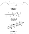
- Figure l is a simplified cross-sectional side view of a typical prior art liner positioned within an excavation to contain fluid in a containment pond.
- Figure 2 is a simplified diagram which illustrates the potential escapement of fluids through holes or imperfect seams in the liner of Figure l.
- Figure 3 is a simplified cross-sectional side view of a portion of a prior art liner having inner and outer membranes and having a drainage layer between the membranes.
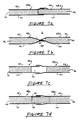
- Figure 4 is a cross-sectional side view of a portion of a dual membrane pressurized liner.
- Figure 5 is a somewhat enlarged cross-sectional side view of a portion of the liner of Figure 4.
- Figure 6 is a cross-sectional side view of a portion of a dual membrane depressurized liner.
- FIGS 7a through 7f illustrate alternative liner panel joints.
- Figures 8a and 8c are, respectively, diagramatic top plan illustrations of a portion of a dual membrane liner incorporating alternative embodiments of a connecting strip for selective fluid communication between regions within adjacent liner panels and for sealingly engaging the edges of the first and second membranes of adjacent liner panels.
- Figure 8b is a cross-sectional view with respect to line A-A of Figure 8a.
- Figure 8d is a cross-sectional view with respect to line B-B of Figure 8c.
- Figures 9a through 9d are, respectively, cross-sectional end views of alternative connecting strips.
- Figure l0a is a top plan view of a containment pond having a multiple cell dual membrane liner which has been shaped and sized to fit the containment pond excavation.
- Figure l0b is a cross-sectional view taken with respect to line A-A of Figure l0a.
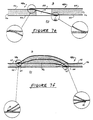
- Figure ll illustrates the manner in which the inner surfaces of the membranes comprising a liner constructed in accordance with the invention may be channelled or otherwise textured such that contact between the membrane inner surfaces does not obstruct fluid flow between the membrane inner surfaces.
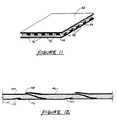
- Figure l2 illustrates a "shingling" technique for constructing and progressively testing a liner in accordance with the invention.
- Figure l3 illustrates a connector strip which is specially adapted to the construction of liners in accordance with the "shingling" technique of Figure l2.
- Figure l4 is a cross-sectional side view of a portion of a triple membrane liner.
- Figure l5 is a cross-sectional side view of a portion of a quadruple membrane liner.
- Figure l6 is a cross-sectional side view of a connecting strip adapted to the construction of multiple membrane liners.
- Figure l7 is similar to Figure ll, but illustrates a multiple membrane liner.
- Figures l8a and l8b illustrate two stages in the contruction of a multiple membrane liner.
- Figure l9 illustrates the operation of a leaking dual membrane depressurized liner.
- Figure 20 illustrates the operation of a leaking quadruple membrane liner having depressurized outer segments and a pressurized or non-pressurized inner segment.
- Figure 2l illustrates operation of a leaking triple membrane liner in which both liner segments are depressurized; the degree of vacuum in the upper liner segment exceeding that in the lower liner segment.
- Figure 22 illustrates operation of a leaking triple membrane liner in which both liner segments are pressurized; the pressure in the lower liner segment exceeding that in the upper liner segment.
- Figure 23 illustrates operation of a leaking triple membrane liner in which the lower liner segment is pressurized and the upper liner segment is depressurized.
- Figure 24 illustrates the provision of a high permeability flexible membrane beneath the lowermost low permeability liner membrane to facilitate fluid drainage from beneath the liner.
- Dual membrane pressurized and depressurized liners will then be described, together with techniques for joining adjacent liner panels to construct liners of desired sizes and shapes. Techniques for liner leakage detection will then be described. A detailed description of connecting strips will then be provided in the context of dual membrane liners. A "shingling" technique for constructing dual membrane liners is then described. This is followed by a description of a dual membrane liner having multiple cells. Multiple membrane liners are then described, together with connecting strips and leakage detection and liner construction techniques specifically adapted to multiple membrane liners.
- Figure l illustrates a prior art fluid containment pond comprising excavation l0 which is surrounded by embankment l2 and lined with a liner l4 formed of material such as polyvinyl chloride, high or low density polyethylene, butyl rubber, chlorinated polyethylene, elasticized polyolefin, polyamide, chlorosulphonated polyethylene, or other material suitable for potential long term containment of valuable, hazardous or pollutant fluid l6.
- liner l4 is formed by joining together several segments or sheets of liner material using heat welding, extrusion welding, solvent welding or bonding, adhesive bonding, ultrasonic welding, dielectric welding, electro-magnetic welding, or other known techniques for joining such materials to form a single composite liner.
- holes l8 may be inadvertently made in liner l4 during manufacture of the liner material, during formation of the liner, during installation of the liner, or after the liner has been installed; thereby allowing fluid l6 to leak through hole l8 into the region 20 beneath liner l4, which is desirably avoided.
- imperfections in the seams or welds used to join adjacent sheets or segments of liner material together may result in flow channels or paths as illustrated by reference number 22 in Figure 2, enabling further leakage of fluid l6 through liner l4 and into region 20.
- Figure 3 is a cross-sectional side view of a portion of a prior art double liner having first and second liners 24, 26 between which a drainage layer 28 formed of material such as sand is established.
- holes 30, 32 and/or seam/weld imperfections 34, 36 can result in escapement of fluid l6 through liner 24 into drainage layer 28 and thence through liner 26 into region 20 if the pressure P1 exerted on liner 24 by fluid l6 exceeds the pressure P2 exerted on liner 26 by fluid in region 20. If a drainage system is installed in drainage layer 28 then a reduced pressure "P3" results in drainage layer 28.
- P3 is always positive and may be increased where the geometry or the permeability of drainage layer 28 is such that increased pressure heads are required to achieve the flow rates necessary to drain fluids which enter drainage layer 28 through holes/imperfections 30, 34 in first liner 24. If P1 is greater than P3, and if P3 is greater than P2, then fluid l6 will flow through holes 30 and seam imperfections 34 into drainage layer 28; part of which flow will be drained away by the drainage system and part of which will escape through second liner 26 through holes 32 and seam imperfections 36 to region 20. In practice, P2 is seldom greater than P3 over the entire extent of second liner 26.
- FIG. 4 illustrates a dual membrane pressure barrier liner 38 comprising a plurality of liner panels 40a, 40b, 40c, etc.
- Each liner panel in turn comprises dual (i.e. first and second) low permeability flexible membranes 42, 44 disposed one above the other.
- the term "above” is used in the relative sense.
- Membranes 42, 44 may for example be oriented one beside the other if liner 38 is placed against a vertical sidewall of a containment pond.
- membranes 42, 44 may be formed of any suitable material such as high or low density polyethylene, polyvinyl chloride, chlorinated polyethylene, elasticized polyolefin, polyamide, chlorosulphonated polyethylene, rubbers, Hypalon, butyl rubber, asphalt, concrete, soil cement or other suitable low permeability materials.
- low permeability means a material having an overall permeability of less than l ⁇ l0 ⁇ 7 cm/sec. relative to the flow of water and may ideally be as low as l ⁇ l0 ⁇ 15 cm/sec.
- a relatively high permeability core material 46 such as sand, geonet, geotextile, textured sheet, or other open-pore material having a permeability greater than approximately l ⁇ l0 ⁇ 3 cm/sec. relative to water is encapsulated between first and second membranes 42, 44.
- Opposed first and second surfaces of permeable core material 46 are preferably (but not necessarily) connected to the inner surfaces of first and second membranes 42, 44 respectively to resist the effective tensile and compressive stresses between membranes 42, 44. If the effective normal stress between membranes 42, 44 is negative, then the membranes will tend to separate.
- the mechanical connection established by connecting core material 46 to membranes 42 and 44 must be capable of withstanding an average tensile stress which is equal to the effective normal tensile stress between the membranes.
- the effective normal stress between membranes 42, 44 is compressive
- permeable core material 46 is subjected to compressive stress which it must be able to withstand without crushing to the extent that the permeability of core material 46 is reduced to the point that fluid pressure cannot be distributed throughout the region between membranes 42 and 44.
- a pressurizing means such as a pump (not shown) is used to introduce a pressurized gas such as air or other environmentally acceptable gas into the region encapsulated between first and second membranes 42, 44.
- a pressurized gas such as air or other environmentally acceptable gas
- the highly permeable core material 46 allows the pressurized gas to distribute throughout the region encapsulated between membranes 42, 44.
- fluid distribution conduits 58 may be placed within or adjacent to core material 46.
- Conduits 58 may comprise slotted or perforated pipes, channels or other conduit material suitable for fluid transmission.
- any leakage of fluid through disruptions caused by holes or weld/seam imperfections in either of membranes 42, 44 will consist of escapement of environmentally acceptable pressurizing gas from the region between membranes 42, 44 into the region which contains fluid l6, or into region 20. More particularly, leakage of fluid l6 into the region between membranes 42, 44 is prevented by maintaining the pressure within that region in excess of P1, thereby preventing escapement of fluid l6 through liner 38.
- the pressurizing means may maintain a small differential overpressure (less than 2 psi.) within the region between membranes 42, 44 independent of the level of fluid l6 above liner 38. This slight overpressure would require only a small coverload to be maintained on upper membrane 42 (for example, by placing a shallow layer of soil or gravel on top of upper membrane 42) sufficient to prevent membranes 42, 44 from separating, in which case the cost and labour involved in establishing a mechanical connection between core material 46 and membranes 42, 44 may be avoided.
- Gas pressurization ensures uniform pressurization throughout the encapsulated region and is particularly well suited to situations where a drainage layer such as a leachate collection system of the sort typically employed at land fill sites is installed above the uppermost liner membrane. In such situations, the contained fluid exerts only a low pressure head P1 on the upper liner surface which can easily be offset by a higher gas pressure within the liner. Gas pressurization is also relevant in situations where introduction of additional fluids of any sort into fluid l6 cannot be permitted; or where introduction of fluid of any sort into region 20 is undesirable.
- Core material 46 is not essential. One need only ensure that a region of relatively high permeability is encapsulated between membranes 42, 44.
- the inner surfaces of membranes 42, 44 may be channelled as shown in Figure ll. Ridges 90 which separate channels 92 in each of membranes 42, 44 contact one another and hold the membranes away from channels 92, thereby ensuring that contact between the membrane inner surfaces does not obstruct fluid flow within channels 92. It is expected that channelled membrane material may be easily and inexpensively fabricated in large quantities and that liners may be easily and inexpensively constructed of such material due to the elimination of the core material.
- channelled membrane material may be more easily and inexpensively connected together to resist bursting of the pressurized liner than would be the case if core material were disposed between the membranes, since both sides of the core material must be connected to the inner membrane surfaces.
- the membrane material may be striated, stippled, rippled, or otherwise manufactured with a randomly textured surface such that the inner surfaces of adjacent textured membranes are supported away from one another to prevent obstruction of fluid flow within the region encapsulated by the membranes.
- a further alternative liner fabrication technique would be to pass a sheet of relatively high permeability material between a pair of heated rollers to seal the outer surfaces of the material against fluid permeability and then seal the material around its outer edges to encapsulate the high permeability material.
- Surface sealants or other methods of developing low permeability characteristics in the outer surfaces could be used instead of passage between heated rollers.
- the term "low permeability membrane” includes a material surface in which low permeability characteristics have been developed as aforesaid.
- Figure 5 provides a more detailed cross-sectional side view of a portion of a dual membrane pressure barrier liner 38 employing encapsulated core material 46.
- Adjacent liner panels 48a, 48b, etc. each comprise first and second membranes 42, 44 as in the embodiment of Figure 4.
- a relatively high permeability core material 46 is encapsulated between first and second membranes 42, 44 and has first and second surfaces which are preferably (but not necessarily) connected to first and second membranes 42, 44 to resist the effective tensile and compressive stresses aforesaid.
- Adjacent liner panels 48a and 48b are joined together by overlapping and sealing together adjacent edges of the first membranes 42 of each of panels 48a and 48b and by overlapping and sealing together adjacent edges of the second membranes 44 of each of panels 48a, 48b.
- This method of joining panels 48a, 48b facilitates fluid communication between the regions between first and second membranes 42, 44 of each of panels 48a, 48b.
- Such fluid communication enables distribution of pressurized fluid between adjacent liner panels, thereby reducing the need for separate conduits for distributing pressurized gas throughout the liner.
- Membranes 42, 44 of the outermost liner panels are sealed together around their outer edges 76 to prevent loss of pressurized gas and to encapsulate core material 46.
- Figures 7a through 7f illustrate a variety of alternative techniques by means of which adjacent liner panels 48a, 48b may be joined together.
- Figure 7b shows a lap joint in which the outer edges of membranes 42, 44 of each panel 48a, 48b are joined together along their inside surfaces before the two panels are joined together by joining the lower surface of the lower membrane 44 of panel 48b to the upper surface of the upper membrane 42, of panel 48a.
- Figures 7c and 7d illustrate the manner in which high permeability material 46 within each of panels 48a, 48b may be inwardly recessed to leave a gap 50 between the overlapped, sealed panel edges.
- the gap serves as a flow conduit for distribution of pressurized gas throughout the liner.
- gap 50 may be filled with an insert 52 formed of the same high permeability material disposed between the membranes comprising each of liner panels 48a, 48b to provide continuity of core material 46.
- gap 50 may receive a conduit insert which serves as a means for fluid communication between the regions within adjacent liner panels, as hereinafter explained with reference to Figure 8.
- Figures 7e and 7f illustrate lap joints which may in some situations be preferred to the butt joints illustrated in Figures 7a and 7c through 7d. More particularly, Figure 7e shows how the first membrane 42 of each of liner panels 48a, 48b may comprise a single continuous membrane. The second membranes 44 of each of liner panels 48a, 48b may each then comprise discrete membranes which are overlapped in the manner shown in Figure 7e.
- the joint shown in Figure 7e isolates and facilitates separate pressurization and testing of the region encapsulated within liner panels 48a and 48b respectively. If pressure testing of both encapsulated regions (conducted in the manner hereinafter explained) indicates that there are no leaks from either encapsulated region, then fluid l6 cannot leak through the liner to region 20.
- the joint of Figure 7e is therefore advantageous for the prevention and detection of leaks, as compared with the lap joint in Figure 7b and may be used to establish isolated sections (cells) in the liner.
- Figure 7f illustrates a lap joint in which the outer edges of membranes 42, 44 of each of panels 48a and 48b are joined together along their inside surfaces before the two panels are overlapped to produce a third high permeability material filled space 56 between panels 48a and 48b.
- the edges of space 56 are sealed by joining the under surface of the lower membrane 44 of panel 48b to the upper surface of the upper membrane 42 of panel 48a at the outer edges of panel 48b and by joining the upper surface of the upper membrane 42 of panel 48a to the lower surface of the lower membrane 44 of panel 48b at the outer edges of panel 48a as shown at 64.
- the regions encapsulated within each of panels 48a, 48b and region 56 may each be pressurized to prevent leakage of fluid l6 into region 20 and to facilitate detection (as hereinafter described) of such leakage.
- Figure 6 illustrates a dual membrane liner which is generally similar to the liner described above with reference to Figures 4 and 5, except that the pressurizing means is replaced with a depressurizing means such as a vacuum pump (not shown) for depressurizing the region encapsulated between first and second membranes 42, 44 to pressures below ambient air pressure, and except that high permeability core material 46, if used, need not be connected to membranes 42, 44 as it preferably (though not necessarily) is if the liner is pressurized.
- fluid distribution conduits 58 (which are preferably, although not necessarily provided) function as a liquid drainage means and extend throughout the region between first and second membranes 42, 44.
- the depressurizing means is coupled to liquid drainage conduit 58 and is operated to maintain the region encapsulated between first and second membranes 42, 44 at a pressure which is less than both P1 and P2. Accordingly, any liquids which pass through disruptions caused by holes or seam/weld imperfections in membranes 42 or 44 are drawn toward drainage conduit 58 and eventually pass into conduit 58, through which they are ultimately removed and/or returned to the containment pond.
- Drainage conduit 58 may comprise geotextile, geonet, slotted pipe, "egg crate waffle” molded conduits or channels, sand, gravel, or other suitable known drainage ducts or materials.
- the dual membrane depressurized liner of Figure 6 may incorporate first and second layers of geotextile material (not shown) disposed above and below the liner to inhibit passage of particulate matter toward the liner which might clog the region encapsulated between the membranes, drainage conduit 58, the vacuum pump, or otherwise interfere with proper operation of the liner.
- the rate at which pressurizing gas must be injected into the region encapsulated between first and second membranes 42, 44 to maintain the pressure in that region constantly above P1 and P2 is a measure of the rate at which fluid is escaping by leakage through either of first or second membranes 42, 44. If this leakage rate is sufficiently low then it may not be necessary to operate the pressurizing means continuously (although it may in some cases be desirable to couple a liquid drainage means to conduits 58 in order to remove liquids which may accumulate within the liner during periods when the pressurizing means is not operated).
- the rate at which the depressurizing means must be operated to maintain the pressure in the region encapsulated between first and second membranes 42, 44 at a constant level which is below P1 and P2 is a measure of the rate at which fluid is leaking through either of first or second membranes 42, 44.
- the measured leakage rate is sufficiently low then it will not be necessary to continually operate the depressurizing means to maintain a reduced pressure (i.e. suction) between first and second membranes 42, 44.
- Suitable pressure sensing means and/or fluid flow rate sensing means may be employed to sense the fluid pressure in to or out of the region between membranes 42, 44 or to sense the rate of fluid flow within that region, thereby providing an indication of the leakage rate.
- fluid flow rate sensing means for sensing fluid flow rates within the encapsulated region may be employed to measure the flow direction and/or velocity of fluid flow within the encapsulated region and thereby pinpoint leaks.
- a plurality of pressure sensing means may be employed to detect pressure gradients within the encapsulated region as a further leak location technique.
- a still further leak detection technique would be to pressurize the liner with a detectable gas and then inspect the liner, or the material above the liner, either visually, or with apparatus specially adapted to detect low concentrations of that gas, thus assisting in pinpointing leaks.
- This technique facilitates detection of leakage in liners which are either uncovered or which are covered by liquids or by permeable solids (i.e.
- Dual membrane liners which are ultimately intended to operate as either pressurized or depressurized liners may be tested before they are placed in service by pressurizing the encapsulated region (or regions in the case of liners having a plurality of liner panels) and then monitoring the pressurized liner as above to detect leakage therefrom. Upon detection of such leakage a sealant may be injected into the encapsulated region.
- the leakage of pressurizing gas through holes or weld/seam imperfections will carry the sealant to the leakage sites and into the holes or weld/seam imperfections, thereby effectively plugging them. It may be necessary to provide sealant injection points and vents at multiple locations on the liner so that sealant can be applied uniformly throughout the liner.
- FIGS 8a and 8b illustrate a "conduit means" or connecting strip 60 which may be formed of suitable rigid or semi-rigid material and to which first and second membranes 42, 44 of adjacent liner panels 48a, 48b may be sealed with the aid of suitable mechanical connectors, heat welding, solvent welding, adhesive bonding or other known joining techniques.
- Connecting strip 60 may include a major aperture 70 which extends longitudinally through conduit 60 and a plurality of branch apertures 72 which extend at an angle to aperture 70.
- apertures 70, 72 facilitate fluid communication between the encapsulated regions within each of liner panels 48a, 48b.
- connecting strip 60 serves as a barrier to flow between the encapsulated regions within each of liner panels 48a, 48b.
- Connecting strip 60 facilitates rapid construction of liners and also eases the ordinarily difficult task of joining segments of liner material together, thus minimizing the occurrence of liner disruptions due to imperfect welds and/or seams.
- Connecting strip 60 may be utilized in either pressurized or depressurized liners. That is, pressurizing gas may be injected through apertures 70, 72 to pressurize liner panels sealed along either side of connecting strip 60. Alternatively, a depressurizing means may be used to depressurize the liner panels by withdrawing fluid from within the liner panels through apertures 70, 72.
- Apertures 72 may in some cases be omitted from either or both sides of connecting strip 60 to prevent fluid communication from aperture 70 to either or both of the liner panels sealed along each side of strip 60. This facilitates isolation of selected liner panels as aforesaid for the establishment of liner cells of different pressures, or, if desired, establishment of separate pressurized and depressurized cells within the same liner and even facilitates the use of different pressurizing and/or depressurizing gases within the same liner.
- connecting strip 60 may be provided with a second longitudinal aperture 82 parallel to aperture 70.
- Aperture 70 may be connected to a series of apertures 72 along one side of strip 60, while aperture 82 is connected to an opposed series of apertures 72 along the opposite side of strip 60. This also facilitates isolation of liner panels sealed along the opposed sides of strip 60 which may then be independently pressurized or depressurized as above.
- Figures 8a and 8b show sealing of liner panels 48a, 48b to connecting strip 60 by overlapping membranes 42, 44 on strip 60 it may in some cases be convenient to seal the edges of liner panels 48a, 48b within grooves provided along opposed sides of an alternative strip 60 ⁇ as shown in Figures 8c and 8d.
- permeable core material 46 extends to the outermost edges of liner panels 48a, 48b then the liner panel edges will be relatively rigid and easily insertable into the grooves for subsequent sealing therein.
- strips 80 ( Figures 9a and 9b) of plastic or other rigid material may be laid over the edges of connecting strips 60 and secured by bolting or riveting through strips 60 and 80.
- connecting strips 60 may be sealed together in end to end fashion or may be connected or fabricated in "T" or other convenient shapes so as to facilitate construction of liners of any desired size or shape.
- Figures l0a and l0b illustrate a liner formed by sealing a plurality of liner panels together with connecting strips so as to provided a "custom" liner of a shape and size which will fit a particular containment pond excavation.
- a particular advantage of the invention is that such prior art liners necessitate the provision of a containment pond excavation having a floor which slopes uniformly toward a sump located at the low point of the floor.
- the cost of constructing such facilities can be high and it is thus expected that considerable time, labour and cost may be saved in terms of construction and floor preparation through exploitation of the invention, which does not require a uniformly sloped excavation floor or sump.
- Figure 9c illustrates a connecting strip 60 having grooves along opposed sides thereof for receiving liner panels 48a, 48b in the manner explained above, and also having thin metallic conductor strips 84 which extend along the opposed inner surfaces of each groove to contact membranes 42, 44 of each liner panel.
- a short duration pulse of high voltage current is applied to conductor strips 84 to heat them and melt the adjacent portions of membranes 42, 44 which, as they cool, are effectively welded within the connector strip grooves, thereby simplifying the time, cost and labour required to secure liner panels 48a, 48b to connector strip 60.
- Figure 9d illustrates a connector strip 60 having staggered lips 6la, 6lb, 63a, 63b along opposite sides of one surface thereof. Lips 6la and 6lb are for sealingly engaging membranes 44 of adjacent liner panels and lips 63a, 63b are for sealingly engaging membranes 42 of the panels.
- the advantage of this configuration is that the operation of sealing each of membranes 42, 44 to connector strip 60 may be carried out from above the strip - it is not necessary to turn the strip or the partially completed liner over to complete the sealing operation.
- Strip 60 of Figure 9d is thus very convenient to use and assists in minimization of leakage at the juncture of the liner panels and connector strips.
- Figure l2 illustrates a "shingling" technique for constructing and progressively testing a liner.
- This technique is expected to be extremely effective for construction of liners having minimal leakage characteristics.
- the technique uses overlapping joints to seal sections of membrane material together to form a continuous liner having a plurality of encapsulated high permeability regions segregated from one another. Undesirable lap joints like that shown in Figure 7b are avoided.
- a first low permeability membrane l50 is laid above a second low permeability membrane l52 placed upon the floor of the containment pond excavation which is to be lined.
- Membrane l52 has a larger surface area than membrane l50 (if need be, membrane l52 is constructed by overlappingly sealing, as at l53, two or more sheets of low permeability membrane material). Membrane l50 is joined around its edges to membrane l52 to encapsulate a region of relatively high permeability between the two membranes. (If desired, high permeability core material may be placed in the encapsulated region, or the membranes may be textured as hereinbefore described. Also, depending upon the pressure to be maintained within the encapsulated region, the inner surfaces of the membranes may be connected together, or connected to any encapsulated core material, before the membranes are joined around their edges).
- the encapsulated region is then pressurized and monitored to detect leakage therefrom. Any leaks detected are repaired; if need be by separating the membranes or, if desired, by injecting sealant material into the encapsulated region to plug the leaks.
- Membrane l52 is then extended by sealing an edge thereof to a further section of low permeability membrane material as shown at l54.
- a further section of low permeability membrane material l56 is then sealed to membrane l50 with edge l58 of section l56 overlapping the joint of membranes l50, l52.
- the remaining edges of membrane l56 are then sealed to the extended lower membrane to encapsulate another high permeability region between membrane l56 and the extended lower membrane.
- the newly encapsulated region is then pressurized, monitored for leaks and repaired as required.
- the process is repeated by further extending the lower membrane and overlapping or "shingling" low permeability membrane sections thereabove until the liner attains its desired size and shape.
- a particular advantage of this technique is that all membrane sealing operations may be conducted from above the liner, thereby simplifying construction. Moreover, if the rightmost edge (as viewed in Figure l2) of each of the upper membrane sections are only temporarily sealed to the lower membrane (i.e. with tape) then the membranes may easily be separated for repair if leaks are detected and then permanently resealed. However, such temporary sealing may entail problems which outweigh its theoretical advantage aforesaid.
- Figure l3 illustrates a connector strip l60 specially adapted to the construction of liners in accordance with the shingling technique of Figure l2.
- the base of connector strip l60 is sealed directly to the upper surface of lower membrane l52 along the site of the desired joint.
- the upper surface of membrane l50 is then sealed to the undersurface of lip l62 which projects to the left of strip l60 as viewed in Figure l3.
- Membrane l56 and any encapsulated core material 46 is then laid over the top of strip l60 and joint l58 is made by sealing the undersurface of membrane l56 to the upper surface of membrane l50.
- Figures l0a and l0b show how the bottom of a containment pond may be lined with a low cost dual membrane liner l00 comprised of membranes which need not be mechanically connected to each other or to any high permeability core material which may be encapsulated between the membranes.
- Bottom liner l00 is joined, around its edges, to a plurality of liner panels or cells l02, l04, l06 and l08 laid against the sloping side walls of the containment pond (liner panels l02, l04, l06 and l08 are each "L" shaped as viewed in Figure l0a).
- Side wall liner panels l02, l04, l06 and l08 preferably comprise dual membranes which are mechanically connected to each other or to any high permeability core material which may be encapsulated between the membranes.
- a low pressure coverload applied to pond bottom liner l00 by a thin covering layer of granular material ll0 prevents the opposed membranes comprising pond bottom liner l00 from separating.
- the individual liner panels l00, l02, l04, l06 and l08 may be independently pressurized or depressurized.
- a low pressure device ll2 may be used to pressurize pond bottom liner l00 via flexible hoses ll4 coupled to conduits within connecting strips ll6 which join together liner panels l00a, l00b, l00c and l00d which together comprise pond bottom liner l00; while a vacuum pump (not shown) is used to depressurize side wall liner panels l02, l04, l06 and l08 via line ll8, conduit l20 which encircles the outer periphery of the containment pond and conduits l22, l24, l26 and l28 coupled, respectively, to conduits within connecting strips l30, l32, l34 and l36 which join together liner panels l02a, l02b; l04a, l04b; l06a,
- Pond bottom liner l00 is joined around its outer periphery to each of side wall liner panels l02, l04, l06 and l08 by connecting strip l38 which has no conduit therewithin, thereby ensuring that the bottom and side wall liners may be maintained at different pressures.
- connecting strips l39 used to join the outer edges of side wall liner panels l02, l04, l06 and l08 together, since connecting strips l39 function primarily to provide a substantial outer border for the liner.
- connecting strips l40 used to join adjacent edges of side wall liner panels l02, l04, l06 and l08 to one another do contain conduits to facilitate pressure equalization throughout the side wall liner panels.
- composite liners constructed in accordance with the invention will be well suited to situations in which the fluid pressure upon the uppermost liner membrane is relatively small due to the incorporation of a fluid drainage/removal system above the liner. In such circumstances a low head air overpressure could be applied to prevent leakage through the liner.
- air as the liner pressurizing fluid in this case is that its low density results in an essentially uniform low pressure within the liner. If water were for example used as the liner pressurizing fluid then increased overpressures would result within the liner at lower elevations.
- Dual membrane liners of the type hereinbefore described may be stacked one above the other to construct multiple membrane liners such that only a single common membrane separates the high permeability regions encapsulated by adjacent membranes.
- Figure l4 illustrates a triple membrane liner 200 having first, second and third low permeability flexible membranes 202, 204 and 206 disposed one above the other.
- Membranes 202, 204 encapsulate a first high permeability region 208 and membranes 204, 206 encapsulate a second high permeability region 2l0.
- the shingling technique described above with reference to Figure l2 is used to extend the liner of Figure l4 by joining low permeability membranes 2l2, 2l4 and 2l6 to membranes 202, 204 and 206 respectively, thereby encapsulating high permeability regions 2l8 and 220 between membranes 2l2, 2l4 and 2l4, 2l6 respectively. Additional membranes are added as required until the liner attains its desired size and shape.
- the triple membrane liner of Figure l4 provides an added measure of security in comparison to the dual membrane liners hereinbefore described and also facilitates leakage detection as hereinafter described.
- Figure l5 shows how the triple liner of Figure l4 may be extended to yield a quadruple membrane liner 222 by employing the shingling technique hereinbefore described to join additional low permeability membranes 224 and 226 atop membranes 202, 204, 206 and 2l2, 2l4, 2l6 respectively, thus providing a further measure of security and further facilitating liner leakage detection as hereinafter described.
- a multiple membrane liner may be constructed by providing a first plurality of low permeability flexible membranes disposed one atop the other to encapsulate regions of relatively high permeability between each adjacent pair of membranes.
- Each one of the membranes in the first plurality can be extended horizontally as required by joining corresponding membranes of a second plurality of low permeability membranes beside that one membrane.
- the extended membranes lie atop one another to encapsulate further regions of relatively high permeability between each vertically adjacent pair of membranes.
- Figure l6 illustrates how the connecting strip hereinbefore described may be adapted to the construction of multiple membrane liners. More particularly, Figure l6 illustrates a connecting strip 228 having staggered lips 230, 232, 234 and 236 which may be affixed, respectively, to the upper surfaces of low permeability membranes 202, 204, 206 and 224 of low permeability membrane 222 shown in Figure l5. Such affixation may be by means of welds as shown at 238 in Figure l6.
- Connecting strip 228 is provided with a series of major apertures 240, 242 and 244 each having branch apertures 240a, 240b; 242a, 242b; and, 244a, 244b.
- apertures 240, 242 and 244 together with their respective branch apertures facilitate fluid communication between the high permeability regions encapsulated between each adjacent pair of low permeability membranes. This in turn facilitates selective pressurization, depressurization or non-pressurization of the high permeability regions.
- connecting strips like that illustrated in Figure l6 may be adapted to the construction of composite multiple membrane liners having groups of cells which may be selectively pressurized, depressurized or left non-pressurized to accomodate specific operating and leak detection objectives by isolating cell groups as aforesaid.
- Figure. l7 illustrates how the inner membrane surfaces of the triple membrane liner 200 of Figure l4 may be channeled or otherwise textured as described above with reference to Figure ll to avoid obstruction of fluid flow between adjacent low permeability membranes.
- Figures l8a and l8b show two stages in the construction of a triple membrane liner. More particularly, Figure l8a shows how a dual membrane liner 246 is first constructed in accordance with the shingling technique described above with reference to Figure l2. Before construction proceeds further, each of the high permeability regions encapsulated within dual membrane liner 246 is pressurized to a selected pressure and the regions are then monitored to ensure that they each sustain that pressure. If any region fails to sustain the pressure then the two membranes which encapsulate the leaking region are carefully inspected for leaks which are repaired. The pressurization, leakage monitoring, inspection and repair steps are then repeated until all high permeability regions in the dual membrane liner will sustain the selected pressure.
- a third low permeability membrane 248 may be added atop dual membrane liner 246 as shown in Figure l8b. All seams used to weld membrane 248 to dual membrane liner 246 are readily accessible and may be thoroughly inspected and tested by the over/under pressurization technique described above. Further low permeability membranes may then be added atop dual membrane liner 246 and adjacent membrane 248 to extend the liner as required to yield a triple membrane liner of desired size and shape having very secure leakage prevention characteristics.
- a dual membrane liner may be operated in a manner which facilitates detection of specific leaking membranes. For example, a detectable gas may be injected into an encapsulated high permeability region which has failed to maintain a test pressure; and a partial vacuum may be applied to the vertically adjacent high permeability region(s).
- the high permeability region encapsulated between membranes 250, 252 is depressurized and if leaks occur in both membranes then fluids may be drawn into the encapsulated high permeability region and mixed. Such mixing may be undesirable. If the high permeability region encapsulated between membranes 250, 252 is pressurized, then the pressurizing gas will be forced out of the high permeability region through the membrane leaks and into the containment pond 254 or into the underlying region 256, or both, thus allowing pressurizing gas to mix with fluid in pond 254 and to mix with ground water in region 256. In either case, such mixing may be undesirable.
- FIG 20 shows how a quadruple membrane liner 258 may replace the liner of Figure l9 to prevent such undesirable fluid mixing.
- Quadruple membrane liner 258 encapsulates three separate high permeability regions 260, 262 and 264 respectively.
- the outer regions 260, 264 are depressurized.
- the inner region 262 is either pressurized or it may remain non-pressurized. Even if leaks occur in all four of the membranes comprising quadruple membrane liner 258 it is still possible to maintain complete segregation of contained fluid 254 and fluid from the region 256 beneath the liner.
- Figure 2l illustrates a triple membrane liner in which high permeability regions 268 and 270 are both depressurized with the degree of vacuum in region 270 exceeding that in region 268. Should leaks occur in all three low permeability membranes comprising liner 266 then fluid from region 256 is drawn into region 268 and some of that fluid may pass into region 270 as illustrated at 272. However, fluid 254 can only pass into region 270 due to the pressure differential between regions 268 and 270. Analysis of the fluids drained from regions 268 and 270 facilitate confirmation that fluid 254 has not passed into region 268 and that there is accordingly no potential for escapement of fluid 254 into region 256.
- Figure 22 illustrates a triple membrane liner 274 having encapsulated high permeability regions 276 and 278 which are both pressurized; the pressure in region 276 exceeding that in region 278.
- the contained fluid 254 and fluids in region 256 are both prevented from flowing into regions 276 and 278 by the pressure differential (i.e. the pressures in region 276 and 278 are established such that they exceed the fluid pressures exerted on liner 274 by fluid 254 or fluids in region 256).
- fluid flow from region 278 into region 276 is prevented because the pressure in region 276 exceeds that in region 278.
- Fluid in region 278 may be sampled and tested for contamination by fluid 254.
- Figure 23 shows a triple membrane liner 280 which encapsulates high permeability regions 282 and 284 respectively.
- a pressurizing means is used to pressurize region 282 and a depressurizing means is used to depressurize region 284.
- Double protection against leakage of fluid 254 into region 256 is thus again provided by the dual pressure differential created across the interior low permeability membrane 286.
- the fluid in region 282 may be sampled and tested to confirm that there is no leakage of fluid 254 into region 282. All the advantages of a pressurized liner may be obtained in region 282 without leakage of the pressurizing gas into the zone which contains fluid 254.
- Figure 24 illustrates a portion of a multiple membrane liner which provides a capability for under drainage.
- a high permeability membrane 288 is disposed beneath the lowermost low permeability membrane 290 of the multiple membrane liner.
- High permeability membrane 288 may be formed of any membrane material which is structurally stable such that it will not migrate into the high permeability region 292 created between membranes 288 and 290.
- a suction to region 292 will result in evacuation and drainage of that region, preventing uplift pressures on membrane 290 and on the multiple membrane liner in general.
- a high permeability membrane may be disposed above the uppermost membrane of a multiple membrane liner to encapsulate a region of relatively high permeability between the high permeability membrane and the uppermost low permeability membrane of the liner.
- the high permeability region so encapsulated may then serve as a dewatering layer.
- a technique for detecting leaks during construction of a multiple membrane liner is described above.
- a generalized technique for detecting leaks in an operating multiple membrane liner will now be described in the context of a quadruple membrane liner which encapsulates high permeability regions "l", "2" and "3".
- the test begins by pressurizing (or depressurizing) high permeability region l to a selected pressure or by injecting it with a detectable gas. High permeability region l is then monitored to see if it will sustain the selected pressure or contain the detectable gas. If the test is successful (i.e. if the pressure is sustained or the gas contained) then it may be concluded that both the membranes which encapsulate high permeability region l and their interconnecting seams are sound. If the test fails then it may be concluded that either or both membranes, or one or more of their interconnecting seams are leaking.
- High permeability region 2 is then tested in similar fashion. If the test is successful then it may be concluded that the low permeability membranes which encapsulate high permeability region 2 are both sound. Moreover, if the test of high permeability region 2 is successful but the test of high permeability region l fails then it may be concluded that the outermost membrane encapsulating high permeability region l (i.e. the membrane which is not also common to encapsulation of high permeability region 2) is leaking. If the test of high permeability region 2 is unsuccessful and if the test of high permeability region l succeeded then it may be concluded that the outermost membrane encapsulating high permeability region 2 (i.e.
- High permeability regions l and 2 are tested together by pressurizing them to a selected pressure or by injecting them with a detectable gas. If the test is successful (i.e. the regions together sustain the selected pressure or contain the detectable gas) then it may be concluded that the outermost low permeability membranes are sound and that the innermost membrane (i.e. the membrane which is common to encapsulation of both regions) is leaking. If regions l and 2 together fail the test then testing proceeds on high permeability region 3.
- High permeability region 3 is tested by pressurizing it to a selected pressure or by injecting it with a detectable gas. If the test is passed (i.e. if high permeability region 3 sustains the selected pressure or contains the detectable gas) then it may be concluded that the two membranes which encapsulate high permeability region 3, and their interconnecting seams, are both sound. Moreover, if the test of region l was passed and the test of region 2 failed then it may be concluded that there is a leak in the perimeter seams of region 2. Alternatively, if the test of region 3 fails and if the test of region 2 passed then it may be concluded that the outermost low permeability membrane (i.e. the membrane which is not common to encapsulation of regions 2 and 3) is leaking.
- the outermost low permeability membrane i.e. the membrane which is not common to encapsulation of regions 2 and 3
- test of region 3 fails and if the tests of regions l and 2 also failed then it may be concluded that the membrane common to encapsulation of regions 2 and 3; or any three of the four low permeability membranes are leaking. Testing then proceeds as follows.
- Regions l, 2 and 3 are tested together by pressurizing them to a selected pressure or by injecting them with a detectable gas. If the test passes then it may be concluded that both of the interior membranes (i.e. the membranes common to encapsulation of regions l and 2 and encapsulation of regions 2 and 3 respectively) are leaking.
Landscapes
- Engineering & Computer Science (AREA)
- Environmental & Geological Engineering (AREA)
- Life Sciences & Earth Sciences (AREA)
- General Engineering & Computer Science (AREA)
- Mining & Mineral Resources (AREA)
- Paleontology (AREA)
- Civil Engineering (AREA)
- Hydrology & Water Resources (AREA)
- Structural Engineering (AREA)
- General Life Sciences & Earth Sciences (AREA)
- Separation Using Semi-Permeable Membranes (AREA)
- Laminated Bodies (AREA)
- Processing Of Solid Wastes (AREA)
- Examining Or Testing Airtightness (AREA)
- Sealing Material Composition (AREA)
- Reciprocating Pumps (AREA)
- Building Environments (AREA)
- Filling Or Discharging Of Gas Storage Vessels (AREA)
- Investigating Strength Of Materials By Application Of Mechanical Stress (AREA)
Priority Applications (1)
| Application Number | Priority Date | Filing Date | Title |
|---|---|---|---|
| AT87108665T ATE70326T1 (de) | 1986-06-23 | 1987-06-16 | Verfahren zum zurueckhalten von fluessigen oder festen materialien mittels einer drucksperrschicht; verfahren zum herstellen und pruefen dieser schicht. |
Applications Claiming Priority (2)
| Application Number | Priority Date | Filing Date | Title |
|---|---|---|---|
| US87711686A | 1986-06-23 | 1986-06-23 | |
| US877116 | 1986-06-23 |
Publications (3)
| Publication Number | Publication Date |
|---|---|
| EP0251026A2 EP0251026A2 (en) | 1988-01-07 |
| EP0251026A3 EP0251026A3 (en) | 1989-01-25 |
| EP0251026B1 true EP0251026B1 (en) | 1991-12-11 |
Family
ID=25369293
Family Applications (1)
| Application Number | Title | Priority Date | Filing Date |
|---|---|---|---|
| EP87108665A Expired - Lifetime EP0251026B1 (en) | 1986-06-23 | 1987-06-16 | Method for containing fluid or solid materials using a pressure barrier liner; methods for contructing and testing such a liner |
Country Status (10)
| Country | Link |
|---|---|
| EP (1) | EP0251026B1 (https=) |
| JP (1) | JPH0798556B2 (https=) |
| AT (1) | ATE70326T1 (https=) |
| AU (1) | AU601986B2 (https=) |
| CA (1) | CA1303863C (https=) |
| DE (1) | DE3775124D1 (https=) |
| ES (1) | ES2028828T3 (https=) |
| GR (1) | GR3004007T3 (https=) |
| NZ (1) | NZ220799A (https=) |
| ZA (1) | ZA874213B (https=) |
Cited By (1)
| Publication number | Priority date | Publication date | Assignee | Title |
|---|---|---|---|---|
| CN105275021A (zh) * | 2015-09-03 | 2016-01-27 | 广东安元矿业勘察设计有限公司 | 重金属尾矿的干堆封存与污染防治方法 |
Families Citing this family (14)
| Publication number | Priority date | Publication date | Assignee | Title |
|---|---|---|---|---|
| DE8811270U1 (de) * | 1988-09-07 | 1990-01-04 | Fritz Landolt AG, Näfels | Abdichtungsbahn für Deponien |
| US5059065A (en) * | 1991-01-25 | 1991-10-22 | David Doolaege | Apparatus and a method for joining water structure sections or the like |
| DE9107693U1 (de) * | 1991-03-22 | 1991-08-22 | Siemens AG, 80333 München | Element zum Abdichten und Überwachen eines Körpers, insbesondere einer Abfalldeponie |
| DE4123728A1 (de) * | 1991-07-17 | 1993-01-21 | Siemens Ag | Einrichtung zum gas- und fluessigkeitsdichten sichern und ueberwachen eines koerpers, insbesondere einer abfalldeponie, sowie verfahren zum betrieb derselben |
| DE4137473A1 (de) * | 1991-11-14 | 1993-05-19 | Siemens Ag | Ueberwachbare einrichtung und verfahren zum ueberwachen einer einrichtung zum abdichten eines koerpers |
| DE4213585A1 (de) * | 1992-04-24 | 1993-10-28 | Siemens Ag | Überwachungseinrichtung für eine Mülldeponie und Verfahren zur Leckageortung |
| GB9405207D0 (en) * | 1994-03-17 | 1994-04-27 | Prestige Aire 2001 Ltd | Method and system for the control and containment of ground emanating gasses |
| JP3097453B2 (ja) * | 1994-05-19 | 2000-10-10 | 株式会社大林組 | 遮水シートの管理システム |
| GB9420084D0 (en) * | 1994-10-05 | 1994-11-16 | Prestige Air Technology Limite | Gas dispersal and collection |
| DE29504458U1 (de) * | 1995-03-16 | 1995-05-11 | Gebrüder Friedrich GmbH, 38229 Salzgitter | Matte |
| JP4979266B2 (ja) * | 2006-05-12 | 2012-07-18 | 大阪府 | 保護板の連結方法 |
| CN109162272B (zh) * | 2018-11-02 | 2024-04-26 | 交通运输部天津水运工程科学研究所 | 一种软弱土变压力抽真空加固装置 |
| CN115613611B (zh) * | 2022-11-01 | 2025-08-12 | 华北有色工程勘察院有限公司 | 用于破碎地层的负压注浆施工工艺 |
| CN120291476B (zh) * | 2025-06-13 | 2025-08-19 | 浙江省水利河口研究院(浙江省海洋规划设计研究院) | 一种水利堤坝工程用堤防溃口封堵装置 |
Citations (2)
| Publication number | Priority date | Publication date | Assignee | Title |
|---|---|---|---|---|
| GB2150022A (en) * | 1983-11-25 | 1985-06-26 | Travis Limited R & J | Improvements relating to paddling pools |
| WO1986001554A1 (fr) * | 1984-09-05 | 1986-03-13 | Schlegel Lining Technology Gmbh | Materiau pelliculaire pour separation etanche reglable de zones situees de cote et d'autre de la pellicule |
Family Cites Families (6)
| Publication number | Priority date | Publication date | Assignee | Title |
|---|---|---|---|---|
| US4154549A (en) * | 1975-10-20 | 1979-05-15 | Technion Research & Development Foundation Ltd. | Method of sealing soil and other materials against the leakage of liquids and gases |
| US4335978A (en) * | 1981-04-07 | 1982-06-22 | Mutch Robert D | Induced intragradient system for secure landfill |
| US4439062A (en) * | 1981-12-21 | 1984-03-27 | American Colloid Co. | Sealing system and method for sealing earthen containers |
| JPS58117117A (ja) * | 1981-12-29 | 1983-07-12 | Fudo Constr Co Ltd | 中空管の貫入工法 |
| DE3444895A1 (de) * | 1984-12-08 | 1986-06-12 | Ed. Züblin AG, 7000 Stuttgart | Vorrichtung zur abdeckung von deponien |
| DE3505687A1 (de) * | 1985-02-19 | 1986-08-21 | Basf Ag, 6700 Ludwigshafen | Abdichtungsschirm fuer deponien |
-
1987
- 1987-06-02 CA CA000538604A patent/CA1303863C/en not_active Expired - Lifetime
- 1987-06-11 ZA ZA874213A patent/ZA874213B/xx unknown
- 1987-06-16 ES ES198787108665T patent/ES2028828T3/es not_active Expired - Lifetime
- 1987-06-16 AT AT87108665T patent/ATE70326T1/de not_active IP Right Cessation
- 1987-06-16 EP EP87108665A patent/EP0251026B1/en not_active Expired - Lifetime
- 1987-06-16 DE DE8787108665T patent/DE3775124D1/de not_active Expired - Lifetime
- 1987-06-22 JP JP62156412A patent/JPH0798556B2/ja not_active Expired - Lifetime
- 1987-06-22 NZ NZ220799A patent/NZ220799A/xx unknown
- 1987-06-22 AU AU74565/87A patent/AU601986B2/en not_active Ceased
-
1992
- 1992-03-11 GR GR920400396T patent/GR3004007T3/el unknown
Patent Citations (2)
| Publication number | Priority date | Publication date | Assignee | Title |
|---|---|---|---|---|
| GB2150022A (en) * | 1983-11-25 | 1985-06-26 | Travis Limited R & J | Improvements relating to paddling pools |
| WO1986001554A1 (fr) * | 1984-09-05 | 1986-03-13 | Schlegel Lining Technology Gmbh | Materiau pelliculaire pour separation etanche reglable de zones situees de cote et d'autre de la pellicule |
Cited By (1)
| Publication number | Priority date | Publication date | Assignee | Title |
|---|---|---|---|---|
| CN105275021A (zh) * | 2015-09-03 | 2016-01-27 | 广东安元矿业勘察设计有限公司 | 重金属尾矿的干堆封存与污染防治方法 |
Also Published As
| Publication number | Publication date |
|---|---|
| EP0251026A3 (en) | 1989-01-25 |
| AU7456587A (en) | 1987-12-24 |
| EP0251026A2 (en) | 1988-01-07 |
| JPH0798556B2 (ja) | 1995-10-25 |
| CA1303863C (en) | 1992-06-23 |
| ES2028828T3 (es) | 1992-07-16 |
| DE3775124D1 (de) | 1992-01-23 |
| ZA874213B (en) | 1989-04-26 |
| AU601986B2 (en) | 1990-09-27 |
| ATE70326T1 (de) | 1991-12-15 |
| NZ220799A (en) | 1989-03-29 |
| GR3004007T3 (https=) | 1993-03-31 |
| JPS6355093A (ja) | 1988-03-09 |
Similar Documents
| Publication | Publication Date | Title |
|---|---|---|
| EP0251026B1 (en) | Method for containing fluid or solid materials using a pressure barrier liner; methods for contructing and testing such a liner | |
| US4916937A (en) | Pressure barrier liner | |
| US4753551A (en) | Sealing screen for waste dumps | |
| Giroud et al. | Leakage through liners constructed with geomembranes—Part I. Geomembrane liners | |
| EP0135584B1 (en) | Environmental cut-off for deep excavations | |
| US4810131A (en) | Landfill leachate collection and leak detection sump system | |
| BG63951B1 (bg) | Насипна язовирна стена и хидроизолационен метод | |
| US6629390B2 (en) | Environmental protection and detection system | |
| US5583283A (en) | Impoundment leak detection, location, and containment system | |
| US4966492A (en) | Flexible sealing sheet | |
| JP2960821B2 (ja) | 遮水シート及びその破損部検出方法 | |
| EP1807573B1 (en) | Drained barrier | |
| JPH1110107A (ja) | 防水性貯蔵凹所に敷設される遮水シートの現場点検方法及びそのための装置 | |
| EP0705773B1 (en) | Storage tank and method for detecting leaks in tank floors | |
| US6074132A (en) | Lining for a landfill site | |
| JP3996999B2 (ja) | 遮水シートの接合部構造および遮水シート接合部の検査方法 | |
| JP3093462B2 (ja) | 遮水シート漏水監視装置 | |
| JP4369065B2 (ja) | 漏水検知のための区画方法 | |
| JPH0647812B2 (ja) | 遮水シートにおける欠損部の検知方法 | |
| JP3810512B2 (ja) | 遮水シート接合部の欠陥検査方法 | |
| JP4487741B2 (ja) | 遮水壁構造の漏洩検知方法 | |
| JP3697808B2 (ja) | 廃棄物処分場における漏水管理システム及び漏水管理方法 | |
| JPH08226115A (ja) | 遮水構造、その漏水検知方法および漏水部補修方法 | |
| CA1256295A (en) | Sealing screen for waste dumps | |
| JPH09264806A (ja) | 遮水構造の破損位置検出方法および破損規模検出方法並びに漏水部補修方法 |
Legal Events
| Date | Code | Title | Description |
|---|---|---|---|
| PUAI | Public reference made under article 153(3) epc to a published international application that has entered the european phase |
Free format text: ORIGINAL CODE: 0009012 |
|
| AK | Designated contracting states |
Kind code of ref document: A2 Designated state(s): AT BE CH DE ES FR GB GR IT LI LU NL SE |
|
| PUAL | Search report despatched |
Free format text: ORIGINAL CODE: 0009013 |
|
| AK | Designated contracting states |
Kind code of ref document: A3 Designated state(s): AT BE CH DE ES FR GB GR IT LI LU NL SE |
|
| 17P | Request for examination filed |
Effective date: 19890509 |
|
| 17Q | First examination report despatched |
Effective date: 19891005 |
|
| RAP3 | Party data changed (applicant data changed or rights of an application transferred) |
Owner name: ROBERTSON BARRIER SYSTEMS CORPORATION |
|
| RAP3 | Party data changed (applicant data changed or rights of an application transferred) |
Owner name: ROBERTSON BARRIER SYSTEMS CORPORATION |
|
| GRAA | (expected) grant |
Free format text: ORIGINAL CODE: 0009210 |
|
| AK | Designated contracting states |
Kind code of ref document: B1 Designated state(s): AT BE CH DE ES FR GB GR IT LI LU NL SE |
|
| PG25 | Lapsed in a contracting state [announced via postgrant information from national office to epo] |
Ref country code: SE Effective date: 19911211 |
|
| REF | Corresponds to: |
Ref document number: 70326 Country of ref document: AT Date of ref document: 19911215 Kind code of ref document: T |
|
| REF | Corresponds to: |
Ref document number: 3775124 Country of ref document: DE Date of ref document: 19920123 |
|
| ITF | It: translation for a ep patent filed | ||
| ET | Fr: translation filed | ||
| REG | Reference to a national code |
Ref country code: ES Ref legal event code: FG2A Ref document number: 2028828 Country of ref document: ES Kind code of ref document: T3 |
|
| PLBE | No opposition filed within time limit |
Free format text: ORIGINAL CODE: 0009261 |
|
| STAA | Information on the status of an ep patent application or granted ep patent |
Free format text: STATUS: NO OPPOSITION FILED WITHIN TIME LIMIT |
|
| 26N | No opposition filed | ||
| REG | Reference to a national code |
Ref country code: GR Ref legal event code: FG4A Free format text: 3004007 |
|
| PGFP | Annual fee paid to national office [announced via postgrant information from national office to epo] |
Ref country code: ES Payment date: 19940622 Year of fee payment: 8 |
|
| PGFP | Annual fee paid to national office [announced via postgrant information from national office to epo] |
Ref country code: NL Payment date: 19940630 Year of fee payment: 8 Ref country code: FR Payment date: 19940630 Year of fee payment: 8 |
|
| PGFP | Annual fee paid to national office [announced via postgrant information from national office to epo] |
Ref country code: CH Payment date: 19940714 Year of fee payment: 8 Ref country code: AT Payment date: 19940714 Year of fee payment: 8 |
|
| PGFP | Annual fee paid to national office [announced via postgrant information from national office to epo] |
Ref country code: GB Payment date: 19940715 Year of fee payment: 8 |
|
| PGFP | Annual fee paid to national office [announced via postgrant information from national office to epo] |
Ref country code: DE Payment date: 19940720 Year of fee payment: 8 |
|
| PGFP | Annual fee paid to national office [announced via postgrant information from national office to epo] |
Ref country code: BE Payment date: 19940728 Year of fee payment: 8 |
|
| PGFP | Annual fee paid to national office [announced via postgrant information from national office to epo] |
Ref country code: LU Payment date: 19940801 Year of fee payment: 8 |
|
| PGFP | Annual fee paid to national office [announced via postgrant information from national office to epo] |
Ref country code: GR Payment date: 19940830 Year of fee payment: 8 |
|
| EPTA | Lu: last paid annual fee | ||
| PG25 | Lapsed in a contracting state [announced via postgrant information from national office to epo] |
Ref country code: LU Free format text: LAPSE BECAUSE OF NON-PAYMENT OF DUE FEES Effective date: 19950616 Ref country code: GB Effective date: 19950616 Ref country code: AT Effective date: 19950616 |
|
| PG25 | Lapsed in a contracting state [announced via postgrant information from national office to epo] |
Ref country code: ES Free format text: LAPSE BECAUSE OF THE APPLICANT RENOUNCES Effective date: 19950617 |
|
| PG25 | Lapsed in a contracting state [announced via postgrant information from national office to epo] |
Ref country code: LI Effective date: 19950630 Ref country code: CH Effective date: 19950630 Ref country code: BE Effective date: 19950630 |
|
| BERE | Be: lapsed |
Owner name: ROBERTSON BARRIER SYSTEMS CORP. Effective date: 19950630 |
|
| PG25 | Lapsed in a contracting state [announced via postgrant information from national office to epo] |
Ref country code: GR Free format text: THE PATENT HAS BEEN ANNULLED BY A DECISION OF A NATIONAL AUTHORITY Effective date: 19951231 |
|
| PG25 | Lapsed in a contracting state [announced via postgrant information from national office to epo] |
Ref country code: NL Effective date: 19960101 |
|
| GBPC | Gb: european patent ceased through non-payment of renewal fee |
Effective date: 19950616 |
|
| PG25 | Lapsed in a contracting state [announced via postgrant information from national office to epo] |
Ref country code: FR Effective date: 19960229 |
|
| REG | Reference to a national code |
Ref country code: CH Ref legal event code: PL Ref country code: GR Ref legal event code: MM2A Free format text: 3004007 |
|
| NLV4 | Nl: lapsed or anulled due to non-payment of the annual fee |
Effective date: 19960101 |
|
| PG25 | Lapsed in a contracting state [announced via postgrant information from national office to epo] |
Ref country code: DE Effective date: 19960301 |
|
| REG | Reference to a national code |
Ref country code: FR Ref legal event code: ST |
|
| REG | Reference to a national code |
Ref country code: ES Ref legal event code: FD2A Effective date: 19991102 |
|
| PG25 | Lapsed in a contracting state [announced via postgrant information from national office to epo] |
Ref country code: IT Free format text: LAPSE BECAUSE OF NON-PAYMENT OF DUE FEES;WARNING: LAPSES OF ITALIAN PATENTS WITH EFFECTIVE DATE BEFORE 2007 MAY HAVE OCCURRED AT ANY TIME BEFORE 2007. THE CORRECT EFFECTIVE DATE MAY BE DIFFERENT FROM THE ONE RECORDED. Effective date: 20050616 |