EP0250002B1 - Schaumstoffisolierrohr aus flexiblem Schaumkunststoff mit einem den Rohrmantel in Richtung der Rohrlängsachse zu öffnenden Verschlusssystem sowie ein Verfahren zur Herstellung eines solchen Verschlusssystems - Google Patents
Schaumstoffisolierrohr aus flexiblem Schaumkunststoff mit einem den Rohrmantel in Richtung der Rohrlängsachse zu öffnenden Verschlusssystem sowie ein Verfahren zur Herstellung eines solchen Verschlusssystems Download PDFInfo
- Publication number
- EP0250002B1 EP0250002B1 EP87108899A EP87108899A EP0250002B1 EP 0250002 B1 EP0250002 B1 EP 0250002B1 EP 87108899 A EP87108899 A EP 87108899A EP 87108899 A EP87108899 A EP 87108899A EP 0250002 B1 EP0250002 B1 EP 0250002B1
- Authority
- EP
- European Patent Office
- Prior art keywords
- closure system
- pipe
- foamed plastic
- closure
- interlocking
- Prior art date
- Legal status (The legal status is an assumption and is not a legal conclusion. Google has not performed a legal analysis and makes no representation as to the accuracy of the status listed.)
- Expired - Lifetime
Links
Images

Classifications
-
- B—PERFORMING OPERATIONS; TRANSPORTING
- B29—WORKING OF PLASTICS; WORKING OF SUBSTANCES IN A PLASTIC STATE IN GENERAL
- B29C—SHAPING OR JOINING OF PLASTICS; SHAPING OF MATERIAL IN A PLASTIC STATE, NOT OTHERWISE PROVIDED FOR; AFTER-TREATMENT OF THE SHAPED PRODUCTS, e.g. REPAIRING
- B29C66/00—General aspects of processes or apparatus for joining preformed parts
- B29C66/70—General aspects of processes or apparatus for joining preformed parts characterised by the composition, physical properties or the structure of the material of the parts to be joined; Joining with non-plastics material
- B29C66/72—General aspects of processes or apparatus for joining preformed parts characterised by the composition, physical properties or the structure of the material of the parts to be joined; Joining with non-plastics material characterised by the structure of the material of the parts to be joined
- B29C66/727—General aspects of processes or apparatus for joining preformed parts characterised by the composition, physical properties or the structure of the material of the parts to be joined; Joining with non-plastics material characterised by the structure of the material of the parts to be joined being porous, e.g. foam
-
- A—HUMAN NECESSITIES
- A44—HABERDASHERY; JEWELLERY
- A44B—BUTTONS, PINS, BUCKLES, SLIDE FASTENERS, OR THE LIKE
- A44B19/00—Slide fasteners
- A44B19/10—Slide fasteners with a one-piece interlocking member on each stringer tape
- A44B19/16—Interlocking member having uniform section throughout the length of the stringer
-
- B—PERFORMING OPERATIONS; TRANSPORTING
- B29—WORKING OF PLASTICS; WORKING OF SUBSTANCES IN A PLASTIC STATE IN GENERAL
- B29C—SHAPING OR JOINING OF PLASTICS; SHAPING OF MATERIAL IN A PLASTIC STATE, NOT OTHERWISE PROVIDED FOR; AFTER-TREATMENT OF THE SHAPED PRODUCTS, e.g. REPAIRING
- B29C65/00—Joining or sealing of preformed parts, e.g. welding of plastics materials; Apparatus therefor
- B29C65/56—Joining or sealing of preformed parts, e.g. welding of plastics materials; Apparatus therefor using mechanical means or mechanical connections, e.g. form-fits
-
- B—PERFORMING OPERATIONS; TRANSPORTING
- B29—WORKING OF PLASTICS; WORKING OF SUBSTANCES IN A PLASTIC STATE IN GENERAL
- B29C—SHAPING OR JOINING OF PLASTICS; SHAPING OF MATERIAL IN A PLASTIC STATE, NOT OTHERWISE PROVIDED FOR; AFTER-TREATMENT OF THE SHAPED PRODUCTS, e.g. REPAIRING
- B29C66/00—General aspects of processes or apparatus for joining preformed parts
- B29C66/01—General aspects dealing with the joint area or with the area to be joined
- B29C66/05—Particular design of joint configurations
- B29C66/10—Particular design of joint configurations particular design of the joint cross-sections
- B29C66/11—Joint cross-sections comprising a single joint-segment, i.e. one of the parts to be joined comprising a single joint-segment in the joint cross-section
- B29C66/114—Single butt joints
- B29C66/1142—Single butt to butt joints
-
- B—PERFORMING OPERATIONS; TRANSPORTING
- B29—WORKING OF PLASTICS; WORKING OF SUBSTANCES IN A PLASTIC STATE IN GENERAL
- B29C—SHAPING OR JOINING OF PLASTICS; SHAPING OF MATERIAL IN A PLASTIC STATE, NOT OTHERWISE PROVIDED FOR; AFTER-TREATMENT OF THE SHAPED PRODUCTS, e.g. REPAIRING
- B29C66/00—General aspects of processes or apparatus for joining preformed parts
- B29C66/01—General aspects dealing with the joint area or with the area to be joined
- B29C66/05—Particular design of joint configurations
- B29C66/20—Particular design of joint configurations particular design of the joint lines, e.g. of the weld lines
- B29C66/22—Particular design of joint configurations particular design of the joint lines, e.g. of the weld lines said joint lines being in the form of recurring patterns
- B29C66/227—Particular design of joint configurations particular design of the joint lines, e.g. of the weld lines said joint lines being in the form of recurring patterns being in the form of repetitive interlocking undercuts, e.g. in the form of puzzle cuts
- B29C66/2272—Teardrop-like, waterdrop-like or mushroom-like interlocking undercuts
-
- B—PERFORMING OPERATIONS; TRANSPORTING
- B29—WORKING OF PLASTICS; WORKING OF SUBSTANCES IN A PLASTIC STATE IN GENERAL
- B29C—SHAPING OR JOINING OF PLASTICS; SHAPING OF MATERIAL IN A PLASTIC STATE, NOT OTHERWISE PROVIDED FOR; AFTER-TREATMENT OF THE SHAPED PRODUCTS, e.g. REPAIRING
- B29C66/00—General aspects of processes or apparatus for joining preformed parts
- B29C66/01—General aspects dealing with the joint area or with the area to be joined
- B29C66/05—Particular design of joint configurations
- B29C66/20—Particular design of joint configurations particular design of the joint lines, e.g. of the weld lines
- B29C66/22—Particular design of joint configurations particular design of the joint lines, e.g. of the weld lines said joint lines being in the form of recurring patterns
- B29C66/227—Particular design of joint configurations particular design of the joint lines, e.g. of the weld lines said joint lines being in the form of recurring patterns being in the form of repetitive interlocking undercuts, e.g. in the form of puzzle cuts
- B29C66/2276—Other specific local geometries of interlocking undercuts not provided for in B29C66/2272 - B29C66/2274
-
- B—PERFORMING OPERATIONS; TRANSPORTING
- B29—WORKING OF PLASTICS; WORKING OF SUBSTANCES IN A PLASTIC STATE IN GENERAL
- B29C—SHAPING OR JOINING OF PLASTICS; SHAPING OF MATERIAL IN A PLASTIC STATE, NOT OTHERWISE PROVIDED FOR; AFTER-TREATMENT OF THE SHAPED PRODUCTS, e.g. REPAIRING
- B29C66/00—General aspects of processes or apparatus for joining preformed parts
- B29C66/40—General aspects of joining substantially flat articles, e.g. plates, sheets or web-like materials; Making flat seams in tubular or hollow articles; Joining single elements to substantially flat surfaces
- B29C66/41—Joining substantially flat articles ; Making flat seams in tubular or hollow articles
- B29C66/43—Joining a relatively small portion of the surface of said articles
- B29C66/432—Joining a relatively small portion of the surface of said articles for making tubular articles or closed loops, e.g. by joining several sheets ; for making hollow articles or hollow preforms
- B29C66/4322—Joining a relatively small portion of the surface of said articles for making tubular articles or closed loops, e.g. by joining several sheets ; for making hollow articles or hollow preforms by joining a single sheet to itself
-
- F—MECHANICAL ENGINEERING; LIGHTING; HEATING; WEAPONS; BLASTING
- F16—ENGINEERING ELEMENTS AND UNITS; GENERAL MEASURES FOR PRODUCING AND MAINTAINING EFFECTIVE FUNCTIONING OF MACHINES OR INSTALLATIONS; THERMAL INSULATION IN GENERAL
- F16L—PIPES; JOINTS OR FITTINGS FOR PIPES; SUPPORTS FOR PIPES, CABLES OR PROTECTIVE TUBING; MEANS FOR THERMAL INSULATION IN GENERAL
- F16L59/00—Thermal insulation in general
- F16L59/02—Shape or form of insulating materials, with or without coverings integral with the insulating materials
- F16L59/021—Shape or form of insulating materials, with or without coverings integral with the insulating materials comprising a single piece or sleeve, e.g. split sleeves; consisting of two half sleeves; comprising more than two segments
-
- B—PERFORMING OPERATIONS; TRANSPORTING
- B23—MACHINE TOOLS; METAL-WORKING NOT OTHERWISE PROVIDED FOR
- B23K—SOLDERING OR UNSOLDERING; WELDING; CLADDING OR PLATING BY SOLDERING OR WELDING; CUTTING BY APPLYING HEAT LOCALLY, e.g. FLAME CUTTING; WORKING BY LASER BEAM
- B23K2103/00—Materials to be soldered, welded or cut
- B23K2103/30—Organic materials
- B23K2103/42—Plastics other than composite materials
-
- B—PERFORMING OPERATIONS; TRANSPORTING
- B23—MACHINE TOOLS; METAL-WORKING NOT OTHERWISE PROVIDED FOR
- B23K—SOLDERING OR UNSOLDERING; WELDING; CLADDING OR PLATING BY SOLDERING OR WELDING; CUTTING BY APPLYING HEAT LOCALLY, e.g. FLAME CUTTING; WORKING BY LASER BEAM
- B23K2103/00—Materials to be soldered, welded or cut
- B23K2103/50—Inorganic materials other than metals or composite materials
-
- B—PERFORMING OPERATIONS; TRANSPORTING
- B29—WORKING OF PLASTICS; WORKING OF SUBSTANCES IN A PLASTIC STATE IN GENERAL
- B29C—SHAPING OR JOINING OF PLASTICS; SHAPING OF MATERIAL IN A PLASTIC STATE, NOT OTHERWISE PROVIDED FOR; AFTER-TREATMENT OF THE SHAPED PRODUCTS, e.g. REPAIRING
- B29C53/00—Shaping by bending, folding, twisting, straightening or flattening; Apparatus therefor
- B29C53/36—Bending and joining, e.g. for making hollow articles
-
- B—PERFORMING OPERATIONS; TRANSPORTING
- B29—WORKING OF PLASTICS; WORKING OF SUBSTANCES IN A PLASTIC STATE IN GENERAL
- B29K—INDEXING SCHEME ASSOCIATED WITH SUBCLASSES B29B, B29C OR B29D, RELATING TO MOULDING MATERIALS OR TO MATERIALS FOR MOULDS, REINFORCEMENTS, FILLERS OR PREFORMED PARTS, e.g. INSERTS
- B29K2105/00—Condition, form or state of moulded material or of the material to be shaped
- B29K2105/04—Condition, form or state of moulded material or of the material to be shaped cellular or porous
-
- B—PERFORMING OPERATIONS; TRANSPORTING
- B29—WORKING OF PLASTICS; WORKING OF SUBSTANCES IN A PLASTIC STATE IN GENERAL
- B29L—INDEXING SCHEME ASSOCIATED WITH SUBCLASS B29C, RELATING TO PARTICULAR ARTICLES
- B29L2023/00—Tubular articles
- B29L2023/22—Tubes or pipes, i.e. rigid
Definitions
- the present invention relates to foam insulating pipes made of flexible foam plastic with an interlocking closure system that can be opened in the direction of the pipe longitudinal axis.
- Heating and cooling systems are currently insulated against the loss of heat and cold by a wide variety of insulating pipes to be put over or pulled over the pipes or channels.
- insulating tubes made from a wide variety of plastics, e.g. on the basis of rubber, synthetic rubber, elastic or flexible polyethylene or other plastics.
- pipe insulation is produced either as half-shells, as all-round shells or in the form of foam insulation pipes that are slit open in the longitudinal axis.
- the open longitudinal slot must be closed after slipping on or attaching the insulated pipes, on the one hand to ensure a secure hold on the pipe to be insulated and on the other hand a perfect insulation also in the Ensure area of the longitudinal slot. Furthermore, it must be avoided that moisture can penetrate the system to be insulated through the longitudinal slot of the insulating tube.
- the slits are generally closed in such a way that either the insulating layer is wrapped with suitable materials or a self-adhesive tape of suitable material is glued over the slit. This must be done both through the longitudinal slot and at the joints of the individual pieces of insulating tube. Often these slots are also closed by covering the surfaces of the joints with a suitable glue or adhesive and then pressing them together by hand until the glue or glue holds.
- insulating tubes that are covered with a plastic film jacket, which either with the German utility model (DE-U-1 969 408) with a groove closure running in the longitudinal axis of the tube or with the German patent application (DE-A-24 11 610) a real zip running in the longitudinal axis of the tube is provided.
- the object of the present invention is therefore to provide a closure system which can also be used in thin-walled foam insulating tubes and which at the same time contributes to closing the tube jacket of the insulating tube after being slipped over the tube to be insulated in such a way that it is no longer necessary can open alone.
- closure system is a zipper-like tooth closure, which is preferably cut into the tube jacket by means of a laser beam.
- the teeth that engage in the zipper-like tooth closure preferably have rounded or square undercuts.
- the zipper-like tooth closure according to the invention is preferably cut continuously into the tubular jacket by means of a laser beam in the continuous extrusion of the foam insulating tubes into the foam insulating jacket.
- foam insulation tubes cut to certain lengths discontinuously with the laser beam for example by guiding the laser beam device over the foam insulation tube to be slit open by means of a slide.
- the zipper-like tooth closure according to the invention can of course also be produced by stamping.
- the zipper-like tooth closure according to the invention can also be irreversibly closed after opening by applying adhesive, in particular a contact adhesive, either only to the front of the teeth or from above to the side surfaces of the teeth.
Landscapes
- Engineering & Computer Science (AREA)
- Mechanical Engineering (AREA)
- Physics & Mathematics (AREA)
- Geometry (AREA)
- General Engineering & Computer Science (AREA)
- Thermal Insulation (AREA)
Description
- Die vorliegende Erfindung betrifft Schaumstoffisolierrohre aus flexiblen Schaumkunststoff mit einem in Richtung der Rohrlängsachse zu öffnenden ineinander greifenden Verschlußsystem.
- Heizungs- bzw. Kühlsysteme werden zur Zeit durch die verschiedenartigsten, über die Rohre bzw. die Kanäle zu stülpenden bzw. zu ziehenden Isolierrohre gegen Wärme- bzw. Kälteverlust isoliert. In letzter Zeit werden immer stärker solche Isolierrohre bevorzugt, die aus den verschiedensten Kunststoffen, z.B. auf Basis von Kautschuk, Synthesekautschuk, elastischen bzw. flexiblen Polyethylenen oder anderen Kunststoffen bestehen. Rohrisolierungen werden zu diesem Zweck entweder als Halbschalen, als Rundumschalen oder in Form von Schaumstoffisolierrohren, die in Längsachse aufgeschlitzt sind, hergestellt. Da die Isolation der Rohre sehr häufig durch Überstülpen der aufgeschlitzten Schaumstoffrohre über die zu isolierenden Rohre geschieht, muß der offene Längsschlitz nach Überstülpen bzw. Anbringen der Isolierrohre geschlossen werden, um einerseits einen sicheren Halt auf dem zu isolierenden Rohr und andererseits eine einwandfreie Isolation auch im Bereich des Längsschlitzes zu gewährleisten. Ferner muß vermieden werden, daß durch den Längsschlitz des Isolierrohres Feuchtigkeit an das zu isolierende System vordringen kann.
- Die Schließung der Schlitze geschieht heute in der praxis im allgemeinen so, daß entweder die Isolierschicht mit geeigneten Materialien umwikkelt oder ein Selbstklebeband aus geeignetem Material über den Schlitz geklebt wird. Dies muß sowohl über den in Längsrichtung verlaufenden Schlitz als auch an den Stoßstellen der einzelnen Isolierrohrstücke gemacht werden. Häufig erfolgt auch die Schließung dieser Schlitze, indem man bei der Verlegung die Flächen der Stoßstellen mit einem geeigneten Leim oder Kleber bestreicht und sie dann von Hand zusammendrückt bis die Leimung bzw. Klebung hält. Es gibt ebenfalls Isolierrohre, die mit einem Kunststoff-Folienmantel umhüllt sind, der entweder gemäß dem deutschen Gebrauchsmuster (DE-U-1 969 408) mit einem in Rohrlängsachse verlaufenden Rillenverschluß oder gemäß der deutschen Offenlegungsschrift (DE-A-24 11 610) mit einem in Rohrlängsachse verlaufenden echten Reißverschluß versehen ist. Derartige Verschlußsysteme haben sich jedoch in der Praxis nicht durchsetzen können. Aus Pat. Abstr. of JP, Bd. 1, Nr. 154 (M-77) ist ferner eine Kunststoff-Folie bekannt, die um ein Rohr gelegt wird und deren Stoßkanten zwecks Verbindung miteinander Vorsprünge und entsprechende Ausnehmungen aufweisen die allerdings so ausgebildet sind, daß sie nur von oben, d.h. senkrecht zur Rohrlängsachse, ineinandergesteckt werden können, d.h. ein reißverschlußartiges Ineinanderstecken ist damit nicht möglich.
- Die heute in der Praxis für Schaumstoffisolierrohre üblichen Verschlußsysteme sind demzufolge noch nicht optimal und weisen insbesondere folgende wesentliche Nachteile auf:
- (a) Es ist nicht sichergestellt, daß die Verleger immer sorgfältig arbeiten. Deshalb geschieht es relativ häufig daß flächige Verklebungen der Stoßstellen im Schlitz nicht vollständig sind und offene Stellen verbleiben.
- (b) Bei dem Verschluß durch Klebefolien geschieht es immer wieder, daß die Stoßstellen der Rohrschlitzungen nicht vollkommen vorher angedrückt sind und sogenannte Luftbrücken entstehen.
- (c) Die Verlegung mittels dieser bekannten Verschlußsysteme ist kostspielig, da die Verlegung realtiv langsam fortschreitet.
- (d) Die Umwicklung der Isolierrohre nach Verlegung mit geeigneten Metall- oder Kunststoff-Folien ist zwar wirksam, aber außerordentlich zeit- und kostenaufwendig.
- Um diese Nachteile bei flexiblen Schaumstoffisolierrohren zu beseitigen, ist bereits in der DE-A-33 32 149 vorgeschlagen worden, die Rohrschlitzung nach dem Prinzip Nut und Feder zu gestalten, wobei die Feder aus einem starreren bzw. steiferen Material als das die Nut bildende Material besteht, oder wenn die Feder aus dem gleichen Material wie der Isolierkunststoff besteht, dieser verstärkt bzw. versteift ist. Außerdem ist in dieser Offenlegungsschrift auch noch eine Ausführungsform beschrieben, bei der anstelle der "Ineinandergreifschlitzung" gemäß dem Nut- und Feder-System die beiden sich gegenüberliegenden Schlitzhälften in Richtung der Längsachse übereinandergreifen. Bei dieser "Übergreifschlitzung" bestehen beide Schlitzhälften aus dem gleichen weichelastischen Schaumkunststoff. Nachteilig bei dieser "Übergreifschlitzung" ist jedoch die Tatsache, daß man sie erst ab einer gewissen Wandstärke des Schaumstoffisolierrohres vorsehen kann.
- Aufgabe der vorliegenden Erfindung ist es daher, ein Verschlußsystem zur Verfügung zu stellen, das auch bei dünnwandigen Schaumstoffisolierrohren Anwendung finden kann und das gleichzeitig dazu beiträgt, den Rohrmantel des Isolierrohres nach Überstülpen über das zu isolierende Rohr so zu verschließen, daß es sich nicht mehr von alleine öffnen kann.
- Gelöst wird diese Aufgabe gemäß der vorliegenden Erfindung dadurch, daß das Verschlußsystem ein reißverschlußähnlicher Zahnverschluß ist, der vorzugsweise mittels eines Laserstrahls in den Rohrmantel geschnitten ist.
- Die bei dem reißverschlußähnlichen Zahnverschluß ineinandergreifenden Zähne weisen vorzugsweise abgerundete oder eckige Hinterschneidungen auf.
- Die Erfindung wird nachfolgend anhand der Fig. 1 bis 3 erläutert. Alle aus den Zeichnungen ersichtlichen und nicht extra beschriebenen Details gehören mit zur Offenbarung der vorliegenden Erfindung.
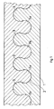
- Fig. 1 zeigt in vergrößerter Darstellung eine Draufsicht auf die Rohraußenwandung 1 eines flexiblen Schaumstoffisolierrohres mit dem in den Rohrmantel eingeschnittenen reißverschlußähnlichen Zahnverschluß 2 mit den ineinandergreifenden Zähnen 3, 3a, die abgerundete Hinterschneidungen aufweisen.
- Fig. 2 und 3 zeigen weitere beispielhafte Ausgestaltungen der Zähne 3, 3a des erfindungsgemäßen reißverschlußähnlichen Zahnverschlusses 2 mit eckigen Hinterschneidungen.
- Der erfindungsgemäße reißverschlußähnliche Zahnverschluß wird vorzugsweise mittels eines Laserstrahls in den Rohrmantel bei der kontinuierlichen Extrusion der Schaumstoffisolierrohre in den Schaumstoffisoliermantel kontinuierlich eingeschnitten. Selbstverständlich kann man aber auch auf bestimmte Längen zugeschnittene Schaumstoffisolierrohre diskontinuierlich mit dem Laserstrahl einschneiden, beispielsweise indem man die Laserstrahlvorrichtung mittels eines Schlittens über das aufzuschlitzende Schaumstoffisolierrohr führt.
- Anstelle der Laserstrahlschlitzung kann man den erfindungsgemäßen reißverschlußähnlichen Zahnverschluß selbstverständlich aber auch durch Stanzen erzeugen.
- Durch die erfindungsgemäß bevorzugten Ausführungsformen der Zähne, insbesondere der Ausführungsform gemäß Fig. 1 und durch das den extrudierten flexiblen Schaumstoffisolierrohren innewohnende Rückstellvermögen kommt es nach Öffnung und Schließung des Zahnverschlusses zu einem engen, spaltlosen Aneinanderliegen der nebeneinander liegenden Zahnflächen, wodurch Luftbrücken zwischen den Zähnen vermieden werden.
- Selbstverständlich kann man den erfindungsgemäßen reißverschlußähnlichen Zahnverschluß nach dem Öffnen auch irreversibel verschließen, indem man entweder nur an die Frontseiten der Zähne oder aber auch von oben an die Seitenflächen der Zähne Klebstoff, insbesondere einen Kontakt Kleber, aufbringt.
Claims (4)
Priority Applications (1)
| Application Number | Priority Date | Filing Date | Title |
|---|---|---|---|
| AT87108899T ATE56082T1 (de) | 1986-06-20 | 1987-06-22 | Schaumstoffisolierrohr aus flexiblem schaumkunststoff mit einem den rohrmantel in richtung der rohrlaengsachse zu oeffnenden verschlusssystem sowie ein verfahren zur herstellung eines solchen verschlusssystems. |
Applications Claiming Priority (2)
| Application Number | Priority Date | Filing Date | Title |
|---|---|---|---|
| DE3620791 | 1986-06-20 | ||
| DE3620791A DE3620791C2 (de) | 1986-06-20 | 1986-06-20 | Schaumstoffisolierrohr aus flexiblem Schaumkunststoff mit einem den Rohrmantel in Richtung der Rohrlängsachse zu öffnenden Verschlußsystem sowie ein Verfahren zur Herstellung eines solchen Verschlußsystems |
Publications (2)
| Publication Number | Publication Date |
|---|---|
| EP0250002A1 EP0250002A1 (de) | 1987-12-23 |
| EP0250002B1 true EP0250002B1 (de) | 1990-08-29 |
Family
ID=6303392
Family Applications (1)
| Application Number | Title | Priority Date | Filing Date |
|---|---|---|---|
| EP87108899A Expired - Lifetime EP0250002B1 (de) | 1986-06-20 | 1987-06-22 | Schaumstoffisolierrohr aus flexiblem Schaumkunststoff mit einem den Rohrmantel in Richtung der Rohrlängsachse zu öffnenden Verschlusssystem sowie ein Verfahren zur Herstellung eines solchen Verschlusssystems |
Country Status (4)
| Country | Link |
|---|---|
| EP (1) | EP0250002B1 (de) |
| AT (1) | ATE56082T1 (de) |
| DE (1) | DE3620791C2 (de) |
| ES (1) | ES2017676B3 (de) |
Families Citing this family (11)
| Publication number | Priority date | Publication date | Assignee | Title |
|---|---|---|---|---|
| FR2641584B1 (fr) * | 1988-01-18 | 1991-05-10 | Caoutchouc Manuf Plastique | Perfectionnement a un dispositif de jonctionnement de panneaux ou de realisation de conduits |
| FR2626046A1 (fr) * | 1988-01-18 | 1989-07-21 | Caoutchouc Manuf Plastique | Dispositif de jonctionnement de panneaux ou de realisation de conduits et ses applications |
| EP0381906B1 (de) * | 1989-01-12 | 1993-02-24 | Caoutchouc Manufacture Et Plastiques | Vorrichtung zur Verbindung von Platten oder der Erstellung von Rohren |
| DE4021746A1 (de) * | 1990-07-07 | 1992-01-16 | Gkn Automotive Ag | Endloser spannring zur befestigung von faltenbaelgen |
| ES2102857T3 (es) * | 1993-06-11 | 1997-08-01 | Minnesota Mining & Mfg | Utensilio de reproduccion maquinado por laser. |
| DE19756047A1 (de) * | 1997-12-17 | 1999-06-24 | Peter Kessler | Stanzwerkzeug zum Anbringen von Gehrungsschnitten in elastisches Material |
| US6162040A (en) * | 1999-02-01 | 2000-12-19 | Velcro Industries B.V. | Molds for forming touch fasteners |
| NL1013414C2 (nl) | 1999-10-28 | 2001-05-02 | Clecon Internat B V | Isolatiemateriaal bestaande uit spandekens te gebruiken voor het isoleren van gebouwen, werkwijze voor het onderling met elkaar verbinden van dergelijk isolatiemateriaal alsmede wand-of dakconstructie voorzien van dergelijk isolatiemateriaal. |
| EP1240972A1 (de) * | 2001-01-17 | 2002-09-18 | Deutsche Rockwool Mineralwoll GmbH & Co. OHG | Verfahren zur Herstellung eines Dämmstoffes |
| WO2007090237A1 (en) * | 2006-02-08 | 2007-08-16 | Five Y's Pty Ltd | Structural member |
| US9669593B2 (en) * | 2007-06-14 | 2017-06-06 | The Boeing Company | Light weight thermoplastic flex foam and hybrid duct system |
Citations (1)
| Publication number | Priority date | Publication date | Assignee | Title |
|---|---|---|---|---|
| DE3332149A1 (de) * | 1983-09-06 | 1985-03-21 | Gert Hauset Noel | Schaumstoffisolierrohr bzw. schaumstoffisolierplatte aus flexiblem schaumkunststoff mit einem in laengsachse angeordneten nut- und federartigen verschlusssystem |
Family Cites Families (5)
| Publication number | Priority date | Publication date | Assignee | Title |
|---|---|---|---|---|
| DE1969408U (de) * | 1967-06-28 | 1967-09-28 | Ernst Fiedler | Umkleidungsmantel fuer rohrleitungen. |
| JPS49129979U (de) * | 1973-03-12 | 1974-11-08 | ||
| JPS5298217A (en) * | 1976-02-13 | 1977-08-17 | Sumitomo Electric Ind Ltd | Thermo-elastic tubular member |
| GB2095615B (en) * | 1981-03-25 | 1984-06-20 | Bingley A J Ltd | Apparatus for cutting and/or welding laminar thermoplastics material |
| AT377310B (de) * | 1983-01-27 | 1985-03-11 | Greiner Kg | Isolierung fuer speicher |
-
1986
- 1986-06-20 DE DE3620791A patent/DE3620791C2/de not_active Revoked
-
1987
- 1987-06-22 EP EP87108899A patent/EP0250002B1/de not_active Expired - Lifetime
- 1987-06-22 ES ES87108899T patent/ES2017676B3/es not_active Expired - Lifetime
- 1987-06-22 AT AT87108899T patent/ATE56082T1/de active
Patent Citations (1)
| Publication number | Priority date | Publication date | Assignee | Title |
|---|---|---|---|---|
| DE3332149A1 (de) * | 1983-09-06 | 1985-03-21 | Gert Hauset Noel | Schaumstoffisolierrohr bzw. schaumstoffisolierplatte aus flexiblem schaumkunststoff mit einem in laengsachse angeordneten nut- und federartigen verschlusssystem |
Also Published As
| Publication number | Publication date |
|---|---|
| ATE56082T1 (de) | 1990-09-15 |
| DE3620791C2 (de) | 1996-01-25 |
| EP0250002A1 (de) | 1987-12-23 |
| DE3620791A1 (de) | 1987-12-23 |
| ES2017676B3 (es) | 1991-03-01 |
Similar Documents
| Publication | Publication Date | Title |
|---|---|---|
| CH663456A5 (de) | Schaumstoffisolierrohr bzw. schaumstoffisolierplatte aus flexiblem schaumkunststoff mit einem in laengsachse angeordneten nut- und federartigen verschlusssystem. | |
| DE69609885T2 (de) | Wärmeschrumpfbare Abschirm-Hülse und Verfahren zu ihrer Herstellung | |
| EP0477484A1 (de) | Kabelführungsrohrbündel und Verfahren zur Herstellung eines Rohraggregates für ein Kabelführungsrohrbündel | |
| DE3048051A1 (de) | Laengsgeteiltes muffenrohr aus thermoplastischem kunststoff mit fomgedaechtnis | |
| DE19519629A1 (de) | Transformator | |
| DE1615602B2 (de) | Elektrische Verbindungsklemme | |
| DE3620791C2 (de) | Schaumstoffisolierrohr aus flexiblem Schaumkunststoff mit einem den Rohrmantel in Richtung der Rohrlängsachse zu öffnenden Verschlußsystem sowie ein Verfahren zur Herstellung eines solchen Verschlußsystems | |
| DE2831029B2 (de) | Kabelmuffe zum Schutz eines Kabelspleißes | |
| EP1909012A2 (de) | Dämm-Manschette | |
| DE3129570C2 (de) | Aufteilungsmuffe | |
| EP0226940B1 (de) | Schrumpfbare Kabelmuffe | |
| DE3400576C2 (de) | Einführungsplatte für Schutzrohre oder dergl. | |
| DE4029929C2 (de) | Sicherheits-Schaltleiste | |
| AT396394B (de) | Rechtwinklig gekruemmte universalisolationshalbschalen fuer rechtwinklige rohrkruemmungen mit unterschiedlichen kruemmungsradien und kruemmungsenden | |
| AT388042B (de) | Schaumstoffisolierrohr bzw. schaumstoffisolierplatte aus flexiblem schaumkunststoff mit einem in laengsachse angeordneten nut- und federartigen verschlusssystem | |
| DE2739214C2 (de) | Dichtungsband zum Abdichten von Kabeleinführungen | |
| EP0374639B1 (de) | Rohraggregat für die Aufname von Kabeln | |
| EP0644367B1 (de) | Formkörper aus Kunststoff für Verbindungs- und Abzweigstellen wärmeisolierter Metallrohre | |
| DE2802470A1 (de) | Verfahren zur herstellung von isolierrohr-formstuecken sowie grundteile derartiger formstuecke | |
| DE3628776A1 (de) | Schutzbeschichtung fuer die mantelflaeche eines rohres und verfahren zur aufbringung einer schutzbeschichtung auf die mantelflaeche eines rohres | |
| DE2909979C2 (de) | Vorrichtung zum Abdichten von Verbindungsstellen an einem durchlaufenden Gegenstand, insbesondere von Kabelmuffen | |
| DE3340851C2 (de) | ||
| DE69501926T2 (de) | Schutzumhüllung für eine Kabeltrommel und Kabeltrommel mit solcher Schutzumhüllung | |
| DE7029076U (de) | Rohrfoermiger einzelkanalabschnitt aus kunststoff mit konstruktiv darauf abgestelltem zusammensteckprofil fuer die fuehrung von luft od. dgl. | |
| CH672364A5 (de) |
Legal Events
| Date | Code | Title | Description |
|---|---|---|---|
| PUAI | Public reference made under article 153(3) epc to a published international application that has entered the european phase |
Free format text: ORIGINAL CODE: 0009012 |
|
| AK | Designated contracting states |
Kind code of ref document: A1 Designated state(s): AT BE CH ES FR GB IT LI NL |
|
| 17P | Request for examination filed |
Effective date: 19880524 |
|
| 17Q | First examination report despatched |
Effective date: 19890328 |
|
| GRAA | (expected) grant |
Free format text: ORIGINAL CODE: 0009210 |
|
| AK | Designated contracting states |
Kind code of ref document: B1 Designated state(s): AT BE CH ES FR GB IT LI NL |
|
| ITF | It: translation for a ep patent filed | ||
| REF | Corresponds to: |
Ref document number: 56082 Country of ref document: AT Date of ref document: 19900915 Kind code of ref document: T |
|
| ET | Fr: translation filed | ||
| GBT | Gb: translation of ep patent filed (gb section 77(6)(a)/1977) | ||
| PG25 | Lapsed in a contracting state [announced via postgrant information from national office to epo] |
Ref country code: AT Effective date: 19910622 |
|
| PLBE | No opposition filed within time limit |
Free format text: ORIGINAL CODE: 0009261 |
|
| STAA | Information on the status of an ep patent application or granted ep patent |
Free format text: STATUS: NO OPPOSITION FILED WITHIN TIME LIMIT |
|
| ITTA | It: last paid annual fee | ||
| 26N | No opposition filed | ||
| PGFP | Annual fee paid to national office [announced via postgrant information from national office to epo] |
Ref country code: CH Payment date: 19960626 Year of fee payment: 10 |
|
| PGFP | Annual fee paid to national office [announced via postgrant information from national office to epo] |
Ref country code: ES Payment date: 19970609 Year of fee payment: 11 |
|
| PGFP | Annual fee paid to national office [announced via postgrant information from national office to epo] |
Ref country code: GB Payment date: 19970619 Year of fee payment: 11 |
|
| PG25 | Lapsed in a contracting state [announced via postgrant information from national office to epo] |
Ref country code: LI Free format text: LAPSE BECAUSE OF NON-PAYMENT OF DUE FEES Effective date: 19970630 Ref country code: CH Free format text: LAPSE BECAUSE OF NON-PAYMENT OF DUE FEES Effective date: 19970630 |
|
| REG | Reference to a national code |
Ref country code: CH Ref legal event code: PL |
|
| PG25 | Lapsed in a contracting state [announced via postgrant information from national office to epo] |
Ref country code: GB Free format text: LAPSE BECAUSE OF NON-PAYMENT OF DUE FEES Effective date: 19980622 |
|
| PG25 | Lapsed in a contracting state [announced via postgrant information from national office to epo] |
Ref country code: ES Free format text: LAPSE BECAUSE OF NON-PAYMENT OF DUE FEES Effective date: 19980623 |
|
| GBPC | Gb: european patent ceased through non-payment of renewal fee |
Effective date: 19980622 |
|
| REG | Reference to a national code |
Ref country code: ES Ref legal event code: FD2A Effective date: 20010503 |
|
| PG25 | Lapsed in a contracting state [announced via postgrant information from national office to epo] |
Ref country code: IT Free format text: LAPSE BECAUSE OF NON-PAYMENT OF DUE FEES;WARNING: LAPSES OF ITALIAN PATENTS WITH EFFECTIVE DATE BEFORE 2007 MAY HAVE OCCURRED AT ANY TIME BEFORE 2007. THE CORRECT EFFECTIVE DATE MAY BE DIFFERENT FROM THE ONE RECORDED. Effective date: 20050622 |
|
| PGFP | Annual fee paid to national office [announced via postgrant information from national office to epo] |
Ref country code: BE Payment date: 20060613 Year of fee payment: 20 |
|
| PGFP | Annual fee paid to national office [announced via postgrant information from national office to epo] |
Ref country code: NL Payment date: 20060616 Year of fee payment: 20 |
|
| PGFP | Annual fee paid to national office [announced via postgrant information from national office to epo] |
Ref country code: FR Payment date: 20060629 Year of fee payment: 20 |
|
| PG25 | Lapsed in a contracting state [announced via postgrant information from national office to epo] |
Ref country code: NL Free format text: LAPSE BECAUSE OF EXPIRATION OF PROTECTION Effective date: 20070622 |
|
| NLV7 | Nl: ceased due to reaching the maximum lifetime of a patent |
Effective date: 20070622 |
|
| BE20 | Be: patent expired |
Owner name: S.A. NOEL *MARQUET & CIE Effective date: 20070622 |