EP0249907A2 - Housing system for electrical apparatuses - Google Patents
Housing system for electrical apparatuses Download PDFInfo
- Publication number
- EP0249907A2 EP0249907A2 EP87108520A EP87108520A EP0249907A2 EP 0249907 A2 EP0249907 A2 EP 0249907A2 EP 87108520 A EP87108520 A EP 87108520A EP 87108520 A EP87108520 A EP 87108520A EP 0249907 A2 EP0249907 A2 EP 0249907A2
- Authority
- EP
- European Patent Office
- Prior art keywords
- housing part
- upper housing
- plug
- housing
- socket
- Prior art date
- Legal status (The legal status is an assumption and is not a legal conclusion. Google has not performed a legal analysis and makes no representation as to the accuracy of the status listed.)
- Granted
Links
Images

Classifications
-
- H—ELECTRICITY
- H01—ELECTRIC ELEMENTS
- H01R—ELECTRICALLY-CONDUCTIVE CONNECTIONS; STRUCTURAL ASSOCIATIONS OF A PLURALITY OF MUTUALLY-INSULATED ELECTRICAL CONNECTING ELEMENTS; COUPLING DEVICES; CURRENT COLLECTORS
- H01R29/00—Coupling parts for selective co-operation with a counterpart in different ways to establish different circuits, e.g. for voltage selection, for series-parallel selection, programmable connectors
Definitions
- the invention relates to a housing system for electrical devices, with a plug and a socket and a control or switching arrangement between the socket and plug.
- Such devices have been known for a long time and are mainly sold in their design as so-called socket time switches. Such devices are so-called mono products, that is, they are designed as a whole for the corresponding application and the relevant product design. In the meantime, however, a need for a wide variety of consumer devices has emerged on the market, in which it is important to switch any electrical consumers depending on external circumstances.
- the housing system from a lower housing part with a plug, a first upper housing part with a socket and a second upper housing part with the control or switching arrangement, and the two housing parts to be placed next to each other on the lower housing part and to be fastened there.
- the housing system thus consists of 3 modules, of which the module forming the second housing upper part is constant in length and width, but has different control or switching arrangements in its interior. Depending on these, its height may change.
- control or switching arrangements moisture detectors, RCCBs, voltage and interference protection switches, random generators for controlling lamps, acoustic switches for room monitoring, synchronous time switches and finally time switches of various designs are provided.
- the housing system according to the invention also allows a splash-proof version to be built up in a simple manner instead of standard versions.
- the first upper housing part 1 with a socket 2 and the second upper housing part 3, which has a control or switching arrangement. In the present case, this is an electronic random number generator.
- the lower part 4 of the housing on the underside of which a plug 5 is arranged exactly under the socket 2.
- the socket and the plug are arranged interchangeably in the upper housing part and in the lower housing part and can be exchanged for plug systems, as are required in other countries.
- the second embodiment of the invention shows a splash-proof embodiment.
- the device is constructed in the same way as that according to Figure 1, but the first housing upper part 1 is replaced by a housing upper part 6, in which a cover 7 covers the socket 2 and protects against splashing water.
- Figure 5 shows in a section the basic structure of the housing system, whereby for the sake of clarity the socket and the plug, since components known per se are omitted. It is an arrangement according to the first embodiment.
- the first upper housing part 1 is placed on the lower housing part 4 in such a way that the socket and the plug lie on a common axis 8.
- the upper part is provided with a spring 9 which engages in a groove 10 of the lower part.
- the attachment is carried out by means of pillars 11a and 11b formed on the upper part and pillars 12a and 12b formed on the lower part. All pillars are hollow and are connected from below by screws, not shown.
- the second upper housing part 3 is fastened on one side with a pillar 13 on a pillar 14 of the lower housing part. On its right side in the drawing, it engages with a laterally molded part 15 and a groove 16 under the first upper housing part 1 and is fixed by the latter.
- the second upper housing part 3 also rests with a spring 9 in a groove 10 in the lower housing part in accordance with FIG. 5a.
- electrical lines 20 also leave the printed circuit board 18, which are held separately from one another by webs 21 and - in a manner not shown - lead into the area of the plug and the socket .
- the arrangement of the webs 21 can be seen even more clearly in Figure 6, as can the circumferential groove 10 in the lower housing part 4.
- FIG. 6a Detail B is shown enlarged in Figure 6a
- Figure 6b shows a view of detail B in the direction of arrow C.
- the circumferential groove 10 of the lower housing part 4 and a recess 22 into which the first upper housing part 1 and the second upper housing part 3 are each inserted from above can be seen.
- the upper housing part 1 then lies in the groove 16 on the upper housing part 3 (see Figure 5).
Landscapes
- Casings For Electric Apparatus (AREA)
Abstract
Die Erfindung bezieht sich auf ein Gehäusesystem für elektrische Geräte, insbesondere Konsumgeräte, welche zur Steuerung von elektrischen Verbrauchern dienen und eine Steckdose (2) und einen Stecker (5) aufweisen. Das Gehäusesystem besteht aus einem Gehäuseunterteil (4) mit dem Stecker (5), einem ersten Gehäuseoberteil (1) mit der Steckdose (2) sowie einem zweiten Gehäuseoberteil (3), welches wahlweise verschiedene Steuer- und Schaltanordnungen (19) enthalten kann. Alle Gehäuseteile werden zusammengesteckt und dann verschraubt.The invention relates to a housing system for electrical devices, in particular consumer devices, which are used to control electrical consumers and have a socket (2) and a plug (5). The housing system consists of a lower housing part (4) with the plug (5), a first upper housing part (1) with the socket (2) and a second upper housing part (3), which can optionally contain various control and switching arrangements (19). All housing parts are put together and then screwed together.
Description
Die Erfindung bezieht sich auf ein Gehäusesystem für elektrische Geräte, mit einem Stecker und einer Steckdose sowie einer Steuer- oder Schaltanordnung zwischen Steckdose und Stecker.The invention relates to a housing system for electrical devices, with a plug and a socket and a control or switching arrangement between the socket and plug.
Derartige Geräte sind bereits seit längerem bekannt und werden vor allem in ihrer Ausgestaltung als sogenannte Steckdosen-Schaltuhren vertrieben. Solche Geräte sind sogenannte Monoprodukte, das heißt, sie sind als Ganzes für den entsprechenden Anwendungszweck und die betreffende Produktausgestaltung konstruiert. Zwischenzeitlich hat sich jedoch am Markt ein Bedarf verschiedenster Konsumgeräte herausgebildet, bei denen es darauf ankommt, irgendwelche elektrischen Verbraucher abhängig von äußeren Gegebenheiten zu schalten.Such devices have been known for a long time and are mainly sold in their design as so-called socket time switches. Such devices are so-called mono products, that is, they are designed as a whole for the corresponding application and the relevant product design. In the meantime, however, a need for a wide variety of consumer devices has emerged on the market, in which it is important to switch any electrical consumers depending on external circumstances.
Es ist nun Aufgabe der Erfindung, ein Gehäusesystem anzugeben, welches aus verschiedenen Standardmodulen aufgebaut ist und sich in einfacher Weise den verschiedenen Geräteanforderungen anpassen läßt.It is an object of the invention to provide a housing system which is constructed from various standard modules and can be easily adapted to the various device requirements.
Zur Lösung dieser Aufgabe wird vorgeschlagen, das Gehäusesystem aus einem Gehäuseunterteil mit Stecker, einem ersten Gehäuseoberteil mit Steckdose und einem zweiten Gehäuseoberteil mit der Steuer- oder Schaltanordnung aufzubauen und die beiden Gehäuseteile nebeneinander auf das Gehäuseunterteil aufsteckbar und dort befestigbar auszugestalten.To solve this problem, it is proposed to construct the housing system from a lower housing part with a plug, a first upper housing part with a socket and a second upper housing part with the control or switching arrangement, and the two housing parts to be placed next to each other on the lower housing part and to be fastened there.
Das Gehäusesystem besteht damit aus 3 Modulen, von welchen der das zweite Gehäuseoberteil bildende Modul in seiner Länge und Breite konstant ist,in seinem inneren jedoch verschiedene Steuer- oder Schaltanordnungen aufweist. Abhängig von diesen ändert sich dabei gegebenenfalls seine Höhe. Als Ausgestaltungsmöglichkeiten für die Steuer- oder Schaltanordnungen sind Feuchtemelder, FI-Schutzschalter, Spannungs- und Störschutzschalter, Zufallsgeneratoren für die Steuerung von Lampen, akustische Schalter zur Raumüberwachung, Synchronzeitschalter und schließlich auch Schaltuhren verschiedenster Ausgestaltung vorgesehen.The housing system thus consists of 3 modules, of which the module forming the second housing upper part is constant in length and width, but has different control or switching arrangements in its interior. Depending on these, its height may change. As design options for the control or switching arrangements, moisture detectors, RCCBs, voltage and interference protection switches, random generators for controlling lamps, acoustic switches for room monitoring, synchronous time switches and finally time switches of various designs are provided.
Das erfindungsgemäße Gehäusesystem erlaubt auch in einfacher Weise anstelle von Standardausführungen solche in spritzwassergeschützte Ausführung aufzubauen.The housing system according to the invention also allows a splash-proof version to be built up in a simple manner instead of standard versions.
Im Folgenden soll die Erfindung an mehreren Ausführungsbeispielen anhand der Zeichnung noch näher erläutert werden.In the following, the invention will be explained in more detail using several exemplary embodiments with reference to the drawing.
Es zeigen:
Abbildung 1 ein erstes Ausführungsbeispiel in Standardausführung in einer Ansicht von oben;Abbildung 2 das erste Ausführungsbeispiel in einer Ansicht von der Seite;Abbildung 3 ein zweites Ausführungsbeispiel einer spritzwassergeschützten Ausführung in einer Ansicht von oben;Abbildung 4 das zweite Ausführungsbeispiel in einer Ansicht von der Seite;Abbildung 5 einen Schnitt durch das Ausführungsbeispiel gemäßAbbildung 1 ohne Stecker und Steckdose;- Abbildung 5a eine Einzelheit aus
Abbildung 5; Abbildung 6 eine Draufsicht der Anordnung nachAbbildung 5;- Abbildung 6a eine erste Einzelheite aus
Abbildung 6; - Abbildung 6b eine zweite Einzelheit aus
Abbildung 6.
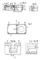
- Figure 1 shows a first embodiment in standard execution in a view from above;
- Figure 2 shows the first embodiment in a side view;
- Figure 3 shows a second embodiment of a splash-proof version in a view from above;
- Figure 4 shows the second embodiment in a side view;
- Figure 5 shows a section through the embodiment of Figure 1 without a plug and socket;
- Figure 5a is a detail from Figure 5;
- Figure 6 is a top view of the arrangement of Figure 5;
- Figure 6a a first detail from Figure 6;
- Figure 6b shows a second detail from Figure 6.
In den Abbildungen 1 und 2 sieht man bei dem ersten Ausführungsbeispiel der Erfindung das erste Gehäuseoberteil 1 mit einer Steckdose 2 und das zweite Gehäuseoberteil 3, welches eine Steuer- oder Schaltanordnung aufweist. Im vorliegenden Fall ist dies ein elektronischer Zufallsgenerator. In Abbildung 2 erkennt man das Gehäuseunterteil 4, an dessen Unterseite, genau unter der Steckdose 2,ein Stecker 5 angeordnet ist. Die Steckdose und der Stecker sind in dem Gehäuseoberteil bzw. in dem Gehäuseunterteil auswechselbar angeordnet und können gegen Steckersysteme, wie sie in anderen Ländern erforderlich sind, ausgetauscht werden.In Figures 1 and 2 you can see in the first embodiment of the invention, the first
Das zweite Ausführungsbeispiel der Erfindung zeigt eine spritzwassergeschützte Ausführungsform. Das Gerät ist in gleicher Weise aufgebaut wie jenes nach Abbildung 1, jedoch ist das erste Gehäuseoberteil 1 durch ein Gehäuseoberteil 6 ersetzt, bei welchem ein Deckel 7 die Steckdose 2 abdeckt und gegen Spritzwasser schützt.The second embodiment of the invention shows a splash-proof embodiment. The device is constructed in the same way as that according to Figure 1, but the first housing
In Abbildung 5 erkennt man in einem Schnitt den grundsätzlichen Aufbau des Gehäusesystems, wobei der Übersichtlichkeit halber die Steckdose und der Stecker, da an sich bekannte Bauteile, weggelassen sind. Es handelt sich dabei um eine Anordnung gemäß dem ersten Ausführungsbeispiel. Das erste Gehäuseoberteil 1 ist so auf das Gehäuseunterteil 4 aufgesetzt, daß Steckdose und Stecker auf einer gemeinsamen Achse 8 liegen. Das Oberteil ist mit einer Feder 9 versehen, welche in eine Nut 10 des Unterteils eingreift. Die Befestigung erfolgt durch an dem Oberteil angeformte Pfeiler 11a und 11b in an dem Unterteil angeformte Pfeiler 12a und 12b. Alle Pfeiler sind hohl und werden von unten durch nicht dargestellte Schrauben miteinander verbunden.Figure 5 shows in a section the basic structure of the housing system, whereby for the sake of clarity the socket and the plug, since components known per se are omitted. It is an arrangement according to the first embodiment. The first
Das zweite Gehäuseoberteil 3 ist mit einem Pfeiler 13 auf einem Pfeiler 14 des Gehäuseunterteils an der einen Seite befestigt. An seiner in der Zeichnung rechten Seite greift es mit einem seitlich angespritzten Teil 15 und einer Nut 16 unter das erste Gehäuseoberteil 1 und wird von diesem festgelegt. Auch das zweite Gehäuseoberteil 3 ruht mit einer Feder 9 in einer Nut 10 des Gehäuseunterteils entsprechend Abbildung 5a. An dem zweiten Gehäuseoberteil 3 sind ferner Pfeiler 17a und 17b angeordnet, welche eine Leiterplatte 18 mit elektrischen Bauteilen 19 tragen. Diese Bauteile 19 stellen den die Steuer- oder Schaltanordnung bildenden Zufallsgenerator dar. Von der Leiterplatte 18 gehen schließlich noch elektrische Leitungen 20 ab, welche von Stegen 21 voneinander getrennt gehaltert werden und - in nicht dargestellter Weise - in den Bereich des Steckers und der Steckdose führen. Die Anordnung der Stege 21 ist in Abbildung 6 noch deutlicher zu sehen, ebenso die umlaufende Nut 10 im Gehäuseunterteil 4.The second
Das Detail B ist in Abbildung 6a vergrößert dargestellt, Abbildung 6b stellt eine Ansicht des Details B in Pfeilrichtung C dar. Man erkennt die umlaufende Nut 10 des Gehäuseunterteiles 4 und eine Ausnehmung 22, in welche das erste Gehäuseoberteil 1 und das zweite Gehäuseoberteil 3 jeweils von oben eingesetzt werden. Dabei kommt dann das Gehäuseoberteil 1 in die Nut 16 am Gehäuseoberteil 3 (siehe Abbildung 5) zu liegen.Detail B is shown enlarged in Figure 6a, Figure 6b shows a view of detail B in the direction of arrow C. The
Claims (9)
dadurch gekennzeichnet,
daß das Gehäusesystem aus einem Gehäuseunterteil (4) mit Stecker (5), einem ersten Gehäuseoberteil (1) mit Steckdose (2) und einem zweiten Gehäuseoberteil (3) mit der Steuer- oder Schaltanordnung (19) besteht und daß die beiden Gehäuseoberteile (1, 3) nebeneinander auf das Gehäuseunterteil (4) aufgesteckt und befestigt sind.1. Housing system for electrical devices with a plug and a socket, and a control or switching arrangement between socket (input) and plug (output),
characterized,
that the housing system consists of a lower housing part (4) with plug (5), a first upper housing part (1) with socket (2) and a second upper housing part (3) with the control or switching arrangement (19) and that the two upper housing parts (1 , 3) are placed next to each other on the lower housing part (4) and fastened.
dadurch gekennzeichnet,
daß das erste Gehäuseoberteil (1) auf den Bereich des Gehäuseunterteils (4) mit dem Stecker (5) aufgesetzt und das zweite Gehäuseoberteil (3) auf den anderen Bereich des Gehäuseunterteils aufgesteckt ist.2. Housing system according to claim 1,
characterized,
that the first upper housing part (1) is placed on the area of the lower housing part (4) with the plug (5) and the second upper housing part (3) is placed on the other area of the lower housing part.
dadurch gekennzeichnet,
daß das zweite Gehäuseoberteil (3) als voll gekapselter Modul ausgebildet ist, aus welchem in das Gehäuseunterteil nur die elektrischen Versorgungs- und Steuerleitungen (20) ragen.3. Housing system according to claim 1 or 2,
characterized,
that the second upper housing part (3) is designed as a fully encapsulated module, from which only the electrical supply and control lines (20) protrude into the lower housing part.
dadurch gekennzeichnet,
daß das zweite Gehäuseoberteil (3) nach innen offen ist und mit seinen elektrischen Bauteilen sowie den elektrischen Versorgungs- und Steuerleitungen (20) in das Gehäuseunterteil (4) ragt.4. Housing system according to claim 1 or 2,
characterized,
that the second upper housing part (3) open to the inside and with its electrical components and the electrical supply and control lines (20) protrudes into the lower housing part (4).
dadurch gekennzeichnet,
daß der Stecker (5) und die Steckdose (2) in ihren Gehäuseteilen (1, 4) auswechselbar und den elektrischen Anforderungen in den verschiedenen Ländern anpaßbar sind.5. Housing system according to one or more of claims 1 to 4,
characterized,
that the plug (5) and the socket (2) in their housing parts (1, 4) are interchangeable and adaptable to the electrical requirements in the different countries.
dadurch gekennzeichnet,
daß das Gehäuseunterteil (4) eine umlaufende Nut (10) und die Gehäuseoberteile (1, 3) eine umlaufende Feder (9) bestizen, mit welchen Elementen die Gehäuseteile (1, 3, 4) zusammengesteckt werden können.6. Housing system according to one or more of claims 1 to 5,
characterized,
that the lower housing part (4) have a circumferential groove (10) and the upper housing parts (1, 3) have a circumferential spring (9) with which elements the housing parts (1, 3, 4) can be plugged together.
dadurch gekennzeichnet,
daß das zweite Gehäuseoberteil (3) an seiner dem ersten Gehäuseoberteil (1) im montierten Zustand zugewandten Seite eine außenliegende Nut (16) aufweist, in welche die entsprechende Unterkante des ersten Gehäuseoberteils (1) eingreift.7. Housing system according to claim 6,
characterized,
that the second upper housing part (3) on its side facing the first upper housing part (1) in the assembled state has an external groove (16) into which the corresponding lower edge of the first upper housing part (1) engages.
dadurch gekennzeichnet,
daß das erste Gehäuseoberteil (1) einen Deckel (7) für Spritzwasserschutz besitzt.8. Housing system according to one or more of claims 1 to 7,
characterized,
that the first upper housing part (1) has a cover (7) for splash water protection.
dadurch gekennzeichnet,
daß im Gehäuseunterteil (4) im Bereich zwischen dem ersten und dem zweiten Gehäuseoberteil Stege (21) angebracht sind, zwischen denen die elektrischen Verbindungselemente (20) wie Drähte oder Steckelemente voneinander getrennt werden.9. Housing system according to claim 2,
characterized,
that in the lower housing part (4) in the region between the first and the second upper housing part webs (21) are attached, between which the electrical connecting elements (20) such as wires or plug elements are separated from one another.
Applications Claiming Priority (2)
| Application Number | Priority Date | Filing Date | Title |
|---|---|---|---|
| DE3620698 | 1986-06-20 | ||
| DE19863620698 DE3620698A1 (en) | 1986-06-20 | 1986-06-20 | HOUSING SYSTEM FOR ELECTRICAL DEVICES |
Publications (3)
| Publication Number | Publication Date |
|---|---|
| EP0249907A2 true EP0249907A2 (en) | 1987-12-23 |
| EP0249907A3 EP0249907A3 (en) | 1989-07-26 |
| EP0249907B1 EP0249907B1 (en) | 1993-09-08 |
Family
ID=6303333
Family Applications (1)
| Application Number | Title | Priority Date | Filing Date |
|---|---|---|---|
| EP87108520A Expired - Lifetime EP0249907B1 (en) | 1986-06-20 | 1987-06-12 | Housing system for electrical apparatuses |
Country Status (2)
| Country | Link |
|---|---|
| EP (1) | EP0249907B1 (en) |
| DE (2) | DE3620698A1 (en) |
Cited By (3)
| Publication number | Priority date | Publication date | Assignee | Title |
|---|---|---|---|---|
| EP0402654A3 (en) * | 1989-06-10 | 1991-04-17 | Gebrüder Merten Gmbh & Co. Kg | Connection device for the connection of electrical appliances |
| WO1991015041A1 (en) * | 1990-03-19 | 1991-10-03 | Grässlin KG | Electrical connection device for plug-in switch clocks |
| EP1280244A1 (en) * | 2001-07-13 | 2003-01-29 | ABB Schweiz AG | Mobile plugable apparatus system |
Families Citing this family (3)
| Publication number | Priority date | Publication date | Assignee | Title |
|---|---|---|---|---|
| DE4331187C2 (en) * | 1993-09-14 | 1998-04-09 | Siemens Ag | Electric battery charger |
| DE19734584B4 (en) * | 1997-08-09 | 2006-04-20 | Insta Elektro Gmbh | Two-piece distributor housing for electrotechnical installations |
| DE102016112651A1 (en) * | 2016-07-11 | 2018-01-11 | Denqbar Holding GmbH | Socket for use in mobile devices for differently standardized connectors |
Family Cites Families (4)
| Publication number | Priority date | Publication date | Assignee | Title |
|---|---|---|---|---|
| DE2546277B2 (en) * | 1975-10-16 | 1980-05-14 | Brown, Boveri & Cie Ag, 6800 Mannheim | Device with a plug part, a socket-like connection part and with a control part or a coupling socket |
| DE2908597A1 (en) * | 1979-03-05 | 1980-09-25 | Westdeutsche Elektrogeraete | ELECTRICAL PLUG DEVICE WITH PLUG, SOCKET, AND ELECTRICAL DEVICE FOR THE OPERATION OF AN ACTUATOR AND / OR SWITCHING AND / OR DISPLAY DEVICE |
| DE3004271C2 (en) * | 1980-02-06 | 1984-10-11 | Büchele, Karl, 8000 München | Housing composed of modular elements |
| DE8403456U1 (en) * | 1984-02-07 | 1985-06-05 | Diehl GmbH & Co, 8500 Nürnberg | Socket timer |
-
1986
- 1986-06-20 DE DE19863620698 patent/DE3620698A1/en active Granted
-
1987
- 1987-06-12 DE DE87108520T patent/DE3787323D1/en not_active Expired - Fee Related
- 1987-06-12 EP EP87108520A patent/EP0249907B1/en not_active Expired - Lifetime
Cited By (3)
| Publication number | Priority date | Publication date | Assignee | Title |
|---|---|---|---|---|
| EP0402654A3 (en) * | 1989-06-10 | 1991-04-17 | Gebrüder Merten Gmbh & Co. Kg | Connection device for the connection of electrical appliances |
| WO1991015041A1 (en) * | 1990-03-19 | 1991-10-03 | Grässlin KG | Electrical connection device for plug-in switch clocks |
| EP1280244A1 (en) * | 2001-07-13 | 2003-01-29 | ABB Schweiz AG | Mobile plugable apparatus system |
Also Published As
| Publication number | Publication date |
|---|---|
| EP0249907A3 (en) | 1989-07-26 |
| EP0249907B1 (en) | 1993-09-08 |
| DE3787323D1 (en) | 1993-10-14 |
| DE3620698A1 (en) | 1987-12-23 |
| DE3620698C2 (en) | 1990-06-07 |
Similar Documents
| Publication | Publication Date | Title |
|---|---|---|
| EP0161434B1 (en) | Electric, in particular an electronic switching apparatus working without making contact | |
| DE4419895A1 (en) | Connecting arrangement in a prefabricated cable harness for vehicles | |
| DE29607525U1 (en) | Modular, modularly expandable peripheral device with self-establishing electrical connection | |
| EP0739156B1 (en) | Encapsulated input/output assembly | |
| EP0712267A2 (en) | Modular control equipment with field bus integrated connection | |
| DE2724939C3 (en) | Switching device, in particular electronic, contactless switching device | |
| EP1239214A2 (en) | Pillar-shaped indicator lamp | |
| DE102012102884B4 (en) | Power supply module for a linear actuator and conversion group for this purpose | |
| DE3620698C2 (en) | ||
| DE3943752C2 (en) | Pneumatic or hydraulic valve unit | |
| DE69111057T2 (en) | ELECTRICAL CONNECTING DEVICE FOR CONTROL VALVES IN A VALVE ARRANGEMENT. | |
| DE8616495U1 (en) | Housing system for electrical devices | |
| DE1286165C2 (en) | Printed circuit board with shield | |
| DE10127595A1 (en) | Circuit arrangement for several sensor elements | |
| DE2340773A1 (en) | Transfer plug connector for wiring system with spring strip - has terminal pins protruding above wiring plane for connection to respective cct. boards | |
| DE2355924A1 (en) | LOGICAL UNIT FOR USE IN LOGICAL CIRCUITS FOR INDUSTRIAL APPLICATIONS | |
| EP1041470A2 (en) | Electronic timing switch for cooker | |
| EP0670033B1 (en) | Circuitry for processing analogical current and voltage signals | |
| DE29822203U1 (en) | Installation block for a cable junction box | |
| DE2061428A1 (en) | Storage for a three-layer circuit | |
| DE19738736A1 (en) | Contact sensor | |
| EP0866524B1 (en) | Installation for connecting external lines to an automation device | |
| CH411069A (en) | Housing to accommodate a printed circuit board | |
| DE2460379C2 (en) | Plastic-encapsulated semiconductor arrangement in the form of a pin diode II element | |
| DE3119397A1 (en) | Housing for electrical and/or electronic components |
Legal Events
| Date | Code | Title | Description |
|---|---|---|---|
| PUAI | Public reference made under article 153(3) epc to a published international application that has entered the european phase |
Free format text: ORIGINAL CODE: 0009012 |
|
| AK | Designated contracting states |
Kind code of ref document: A2 Designated state(s): DE FR GB SE |
|
| PUAL | Search report despatched |
Free format text: ORIGINAL CODE: 0009013 |
|
| AK | Designated contracting states |
Kind code of ref document: A3 Designated state(s): DE FR GB SE |
|
| 17P | Request for examination filed |
Effective date: 19890616 |
|
| 17Q | First examination report despatched |
Effective date: 19910911 |
|
| GRAA | (expected) grant |
Free format text: ORIGINAL CODE: 0009210 |
|
| AK | Designated contracting states |
Kind code of ref document: B1 Designated state(s): DE FR GB SE |
|
| REF | Corresponds to: |
Ref document number: 3787323 Country of ref document: DE Date of ref document: 19931014 |
|
| ET | Fr: translation filed | ||
| GBT | Gb: translation of ep patent filed (gb section 77(6)(a)/1977) |
Effective date: 19940119 |
|
| PLBE | No opposition filed within time limit |
Free format text: ORIGINAL CODE: 0009261 |
|
| STAA | Information on the status of an ep patent application or granted ep patent |
Free format text: STATUS: NO OPPOSITION FILED WITHIN TIME LIMIT |
|
| 26N | No opposition filed | ||
| EAL | Se: european patent in force in sweden |
Ref document number: 87108520.5 |
|
| PGFP | Annual fee paid to national office [announced via postgrant information from national office to epo] |
Ref country code: FR Payment date: 19960426 Year of fee payment: 10 |
|
| PGFP | Annual fee paid to national office [announced via postgrant information from national office to epo] |
Ref country code: GB Payment date: 19960607 Year of fee payment: 10 |
|
| PGFP | Annual fee paid to national office [announced via postgrant information from national office to epo] |
Ref country code: SE Payment date: 19960626 Year of fee payment: 10 |
|
| PGFP | Annual fee paid to national office [announced via postgrant information from national office to epo] |
Ref country code: DE Payment date: 19960817 Year of fee payment: 10 |
|
| PG25 | Lapsed in a contracting state [announced via postgrant information from national office to epo] |
Ref country code: GB Free format text: LAPSE BECAUSE OF NON-PAYMENT OF DUE FEES Effective date: 19970612 |
|
| PG25 | Lapsed in a contracting state [announced via postgrant information from national office to epo] |
Ref country code: SE Effective date: 19970613 |
|
| GBPC | Gb: european patent ceased through non-payment of renewal fee |
Effective date: 19970612 |
|
| PG25 | Lapsed in a contracting state [announced via postgrant information from national office to epo] |
Ref country code: FR Free format text: LAPSE BECAUSE OF NON-PAYMENT OF DUE FEES Effective date: 19980227 |
|
| EUG | Se: european patent has lapsed |
Ref document number: 87108520.5 |
|
| PG25 | Lapsed in a contracting state [announced via postgrant information from national office to epo] |
Ref country code: DE Free format text: LAPSE BECAUSE OF NON-PAYMENT OF DUE FEES Effective date: 19980303 |
|
| REG | Reference to a national code |
Ref country code: FR Ref legal event code: ST |
|
| REG | Reference to a national code |
Ref country code: FR Ref legal event code: ST |