EP0249816B1 - Improved railway train of highway vehicles and components therefor - Google Patents
Improved railway train of highway vehicles and components therefor Download PDFInfo
- Publication number
- EP0249816B1 EP0249816B1 EP87108093A EP87108093A EP0249816B1 EP 0249816 B1 EP0249816 B1 EP 0249816B1 EP 87108093 A EP87108093 A EP 87108093A EP 87108093 A EP87108093 A EP 87108093A EP 0249816 B1 EP0249816 B1 EP 0249816B1
- Authority
- EP
- European Patent Office
- Prior art keywords
- trailer
- set forth
- railway train
- air
- assembly
- Prior art date
- Legal status (The legal status is an assumption and is not a legal conclusion. Google has not performed a legal analysis and makes no representation as to the accuracy of the status listed.)
- Expired - Lifetime
Links
Images


Classifications
-
- B—PERFORMING OPERATIONS; TRANSPORTING
- B60—VEHICLES IN GENERAL
- B60G—VEHICLE SUSPENSION ARRANGEMENTS
- B60G5/00—Resilient suspensions for a set of tandem wheels or axles having interrelated movements
- B60G5/02—Resilient suspensions for a set of tandem wheels or axles having interrelated movements mounted on a single pivoted arm, e.g. the arm being rigid
-
- B—PERFORMING OPERATIONS; TRANSPORTING
- B60—VEHICLES IN GENERAL
- B60F—VEHICLES FOR USE BOTH ON RAIL AND ON ROAD; AMPHIBIOUS OR LIKE VEHICLES; CONVERTIBLE VEHICLES
- B60F1/00—Vehicles for use both on rail and on road; Conversions therefor
- B60F1/04—Vehicles for use both on rail and on road; Conversions therefor with rail and road wheels on different axles
- B60F1/046—Semi-trailer or trailer type vehicles without own propelling units
-
- B—PERFORMING OPERATIONS; TRANSPORTING
- B61—RAILWAYS
- B61D—BODY DETAILS OR KINDS OF RAILWAY VEHICLES
- B61D3/00—Wagons or vans
- B61D3/10—Articulated vehicles
- B61D3/12—Articulated vehicles comprising running gear interconnected by loads
-
- B—PERFORMING OPERATIONS; TRANSPORTING
- B61—RAILWAYS
- B61D—BODY DETAILS OR KINDS OF RAILWAY VEHICLES
- B61D3/00—Wagons or vans
- B61D3/16—Wagons or vans adapted for carrying special loads
- B61D3/18—Wagons or vans adapted for carrying special loads for vehicles
- B61D3/182—Wagons or vans adapted for carrying special loads for vehicles specially adapted for heavy vehicles, e.g. public work vehicles, trucks, trailers
- B61D3/184—Wagons or vans adapted for carrying special loads for vehicles specially adapted for heavy vehicles, e.g. public work vehicles, trucks, trailers the heavy vehicles being of the trailer or semi-trailer type
-
- B—PERFORMING OPERATIONS; TRANSPORTING
- B61—RAILWAYS
- B61F—RAIL VEHICLE SUSPENSIONS, e.g. UNDERFRAMES, BOGIES OR ARRANGEMENTS OF WHEEL AXLES; RAIL VEHICLES FOR USE ON TRACKS OF DIFFERENT WIDTH; PREVENTING DERAILING OF RAIL VEHICLES; WHEEL GUARDS, OBSTRUCTION REMOVERS OR THE LIKE FOR RAIL VEHICLES
- B61F3/00—Types of bogies
- B61F3/12—Types of bogies specially modified for carrying adjacent vehicle bodies of articulated trains
- B61F3/125—Types of bogies specially modified for carrying adjacent vehicle bodies of articulated trains with more than one axle or wheel set
-
- B—PERFORMING OPERATIONS; TRANSPORTING
- B61—RAILWAYS
- B61F—RAIL VEHICLE SUSPENSIONS, e.g. UNDERFRAMES, BOGIES OR ARRANGEMENTS OF WHEEL AXLES; RAIL VEHICLES FOR USE ON TRACKS OF DIFFERENT WIDTH; PREVENTING DERAILING OF RAIL VEHICLES; WHEEL GUARDS, OBSTRUCTION REMOVERS OR THE LIKE FOR RAIL VEHICLES
- B61F5/00—Constructional details of bogies; Connections between bogies and vehicle underframes; Arrangements or devices for adjusting or allowing self-adjustment of wheel axles or bogies when rounding curves
- B61F5/02—Arrangements permitting limited transverse relative movements between vehicle underframe or bolster and bogie; Connections between underframes and bogies
- B61F5/16—Centre bearings or other swivel connections between underframes and bolsters or bogies
-
- B—PERFORMING OPERATIONS; TRANSPORTING
- B61—RAILWAYS
- B61G—COUPLINGS; DRAUGHT AND BUFFING APPLIANCES
- B61G5/00—Couplings for special purposes not otherwise provided for
- B61G5/02—Couplings for special purposes not otherwise provided for for coupling articulated trains, locomotives and tenders or the bogies of a vehicle; Coupling by means of a single coupling bar; Couplings preventing or limiting relative lateral movement of vehicles
Definitions
- the present invention relates generally to an improved railway train of highway trailers including leading and following trailers which are connected to each other, adjacent ends of said highway trailers being supported solely by railtruck assemblies, each of said highway trailers including a body, a forwardly extending load supporting tongue which also withstands the push and pull (buff and draft) forces between interconnected trailers, rear tongue coupling means which receives and is removably coupled to the forward end of the forwardly extending tongue of an adjacent highway trailer, and rear receiving means which receives and is removably coupled to the supporting railtrucks assembly, and each of the railtruck assemblies including an intermodal adapter being provided with at least one first locating portion and at least one first coupling means, the first locating portion being received within said rear receiving means and being coupled thereto by said first coupling means, and a conventional railtruck having longitudinally extending side frames and a centrally-located transversely extending bolster supported on said side frames, the intermodal adapter being supported on said bolster for limited rotational movement about a generally vertically extending
- each railtruck assembly can be in turn coupled to a receiving portion of a leading trailer. While that adapter performs in a satisfactory manner, it has the disadvantage in being unidirectional.
- the manually operated screw jack utilized in the prior design to shift the coupler pin may not be suitable for use when the train is under heavy tension or compression, due to steep grades or long train consists.
- EP-A-0 143 614 discloses a road/rail transport system comprising a rail bogie of the kind having two axles and a central bogie bolster arranged between the axles and transverse to the intended direction of travel of the bogie.
- the bolster has a pocket and a mounting member held in the pocket, the pocket and mounting member having complementary surfaces, preferably part spherical surfaces, in engagement so as to permit limited movement of the mounting member relative to the pocket.
- the mounting member is adapted for releasable attachment to the frame of a transporter body.
- US-A-2 036 535 discloses a railtruck assembly comprising an adapter frame having guide plates symmetrically arranged on the truck and receiving a central pin provided at the ends of trailers to be coupled, and coupling means also symmetrically arranged.
- This symmetrical arrangement employs two bolsters which are spaced apart and located above each of the two axles for the two wheel sets.
- the object of the invention is to provide a railtruck assembly which can be coupled to a leading trailer, the railtruck assembly being bi-directional so that it can be coupled to a leading trailer disposed to either side of the bolster of the railtruck assembly.
- railway train of highway trailers including leading and following trailers which are connected to each other, adjacent ends of said highway trailers being supported solely by railtruck assemblies, each of said highway trailers including a body, a forwardly extending load supporting tongue which also withstands the push and pull (buff and draft) forces between interconnected trailers, rear tongue coupling means which receives and is removably coupled to the forward end of the forwardly extending tongue of an adjacent highway trailer, and rear receiving means which receives and is removably coupled to the supporting railtrucks assembly, and each of the railtruck assemblies including an intermodal adapter being provided with at least one first locating portion and at least one first coupling means, the first locating portion being received within said rear receiving means and being coupled thereto by said first coupling means, and a conventional railtruck having longitudinally extending side frames and a centrally-located transversely extending bolster supported on said side frames, the intermodal adapter being supported on said bolster for limited rotational movement about a generally vertically
- the invention provides a railway train of highway trailers, wherein the tremendous push and pull forces between interconnected trailers are transmitted directly and not via the supporting rail truck assembly.
- Another important and essential feature is a rail truck assembly which is symmetrical and bi-directional whereby the rear of a trailer can be supported when connected from either direction.
- the present invention provides a hydraulic jack which can be operated by compressed air, when air is available, or alternatively, which can be operated manually on those occasions when compressed air is not available.
- Fig. 1 is a diagramatic view of a railway train consisting of a locomotive and a plurality of highway trailers supported at their adjoining ends solely by railtruck assemblies.
- Fig. 2 is a plan top view of the railtruck assembly of this invention coupled to the rear end of a leading highway trailer, the rear end of the leading highway trailer and the forward end of the following trailer being illustrated in phantom lines.
- Fig. 2A is a side elevational view of the railtruck assembly shown in Fig. 2, portions of the railtruck being omitted for clarity, and associate portions of trailers 10 being shown in full lines.
- Fig. 3 is a bottom plan view illustrating the receiving means on the rear end of a highway trailer which receives a portion of the load bearing locating means of the railtruck assembly, which load bearing locating means is illustrated in phantom lines.
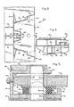
- Fig. 4 is a sectional view taken generally along the line 4-4 in Fig. 3 and additionally illustrating the receiving socket which receives the tongue of a following trailer, an elastomeric load-carrying pad upon which the tongue rests and which allows the tongue to move fore and aft and side to side in relationship to the vertical axis, a portion of the horizontal top plate of the intermodal adapter, which top plate forms the load bearing locating means, also being shown in phantom lines.
- Fig. 5 is an enlarged view similar to Fig. 4, and additionally illustrating how the tongue is secured by a coupler pin to the socket on the rear of a leading trailer.
- Figs. 6 and 7 are sectional views taken generally along the lines 6-6 and 7-7 in Fig. 2.
- Fig. 7A is a sectional view taken generally along the line 7a-7a in Fig. 7.
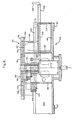
- Fig. 8 is a top plan view of the adapter shown in Fig. 2 showing additional details of its mechanical construction.
- Fig. 9 is a hydraulic and pneumatic schematic.
- Figs. 10-13 are views illustrating how a unit train of highway trailers and railtrucks may be made up.
- FIG. 1 A railway train of highway trailers is shown in Fig. 1 which train corresponds generally to the trains illustrated in applicant's corresponding United States patent application Serial No. 740,650 filed June 3, 1985, the subject matter of which is incorporated herein by reference thereto.
- modified highway trailers 10 are assembled into a unit train as shown in Fig. 1 with the front end of the first leading highway trailer 10a being connected to and supported by a locomotive 11 (or a transition car), with adjacent ends of the highway trailers being supported solely by railtruck assemblies indicated generally at 12, and with the rear end of the last following highway trailer 10n (Fig. 13) also being supported by a railtruck assembly 12.
- An end-of-train lighting device and air pressure monitoring device will be mounted upon the last railtruck of the unit train.
- Each of the railtruck assemblies includes a conventional railtruck and an intermodal adapter.
- the intermodal adapter is, in turn, provided with a load bearing locating surface, a coupler pin, and additional components, all of which will be described in detail below.
- the highway trailers 10 are of a generally conventional design and thus each have a body 14 supported by highway wheel assemblies 16 and which are additionally provided with suitable adjustable support leg assemblies 17.
- Each of the adjustable support leg assemblies include a pair of load supporting, telescoping legs which are mounted at either side of the trailer's longitudinal center line and (in the United States and Canada) are spaced 4 ⁇ 11 1/2" apart which distance is the normal center line distance of the rails of a standard gauge railway track.
- At the lower end of each of the telescope legs there is a plate configured with a longitudinally extending recess which will provide a centering means for the plates when resting upon the head of the track rails and also a flat plane for resting upon a flat surface.
- each of the bodies shown in the drawings are of a monocoque van design, other body styles may be employed.
- each of the bodies may be a van trailer having a load supporting continuous frame, a highway trailer designed to receive detachable containers, a highway trailer for use in carrying automobiles, a highway trailer with a liquid carrying tank mounted thereon, a highway trailer which is surmounted by any type of special purpose body or container, a highway trailer having a telescopic frame for supporting the mountable containers of various lengths or widths or types, etc.
- Each highway trailer will be provided with a forward king pin 18 (Fig. 10) to permit the highway trailer to be connected to a conventional fifth wheel assembly 20 of a tractor 22.
- each of the highway trailers may be used for normal highway transport.
- each highway trailer has all required highway safety features including, but not necessarily limited to bumpers, lights, air brake systems and the like.
- each highway trailer is constructed with appropriate reinforcement that will withstand push and pull (buff and draft) forces in both the highway and railway mode, and will also withstand lateral forces generated by rocking and sway, and upward forces caused by its resting upon the intermodal adapter when in the rail mode.
- each highway trailer is provided with a forwardly extending load supporting tongue 24 (which is apertured at its forward end), and a rail air brake line assembly 26 (Fig. 2).
- the rear end of each trailer is provided with first receiving means 28 (Fig.
- each highway trailer is additionally provided with a highway wheel assembly elevating system 34 which may be of the type shown in U.S. patent 4,568,094 issued February 4, 1986 to Patrick A.
- the forward end of the tongue is provided with a vertically extending hour-glass shaped aperture 38 which is defined by a hardened steel bushing insert 40.
- the first receiving means 28 is located at the rear of the trailer body 14 midway between the side of the body and immediately below the floor 42 of the body. As can best be seen in Fig. 5, the first receiving means includes an upper portion 44 provided with an aperture defined by insert 46, a lower portion 48 provided with a lower coaxially aligned aperture defined by insert 50 and laterally spaced apart sidewalls (not shown). To provide support for the forward end of the apertured tongue, an elastomeric pad assembly is disposed therein, the elastomeric pad assembly including an elastomeric bushing 52 and upper and lower apertured plates 54, 56, respectively, the lower plate 56 being secured to the lower portion 48 by fasteners 58.
- a stop 62 is provided, which stop is mounted on the forward transversely extending wall 64 of the first receiving means by a nut 66.
- the stop is essentially the head of a bolt which is of the proper thickness to insure that the forward end of the tongue will be properly positioned when inserted.
- a guide member 68 is welded or otherwise rigidly secured to the lower portion 48, the guide member 68 having a cam surface 70 which can engage a corresponding cam surface 72 on the lower forward end of the tongue to facilitate the insertion of the tongue into the first receiving means.
- the rear edge of the top plate 54 is also provided with such an angled cam surface 73.
- the second receiving means 30 is best illustrated in Fig. 3. It includes a transversely extending vertical plate 74 which is welded to a horizontal plate 76 (Fig. 4) disposed immediately below the first receiving means and extending forwardly and to the sides of the first receiving means.
- the plate 74 is further reinforced by gussets 78.
- To the sides of the longitudinally extending center line 80 of the trailer are laterally spaced apart angled gathering plates 82 provided at the rear with a transversely extending stop surface 84 reinforced by gussets 86.
- a further angled plate 88 extends from stop surfaces 84 to the rear of the trailer body 14 and is suitably welded in place.
- a nose piece assembly Disposed between the forward ends of the gathering plates 82 is a nose piece assembly consisting of angled plates 90, and spaced apart longitudinal plates 92, these plates also being suitably welded to the horizontal plate 76 and to a lower horizontal plate 94.
- a suitable latching member which can be a U-shaped channel member 96, is rigidly secured to one of the spaced apart longitudinally extending plates 92 and provides a latching surface 97 which can be engaged by a latch carried by the intermodal adapter to secure the intermodal adapter to the second receiving means.
- a suitable cutout 98 is provided in the plate.
- the rail air brake line assembly 26 for the trailer includes a relatively large diameter steel air line pipe 100 (Figs. 2 and 2A) suitably secured to the bottom of the trailer and short front and rear flexible air line sections 102, 104, respectively, ending in "glad hand” air line connectors 106.
- the highway trailer is provided with, near the terminations of the train air line 100, a box or container for inserting the "glad hand” to protect it from the entry of dirt and debris and at the same time supporting it above the lower horizontal surface of the trailer body structure so that the "glad hand" and the associated flexible air line will not catch upon any objects on the highway tractor or elsewhere when the highway trailer is used in the highway mode.
- a tee connection be provided at an appropriate location in the highway brake air line and furthermore that a secondary air line be provided which runs from the tee to a takeoff connection at the rear of the trailer, the air takeoff connection being provided with a suitable shut-off valve.
- Each railtruck assembly consists of an intermodal adapter which is indicated generally at 108 and a conventional two axle, four wheel railtruck indicated generally at 110.
- Each railtruck assembly is provided with a service brake system and a parking brake system.
- the service brake system may be similar to the Buffalo Brake Beam Company "Unipac”, the Westinghouse Air Brake Company “Wabcopac”, etc.
- each of the railtruck assemblies will include suitable control valves, air reservoir, brake crossover piping, flexible air connectors, shut-off cocks, and the like, so as to make the railtruck assembly, in effect, a complete, although, abbreviated rail car.
- the railtruck may be a Dresser model DR-1 radial truck, a Barber stabilized truck model S2-C with appropriate diagonal bracing between side frames, like the Urban Transportation Development Corporation (UTDC) Bracing, or the equivalent.
- UTDC Urban Transportation Development Corporation
- each railtruck includes rail wheels 112 which are supported on the tracks 32, longitudinally extending side frames 114 supported by suitable bearings 116 on axles 118.
- Air operated brake assemblies 119 are carried by the side frames 114.
- a transversely extending bolster 120 supported on the side frames by suitable spring assemblies 122 (Fig. 11).
- the bolster 120 is provided with an apertured centrally located center plate bowl 124 (Fig. 7), and laterally spaced apart portions of the bolster carry constant contact side bearings (not shown).
- a rigid air line 125 is provided which terminates at either end in flexible air lines 126 also provided with "glad hand" air line connectors 106.
- a suitable shut off valve or cock 127 is disposed between the end of the rigid line 125 and the flexible lines 126.
- the intermodal adapter 108 includes a principal welded frame assembly indicated generally at 128 (Fig. 7), the frame assembly being secured at its lower surface to a center plate 130 via ring 132.
- the center plate 130 is in turn provided with a downwardly extending center plate pin 134 which is received within the aperture of the apertured center plate bowl 124 and may be secured with a locking device (not shown).
- additional stabilizing means are provided in the form of forwardly and rearwardly positioned stabilizing pins 136 which are provided with heads 138 at their lower ends, the pins passing between the bolster 120 and front and rear straps 140 which are welded or otherwise rigidly secured to the bolster.
- the purpose of the headed pins (which may be bolts) and straps 140 are to prevent the intermodal adapter 108 overturning during assembly to, or disassembly from, a highway trailer.
- the upper surface of the welded frame assembly is welded or otherwise rigidly secured to load bearing locating means indicated generally at 142.
- the railtruck assembly is bidirectional and thus the load bearing means is also bidirectional.
- the load bearing locating means is provided with substantially identical forwardly and rearwardly extending load bearing and locating portions 144, 146, respectively. These portions are integral with an intermediate load bearing portion 148 (Fig. 8).
- the portions 144, 146 and 148 are all formed from a single metal plate approximately 1.5 inches in thickness which is cut to the appropriate dimensions.
- a central portion of the intermediate portion is cut out and an apertured removable plate 150 is inserted in the cutout, the removable plate being secured in place by fasteners 152 in such a manner that the top surface of the plate 150 is co-extensive with the top surface of the portions 144, 146, 148.
- a coupler pin guide tube 153 is inserted and welded into plate 150 or plate 150 and guide tube 153 may be cast integrally.
- Brackets 154 are welded to laterally spaced apart portions of the intermediate load bearing portion 148 of the load bearing locating means 142 and stops 156 are in turn secured to the top surface of the brackets with the upper surface of the stops lying in the plane of the top surface of the load bearing locating means or preferably slightly below it.
- the portions 144 and 146 have a generally W-shaped configuration which will conform to the second receiving means 30 carried by the body of the trailer.
- each portion 144, 146 has angled beveled sides 158 which can engage the gathering plates 82 and additional angled sides 160 spaced inwardly of the sides 158, the additional angled sides 160 being capable of engaging the angled plates 90 of the nose piece disposed within the second receiving means.
- the welded frame assembly 128 includes two principal transversely extending vertical plate members 162a, 162b. Upper and lower horizontal plate members 164, 166, respectively, are associated with each of the transverse plate members. As shown in Fig. 7, each of the plate members 162a or 162b and its associated upper and lower plate members 164 and 166 are formed from a single I-beam, however, a welded assembly can be utilized. In any event, it will be necessary to provide suitable cutout portions in each of the plates 162, 164, 166 to receive various components of the adapter. In addition, wear plates 167 are provided on the lower surfaces of plates 166, the wear plates 167 being adapted to contact constant contact side bearings on the bolster.
- a pair of laterally spaced apart longitudinally extending plates 168 are disposed between the plate members 162a and 162b and extend from top plate 164 to bottom plate 166.
- Reinforcing plates 170 are also disposed to the forward side of transverse plate 162a and to the rear side of transverse plate 162b, these reinforcing plates in turn being secured at their top edge to the forwardly and rearwardly extending load bearing and locating portions 144 and 146 of the load bearing locating means 142 and at their bottom to bottom plates 166. It can thus be seen that a rigid frame assembly 128 is provided which assembly can easily support the loads imposed upon it.
- a double acting hydraulic cylinder assembly 172 is disposed within a central portion of the welded frame assembly 128, the central portion being defined by plate members 162a, 162b and longitudinally extending plates 168.
- the rod end 174 of the cylinder assembly is coupled to a vertically shiftable coupler pin 176.
- the coupler pin is shown in its lower position in Fig. 7 and in its elevated position in Fig. 5.
- the upper end portion of pin 176 is provided with a tapered surface 177 to facilitate its entry into the bushing 40 and apertured inserts 50 and 46, the apertures in inserts 46 conforming to the upper end of pin 176.
- the pin 176 When the pin 176 is coupled to the apertured tongue, it will be held in double shear and provide a relatively "slackless" coupling of one trailer to another.
- the lower plates 166 are cut out within the central portion and the lower end of the cylinder assembly is fastened to the center plate bowl 130 by fasteners 178.
- Supported on a portion of the frame assembly 128 is a bracket assembly 180 which receives the ABDW brake control valve 182 or any other suitable brake control valve for the railtruck air brakes.
- a bracket 184 is also carried by the frame assembly, the bracket supporting the air reservoir 186.
- An air line 187 extends from line 125 to the ABDW valve, this line also being provided with a suitable shut-off valve 187a.
- latches 188 Forwardly and rearwardly extending substantially identical latches 188 (Figs. 7 and 8) are carried by the adapter, the latches each being pivoted on a vertically extending pin 190. Rigidly secured to each of the latches 188 is an arm 192, the end of the arm 192 remote from the pivot pin 190 being inter-connected to a spring assembly 194 which will normally cause the latch to be biased to its full line position shown in Fig. 8 but which will permit the latch to be swung to its dotted line position when the outer cam surface 196 of the latch is engaging the latch member 96 during assembly of the railtruck assembly to the rear receiving means 30 of a highway trailer.
- a spring assembly 194 which will normally cause the latch to be biased to its full line position shown in Fig. 8 but which will permit the latch to be swung to its dotted line position when the outer cam surface 196 of the latch is engaging the latch member 96 during assembly of the railtruck assembly to the rear receiving means 30 of a highway trailer
- the planar surface 198 of the latch will engage the latching surface 97 of the latch member 196 to hold the parts together and the stops 156 will engage the surfaces 84.
- the engagement between the latching surfaces 198 and 97, as well as other engagements, will provide brake torque reacting means whereby the intermodal adapter will resist tipping forward when the brakes of the rail truck are applied.
- latch release lever is provided for each latch.
- the mechanism for releasing the forward latch 188 as shown in Fig. 8 will be to the left hand side of the railtruck and disposed as far as possible to the rear. This location is desirable since the latch release mechanism should be disposed to the rear of the trailer when coupled to the railtruck assembly, and should also be preferably on the driver side of the vehicle which will be used to transport the trailer away from the adapter. Since the railtruck assembly is designed for coupling to a trailer in either direction, another latch release mechanism is provided for releasing the rear latch as shown in Fig. 8, this mechanism being disposed in a forward right hand position.
- the latch release mechanism includes a rock shaft 200 journalled on the intermodal adapter frame, the inner end of the rock shaft being connected to a link 202 by a rock arm 204.
- the other end of the rock shaft 200 is provided with a suitable manually engageable handle 206.
- the rock shaft 200 is supported by a suitable bearing which, for example, may simply be a tube 208.
- a coupler pin indicating mechanism is provided.
- the coupler indicator rods 210 extend to either side of the welded frame assembly 128.
- the coupler pins will extend outwardly as shown in phantom lines in Fig. 8, but will otherwise be in their full line position.
- the coupler indicator rods are caused to be operated by a yoke or fork member 212. The spaced apart arms of the member 212 are received within cutouts 214 in the coupler guide tube 153.
- the member 212 is carried by the rod end of a single acting air cylinder assembly 216, the rod normally being spring biased to the right hand position as shown in Fig. 8 but which may be retracted by the operation of the cylinder assembly when air is introduced into the cylinder . It alternatively may be desirable to operate the lock fork 212 by suitable manual means, thus eliminating the cylinder 216 in its entirety and substituting therefor an appropriate mechanical lever means with a similar spring bias means.
- the coupler pin 176 When the coupler pin 176 is in its fully raised position, the bottom of the coupler pin will be above the upper surface of the cutouts 214 and the yoke 212 can then extend beneath the coupler pin and straddle the rod 174.
- the yoke When in this position, the yoke will not only serve to indicate the position of the coupler pin, but will also prevent the coupler pin from dropping in the event that there is a loss of hydraulic fluid from the cylinder assembly 172.
- the yoke carries a bracket 218 through which one of the indicator rods 210 passes, the rod 210 being secured to the bracket in any conventional manner.
- One end of the rod 210 is pivotally secured to a pivoting link 220 and the inner end of the other rod is secured to the other end of the pivoting link, the link pivoting about a centrally located pivot pin 222. It can be seen from an inspection of Fig.
- the housing 223 for reservoir 224 for the hydraulic cylinder assembly 172 is mounted upon the lower plate 166 to the right of the right hand longitudinally extending plate member 168 as best shown in Fig. 6.
- Mounted above the housing 223 is an air motor 226 which is coupled by a power take-off shaft 227 (Fig. 9) to a pump 228 disposed within the housing.
- the pump 228 as well as other various hydraulic components disposed within the housing 223 are not shown in detail but they are illustrated in the schematic diagram Fig. 9).
- the hydraulic pump 228 is powered by the air motor 226 as pressurized air is usually readily available in both trains and from highway tractors.
- the various air lines associated with the hydraulic system are only shown in Fig. 9 but it should be noted that as the railtruck assembly of this invention is to be bi-directional, inlet air couplings 230 are disposed to either side of the railtruck assembly.
- Air will additionally flow from junction J1 through a branch line 250 (provided with junction J2) to the single acting spring biased air cylinder 216 which will cause the fork 212 to be shifted away from the axis of the coupler pin 176.
- a check valve and variable restricter assembly 251 is provided in line 250 between junction J2 and the cylinder assembly 216.
- a blocking valve 252 is disposed in another branch line 254 which extends away from junction J2, the blocking valve normally being disposed in its blocking position.
- this valve can be shifted to an open position by means of a roller 256 which is engaged by structure 257 interconnected to the yoke 214 and which will shift the blocking valve 252 to its open position when the yoke is in its fully retracted position.
- Air will now be supplied to both of the control valves 234L and 234R.
- the operator will shift the lever 258L, which operates valve 234L, in the desired direction to shift the valve to its desired position wherein air will now be permitted to flow through the valve 234L, through the raise selector valve 260 and then through pilot line 262 which will shift the hydraulic control valve 232 to its desired position wherein the coupler pin may be raised.
- the air motor 226 is driving the hydraulic pump 228 which draws fluid from the reservoir 224 through filter 264, the pump discharging its output through line 266 which is connected to the anchor end of the cylinder assembly 172 causing the rod 174 to be extended outwardly of the cylinder.
- valve 232 When valve 232 is in the neutral position, the air motor will stall and no oil will be pumped. This is to prevent frothing of oil when the pump is "short circuited".
- a pressure relief valve 268 is disposed within the housing 223 in connection with the line 266, the valve diverting excess fluid back to the reservoir when either the pin has attained its fully raised position, or when the lift pressure exerted by the pin is excessive, as may be possible when the tongue and/or load bearing adapter plate are not properly positioned with respect to the rear end of the leading trailer.
- the load bearing locating plate should be latched within the second receiving means of the trailer so that the coupler pin 176 is in alignment with the spaced apart apertures in the first receiving means, and additionally, the tongue should be fully inserted within the first receiving means so that its forward aperture is also in alignment with the spaced apart apertures, the coupler pin and all of which various apertures being concentric with the axis A of the center plate bowl.
- a backup manual hydraulic pump 276 is provided.
- This pump can also be disposed within the housing 223 and is provided with lines which extend to either side of the pump 228.
- check valves 278 are provided.
- a tap is provided off the brake air reservoir 186 which can be used for the purpose of actuating the cylinder 216.
- a spring biased pilot operated selector valve 282 is provided in the branch line 250 which extends to the cylinder 216, the selector valve normally being spring biased to a position where external air will pass through the selector valve but which may be pilot operated to permit air to flow from the reservoir 186 when desired.
- the control 286 for valve 284 will be engaged by the operating handle provided for operating the pump 276 when the handle is inserted within its receiving socket. It will also be necessary for the operator to engage one of the control levers 258.
- Figs. 10-13 The manner in which a unit railway train of highway vehicles is assembled is illustrated in Figs. 10-13 and a manner in which they are broken up would follow the reverse procedure of Figs. 13-10.
- the kingpin 18 of a trailer will be engaged by the fifth wheel assembly 20 on tractor 22 and the highway wheel elevating system is operated to cause the body 14 of the trailer to be raised.
- the highway trailer 10 is now backed towards the railtruck assembly 12 until the second receiving means 30 of the trailer. (Alternatively the railtruck assembly 12 can be moved forwardly towards the trailer 10.) If the trailer is not in proper longitudinal alignment, engagement of the side surfaces 158 (Fig. 8) with the plates 82 (Fig.
- the rear flexible air line section 104 (Fig. 2) on highway trailer 10n is connected to the forwardly located flexible air line section 126 (Fig. 2) on the railtruck assembly 12.
- Another highway trailer is now connected to another railtruck assembly, this railtruck assembly being disposed forwardly of the first trailer assembled onto a railtruck (10n in Figs. 10-13).
- the leading trailer (10n-1) and associated railtruck assembly are now backed towards the first highway trailer (10n) assembled onto a railtruck until the tongue 24 of the following highway trailer (10n) is fully received within the first receiving means 28 of trailer 10n-1.
- the coupler pin 176 is caused to be raised by the hydraulic cylinder assembly 172 either through the operation of an external air source or by operation of a manual pump.
- the indicator rods 210 (Fig. 8) will extend outwardly to indicate that the pin is fully raised.
- the fork 212 (Fig. 8) will be disposed beneath a portion of the coupler pin and prevent it from dropping in the event that there is a leak in the hydraulic system. It is now only necessary to connect the brake air line sections 102 and 104 on trailers 10n and 10n-1, respectively, to the associated brake lines 126 (Fig. 2) on the railtruck and to raise the support legs 17 of the trailer 10n and to lower the legs 17 of trailer 10n-1. The steps set forth above are continued until the unit train is fully made up.
- an air operated jack such as a worm gear driven screw jack
- the yoke which supports the coupler pin when in its fully raised position, may alternatively be operated manually.
- the air cylinder 216 which operates the safety latch 212, can be eliminated in which case the safety latch 212 can be operated by the indicator rods 210. If this is done, it will be necessary to eliminate the enabling valves 240. In addition, it will also be possible to eliminate the check valve and restrictor 251 and valve 252.
Priority Applications (1)
| Application Number | Priority Date | Filing Date | Title |
|---|---|---|---|
| AT87108093T ATE63506T1 (de) | 1986-06-19 | 1987-06-04 | Eisenbahnzug fuer strassenfahrzeuge und elemente dafuer. |
Applications Claiming Priority (2)
| Application Number | Priority Date | Filing Date | Title |
|---|---|---|---|
| US06/876,248 US4841872A (en) | 1985-06-03 | 1986-06-19 | Railway train of highway vehicles, and components therefor |
| US876248 | 1992-04-30 |
Publications (3)
| Publication Number | Publication Date |
|---|---|
| EP0249816A2 EP0249816A2 (en) | 1987-12-23 |
| EP0249816A3 EP0249816A3 (en) | 1988-02-24 |
| EP0249816B1 true EP0249816B1 (en) | 1991-05-15 |
Family
ID=25367272
Family Applications (1)
| Application Number | Title | Priority Date | Filing Date |
|---|---|---|---|
| EP87108093A Expired - Lifetime EP0249816B1 (en) | 1986-06-19 | 1987-06-04 | Improved railway train of highway vehicles and components therefor |
Country Status (15)
| Country | Link |
|---|---|
| US (1) | US4841872A (ja) |
| EP (1) | EP0249816B1 (ja) |
| CN (1) | CN1007140B (ja) |
| AT (1) | ATE63506T1 (ja) |
| AU (1) | AU595617B2 (ja) |
| BR (1) | BR8703070A (ja) |
| CA (1) | CA1286153C (ja) |
| DE (1) | DE3770053D1 (ja) |
| ES (1) | ES2022205B3 (ja) |
| GR (1) | GR3002240T3 (ja) |
| IN (1) | IN170266B (ja) |
| MX (1) | MX168936B (ja) |
| NZ (1) | NZ220545A (ja) |
| SU (1) | SU1612993A3 (ja) |
| ZA (1) | ZA874152B (ja) |
Families Citing this family (34)
| Publication number | Priority date | Publication date | Assignee | Title |
|---|---|---|---|---|
| IT211419Z2 (it) * | 1987-03-10 | 1989-03-06 | Cima | Dispositivo di aggancio applicabile su carrelli ferroviari, perl'accoppiamento tra vetture a trasporto bimodale appositamente predisposte. |
| US5280939A (en) * | 1989-09-28 | 1994-01-25 | Advance Engineered Products Ltd. | Steering control systems for "C" dollies and the like |
| DE4442503A1 (de) * | 1994-11-30 | 1996-06-05 | Linke Hofmann Busch | Bremssystem für Ganzzüge |
| US5537931A (en) * | 1995-04-21 | 1996-07-23 | Wabash National Corporation | Bogie adapter for intermodal trailer |
| CA2228707A1 (en) * | 1997-02-04 | 1998-08-04 | Railrunner Systems, Inc. | Improved intermodal vehicle for forming a train of highway trailers |
| US20010028160A1 (en) | 1999-02-26 | 2001-10-11 | Athans George C. | Self-lubricating trailer bearing plate for fifth wheel |
| US6322093B1 (en) * | 1999-07-26 | 2001-11-27 | Direct Dimensions Inc. | Double shear trailer bearing plate for fifth wheel |
| AUPP923299A0 (en) | 1999-03-16 | 1999-04-15 | Air-Ride (S.A.) Pty Ltd | Improved coupling arrangement for train of highway trailers |
| FR2818930B1 (fr) | 2001-01-03 | 2003-04-04 | Christian Louveau | Dispositif de tracteur traditionnel sur rails transformable en tracteur railroute et tractable a grande vitesse dans un convoi ferroviaire |
| FR2820366B1 (fr) | 2001-02-08 | 2003-05-30 | Christian Louveau | Dispositif de guidage ferroviaire moteur et auto-directeur avec suspension hydraulique independante adaptable aux vehicules routiers |
| EP1378380A1 (fr) | 2002-07-01 | 2004-01-07 | Christian Louveau | Tracteur rail-route tractable à grande vitesse |
| EP1378381A1 (fr) | 2002-07-01 | 2004-01-07 | Christian Louveau | Dispositif de guidage moteur et auto-directeur |
| SE0202776L (sv) * | 2002-09-19 | 2003-08-19 | Sjoelanders Smides Och Mek Ver | Fordon för olika typer av körning samt sätt att köra sådant fordon |
| US7306295B2 (en) * | 2003-03-05 | 2007-12-11 | New York Air Brake Corporation | Pump system for parking brakes for a rail vehicle |
| FR2874566B1 (fr) * | 2004-08-27 | 2006-12-29 | Alstom Transport Sa | Rame articulee de chemin de fer |
| CL2007003736A1 (es) * | 2006-12-20 | 2008-05-16 | Railrunner Na Inc | Bastidor bimodal para contenedor de transporte, que comprende un marco principal con un primer y segundo extremo y bordes superior e inferior; conjunto de elementos rodantes conectados al marco y movil a lo largo del borde inferior en una primera y s |
| FR2913938B1 (fr) * | 2007-03-19 | 2009-05-08 | Lohr Ind | Ensemble d'arrimage a immobilisation totale et autocentrage d'un pivot d'attelage d'une semi-remorque sur une unite ferroviaire. |
| US20090151596A1 (en) * | 2007-12-12 | 2009-06-18 | William Harvey Sproat | Fastload rail carrier for motor vehicles, freight and passengers |
| EP2483188B1 (en) * | 2009-09-30 | 2017-12-20 | Donald D. Banwart | Intermodal transportation system with movable loading ramps and local hybrid delivery |
| CN102712322B (zh) * | 2009-12-07 | 2015-11-25 | 铁路赛跑者N.A.公司 | 改进的用于形成列车的联运铁路车辆 |
| CN102295005A (zh) * | 2010-06-17 | 2011-12-28 | 王文林 | 全自动不停车、车候人轨道交通系统 |
| CN102161300B (zh) * | 2010-12-24 | 2013-01-16 | 重庆大学 | 队列式电动汽车的连接器 |
| CN102491102B (zh) * | 2011-12-21 | 2013-06-12 | 吉林省明普光学科技有限公司 | 一种铁路港口转运散货装卸作业方法和系统 |
| DE102012205282A1 (de) * | 2012-03-30 | 2013-10-02 | Siemens Aktiengesellschaft | Übergangskupplung, Fahrzeugverbund mit zumindest zwei Fahrzeugen, deren Kupplungsvorrichtungen mittels einer derartigen Übergangskupplung gekuppelt sind, und Verfahren zum Kuppeln von Kupplungsvorrichtungen zweier Fahrzeuge. |
| WO2013167595A1 (en) * | 2012-05-08 | 2013-11-14 | Cede Group Ab | Drive unit for a road-rail vehicle |
| CN102700370A (zh) * | 2012-06-07 | 2012-10-03 | 朱瑞彪 | 一种公路铁路两用挂车 |
| CN103818395B (zh) * | 2012-11-16 | 2017-11-17 | 海运快速有限责任公司 | 用于支承具有宽底路轨车轮的联运货物轨道车辆的装置 |
| CN103979028A (zh) * | 2013-03-27 | 2014-08-13 | 黄远杰 | 小汽车公交化运输系统 |
| US10745037B2 (en) * | 2015-04-28 | 2020-08-18 | China Academy Of Railway Sciences | Fully continuous ground measurement method and system for wheel rail vertical force |
| CN105197057B (zh) * | 2015-10-12 | 2017-07-14 | 长春轨道客车装备有限责任公司 | 列车可变位牵引工装 |
| CN106740916A (zh) * | 2017-01-05 | 2017-05-31 | 北京首钢国际工程技术有限公司 | 一种可主动转向的自行驶钢卷运输车 |
| US10787184B2 (en) | 2017-04-06 | 2020-09-29 | Twenty-First Century Transportation Systems, Inc,. | Intermodal transportation system including guide rails and autonomous transport dollies |
| AU2019311716B2 (en) * | 2018-07-27 | 2021-08-05 | Crrc Yangtze Co., Ltd. | Road-rail dual-purpose vehicle |
| US11845313B1 (en) * | 2020-03-09 | 2023-12-19 | Randall Karl Ashbaugh | Truck trailer with retractable wheels for use with a railroad track |
Family Cites Families (50)
| Publication number | Priority date | Publication date | Assignee | Title |
|---|---|---|---|---|
| GB287955A (en) * | 1926-12-23 | 1928-03-23 | Philip Armroid Hyde | Improved means for carrying locomotives, carriages, machinery and the like on railways |
| US1786463A (en) * | 1929-09-07 | 1930-12-30 | David R Thomas | Trailer construction |
| US2036535A (en) * | 1933-02-21 | 1936-04-07 | Charles A Nelson | Method of and apparatus for transporting goods |
| US2170095A (en) * | 1935-03-04 | 1939-08-22 | George T Ronk | Truck |
| US2035535A (en) * | 1935-07-18 | 1936-03-31 | Colmorgen George | Wheelbarrow |
| US2230090A (en) * | 1939-06-08 | 1941-01-28 | Ruth Rosholt | Vehicle-combination road and rail |
| US2513552A (en) * | 1947-10-16 | 1950-07-04 | Carl D Dove | Combined highway and rail freight unit |
| US2638852A (en) * | 1950-01-24 | 1953-05-19 | John A Bannen | Rail trailer carrier |
| US2709969A (en) * | 1950-01-30 | 1955-06-07 | Carl H Nyssen | Combination railway and highway vehicle |
| US2800086A (en) * | 1954-04-05 | 1957-07-23 | Ralph A Wike | Convertible vehicle |
| US2787971A (en) * | 1954-06-04 | 1957-04-09 | Andrew N Obes | Method for the transportation of freight |
| US2841094A (en) * | 1955-04-12 | 1958-07-01 | Leon B Schumacher | System of transporting highway vehicles by rail |
| US2826155A (en) * | 1955-06-14 | 1958-03-11 | Ohio Brass Co | Coupler for articulated vehicles |
| US2889785A (en) * | 1955-11-23 | 1959-06-09 | Chesapeake & Ohio Railway | Road-rail vehicle |
| US2816517A (en) * | 1956-06-01 | 1957-12-17 | Pullman Standard Car Mfg Co | Axle steering lock |
| US2963986A (en) * | 1956-10-25 | 1960-12-13 | Dominion Foundries & Steel | Combined highway and rail freight units |
| US2920580A (en) * | 1958-01-07 | 1960-01-12 | Williams Byron | Loading semi-trailers on railway cars |
| US2925791A (en) * | 1958-03-27 | 1960-02-23 | Chesapeake & Ohio Railway | Road-rail vehicle coupling and transfer mechanism |
| US3002469A (en) * | 1959-07-06 | 1961-10-03 | Gen Motors Corp | Suspension system for vehicle having alternate ground engaging wheel sets |
| US3081115A (en) * | 1961-01-11 | 1963-03-12 | Gen Motors Corp | Semi-trailer kingpin receiving means |
| US3286654A (en) * | 1963-06-22 | 1966-11-22 | Earl H Fisher | Convertible rail-highway vehicle |
| US3286657A (en) * | 1963-08-13 | 1966-11-22 | Chesapeake & Ohio Railway | Railway-highway vehicle truck |
| DE1455169A1 (de) * | 1964-12-28 | 1969-03-27 | Perrot Pierre Georges Joseph | Sattelschlepperanhaenger fuer Verwendung auf Schiene und Strasse |
| US3342141A (en) * | 1965-05-03 | 1967-09-19 | Chesapeake & Ohio Railway | Convertible rail-highway vehicle truck |
| US3371622A (en) * | 1965-10-18 | 1968-03-05 | Gen Steel Ind Inc | Articulated car |
| FR1512601A (fr) * | 1966-12-30 | 1968-02-09 | Venissieux Atel | Dispositif de liaison entre deux parties d'un véhicule ferroviaire et un bogie intermédiaire sur lequel elles prennent appui |
| US3687084A (en) * | 1969-07-17 | 1972-08-29 | Acf Ind Inc | Articulated car train |
| US3721199A (en) * | 1970-11-16 | 1973-03-20 | Amsted Ind Inc | Articulated container car |
| US3812791A (en) * | 1972-07-27 | 1974-05-28 | Maxson Corp | Adjustable flat car |
| US4202277A (en) * | 1977-06-27 | 1980-05-13 | Bi-Modal Corporation | Convertible rail-highway semi-trailer |
| US4202454A (en) * | 1977-06-27 | 1980-05-13 | Bi-Modal Corporation | Coupler to connect convertible rail-highway vehicles end to end |
| US4202276A (en) * | 1977-06-27 | 1980-05-13 | Bi-Modal Corporation | Self-steering wheel-set for convertible railway vehicle |
| US4179997A (en) * | 1977-12-23 | 1979-12-25 | Intermodal Concepts, Inc. | Rail-highway intermodal freight carrier transport system |
| CH632707A5 (fr) * | 1979-11-26 | 1982-10-29 | Albert Adams | Vehicule pour le transport ferroviaire et routier de marchandises. |
| US4342265A (en) * | 1980-02-28 | 1982-08-03 | Bi-Modal Corp. | Convertible rail-highway semi-trailer axle lifting and retaining mechanism |
| US4381713A (en) * | 1980-05-01 | 1983-05-03 | Bi-Modal Corporation | Convertible rail-highway semi-trailer air controlled braking and suspension shifting system |
| US4316418A (en) * | 1980-05-01 | 1982-02-23 | Bi-Modal Corporation | Convertible rail highway semi-trailer air controlled suspension shifting system |
| US4456413A (en) * | 1980-05-08 | 1984-06-26 | The Budd Company | Low level freight car for carrying trailers |
| US4364315A (en) * | 1980-08-29 | 1982-12-21 | Rail-Or-Trail Corp. | Convertible rail-highway vehicle support system |
| US4474707A (en) * | 1980-10-09 | 1984-10-02 | American Home Products Corporation | N-3-Propenylaminopropyl-N'-phenylureas |
| US4400121A (en) * | 1981-01-26 | 1983-08-23 | The Budd Company | Railway car hitch for a trailer |
| US4416571A (en) * | 1981-02-17 | 1983-11-22 | Krause Robert A | Truck and rail transportation system |
| US4397243A (en) * | 1981-03-02 | 1983-08-09 | A. F. Hickman Associates, Inc. | Convertible highway railroad vehicle |
| US4452147A (en) * | 1981-03-10 | 1984-06-05 | The Youngstown Steel Door Company | Intermodal railway car |
| US4448132A (en) * | 1981-09-17 | 1984-05-15 | Beatty William T | Convertible railway-highway vehicle |
| NO159523C (no) * | 1983-11-23 | 1989-01-11 | Trailer Train Ltd | Transportsystem omfattende semitrailere og skinneboggier,samt skinnetog omfattende flere slike semitrailere. |
| DE3344513A1 (de) * | 1983-12-09 | 1985-06-20 | Ackermann-Fruehauf Corporation & Co Ohg, 5600 Wuppertal | Kombiniertes strassen- und bahn-transportsystem |
| US4585133A (en) * | 1984-04-12 | 1986-04-29 | Amsted Industries Incorporated | Coupler for convertible rail-highway semi-trailer |
| GB2168020B (en) * | 1984-12-04 | 1989-01-25 | Railmaster System Inc | Railway highway vehicle |
| US4665834A (en) * | 1985-08-16 | 1987-05-19 | Sea-Land Service Inc. | Apparatus for intermodal transport of highway containers |
-
1986
- 1986-06-19 US US06/876,248 patent/US4841872A/en not_active Expired - Lifetime
-
1987
- 1987-06-03 NZ NZ220545A patent/NZ220545A/xx unknown
- 1987-06-04 DE DE8787108093T patent/DE3770053D1/de not_active Expired - Lifetime
- 1987-06-04 IN IN415/MAS/87A patent/IN170266B/en unknown
- 1987-06-04 ES ES87108093T patent/ES2022205B3/es not_active Expired - Lifetime
- 1987-06-04 EP EP87108093A patent/EP0249816B1/en not_active Expired - Lifetime
- 1987-06-04 AT AT87108093T patent/ATE63506T1/de not_active IP Right Cessation
- 1987-06-08 CA CA000539101A patent/CA1286153C/en not_active Expired - Lifetime
- 1987-06-10 ZA ZA874152A patent/ZA874152B/xx unknown
- 1987-06-16 AU AU74405/87A patent/AU595617B2/en not_active Ceased
- 1987-06-18 BR BR8703070A patent/BR8703070A/pt unknown
- 1987-06-18 MX MX006984A patent/MX168936B/es unknown
- 1987-06-18 SU SU874203044A patent/SU1612993A3/ru active
- 1987-06-19 CN CN87104292A patent/CN1007140B/zh not_active Expired
-
1991
- 1991-07-03 GR GR91400950T patent/GR3002240T3/el unknown
Also Published As
| Publication number | Publication date |
|---|---|
| AU7440587A (en) | 1988-01-07 |
| AU595617B2 (en) | 1990-04-05 |
| EP0249816A3 (en) | 1988-02-24 |
| ES2022205B3 (es) | 1991-12-01 |
| EP0249816A2 (en) | 1987-12-23 |
| BR8703070A (pt) | 1988-03-08 |
| SU1612993A3 (ru) | 1990-12-07 |
| CA1286153C (en) | 1991-07-16 |
| CN87104292A (zh) | 1988-07-20 |
| CN1007140B (zh) | 1990-03-14 |
| MX168936B (es) | 1993-06-15 |
| NZ220545A (en) | 1988-10-28 |
| ATE63506T1 (de) | 1991-06-15 |
| ZA874152B (en) | 1987-12-11 |
| GR3002240T3 (en) | 1992-12-30 |
| IN170266B (ja) | 1992-03-07 |
| US4841872A (en) | 1989-06-27 |
| DE3770053D1 (de) | 1991-06-20 |
Similar Documents
| Publication | Publication Date | Title |
|---|---|---|
| EP0249816B1 (en) | Improved railway train of highway vehicles and components therefor | |
| US4669391A (en) | Train of highway trailers | |
| EP0688280B1 (en) | Intermodal vehicle for forming train of trailers | |
| US4917020A (en) | Transition vehicle for use with convertible rail-highway trailers | |
| US6460468B1 (en) | Intermodal transport system | |
| US6491352B2 (en) | Spring applied parking brake for rail cars | |
| US6718886B2 (en) | Ramp car | |
| DE2827738A1 (de) | Sattelanhaenger fuer den schienenund strassenbetrieb | |
| US4955292A (en) | Dual-mode rail-highway semi-trailer with separable bogie | |
| EP2231458B1 (en) | Improved intermodal rail vehicle to form a train | |
| CA1188154A (en) | Convertible rail-highway semi-trailer air controlled braking and suspension shifting system | |
| US4766818A (en) | Train of highway trailers and method of making | |
| WO1990014978A1 (en) | Ramp systems for assembling and disassembling highway trailers and railtrucks for intermodal transportation | |
| US4386880A (en) | Trailer transporting rail-way car | |
| US5040466A (en) | Train of highway trailers and method of making | |
| US5620195A (en) | Locking system for a semitrailer sliding undercarriage with air pressure protection valve | |
| US5537931A (en) | Bogie adapter for intermodal trailer | |
| EP1241069A1 (en) | Spring applied parking brake for railcars | |
| US4981083A (en) | Dual-mode rail-highway semi-trailer | |
| US5890433A (en) | Intermodal vehicle for forming train of trailers | |
| US4907514A (en) | Train of highway trailers and method of making | |
| AU2008201316B2 (en) | Ramp car | |
| AU782675B2 (en) | Spring applied parking brake for rail cars | |
| AU2002318889B2 (en) | Ramp Car | |
| CA2370807A1 (en) | Spring applied parking brake for railcars |
Legal Events
| Date | Code | Title | Description |
|---|---|---|---|
| PUAI | Public reference made under article 153(3) epc to a published international application that has entered the european phase |
Free format text: ORIGINAL CODE: 0009012 |
|
| AK | Designated contracting states |
Kind code of ref document: A2 Designated state(s): AT BE CH DE ES FR GB GR IT LI LU NL SE |
|
| PUAL | Search report despatched |
Free format text: ORIGINAL CODE: 0009013 |
|
| RHK1 | Main classification (correction) |
Ipc: B61D 3/18 |
|
| AK | Designated contracting states |
Kind code of ref document: A3 Designated state(s): AT BE CH DE ES FR GB GR IT LI LU NL SE |
|
| 17P | Request for examination filed |
Effective date: 19880630 |
|
| 17Q | First examination report despatched |
Effective date: 19890713 |
|
| GRAA | (expected) grant |
Free format text: ORIGINAL CODE: 0009210 |
|
| AK | Designated contracting states |
Kind code of ref document: B1 Designated state(s): AT BE CH DE ES FR GB GR IT LI LU NL SE |
|
| PG25 | Lapsed in a contracting state [announced via postgrant information from national office to epo] |
Ref country code: GR Free format text: LAPSE BECAUSE OF FAILURE TO SUBMIT A TRANSLATION OF THE DESCRIPTION OR TO PAY THE FEE WITHIN THE PRESCRIBED TIME-LIMIT Effective date: 19910515 |
|
| REF | Corresponds to: |
Ref document number: 63506 Country of ref document: AT Date of ref document: 19910615 Kind code of ref document: T |
|
| ITF | It: translation for a ep patent filed |
Owner name: JACOBACCI & PERANI S.P.A. |
|
| REF | Corresponds to: |
Ref document number: 3770053 Country of ref document: DE Date of ref document: 19910620 |
|
| PG25 | Lapsed in a contracting state [announced via postgrant information from national office to epo] |
Ref country code: LU Free format text: LAPSE BECAUSE OF NON-PAYMENT OF DUE FEES Effective date: 19910630 |
|
| ET | Fr: translation filed | ||
| PLBE | No opposition filed within time limit |
Free format text: ORIGINAL CODE: 0009261 |
|
| STAA | Information on the status of an ep patent application or granted ep patent |
Free format text: STATUS: NO OPPOSITION FILED WITHIN TIME LIMIT |
|
| 26N | No opposition filed | ||
| PGFP | Annual fee paid to national office [announced via postgrant information from national office to epo] |
Ref country code: AT Payment date: 19920611 Year of fee payment: 6 |
|
| PGFP | Annual fee paid to national office [announced via postgrant information from national office to epo] |
Ref country code: SE Payment date: 19920615 Year of fee payment: 6 Ref country code: CH Payment date: 19920615 Year of fee payment: 6 |
|
| PGFP | Annual fee paid to national office [announced via postgrant information from national office to epo] |
Ref country code: NL Payment date: 19920630 Year of fee payment: 6 |
|
| REG | Reference to a national code |
Ref country code: GR Ref legal event code: FG4A Free format text: 3002240 |
|
| PGFP | Annual fee paid to national office [announced via postgrant information from national office to epo] |
Ref country code: BE Payment date: 19920903 Year of fee payment: 6 |
|
| PG25 | Lapsed in a contracting state [announced via postgrant information from national office to epo] |
Ref country code: AT Effective date: 19930604 |
|
| PG25 | Lapsed in a contracting state [announced via postgrant information from national office to epo] |
Ref country code: SE Effective date: 19930605 |
|
| PG25 | Lapsed in a contracting state [announced via postgrant information from national office to epo] |
Ref country code: LI Effective date: 19930630 Ref country code: CH Effective date: 19930630 Ref country code: BE Effective date: 19930630 |
|
| ITPR | It: changes in ownership of a european patent |
Owner name: CESSIONE;WABASH NATIONAL CORPORATION |
|
| BERE | Be: lapsed |
Owner name: RAILMASTER SYSTEM INC. Effective date: 19930630 |
|
| PG25 | Lapsed in a contracting state [announced via postgrant information from national office to epo] |
Ref country code: NL Effective date: 19940101 |
|
| NLV4 | Nl: lapsed or anulled due to non-payment of the annual fee | ||
| REG | Reference to a national code |
Ref country code: CH Ref legal event code: PL |
|
| REG | Reference to a national code |
Ref country code: ES Ref legal event code: PC2A Owner name: WABASH NATIONAL CORPORATION |
|
| REG | Reference to a national code |
Ref country code: GR Ref legal event code: MM2A Free format text: 3002240 |
|
| EUG | Se: european patent has lapsed |
Ref document number: 87108093.3 Effective date: 19940110 |
|
| REG | Reference to a national code |
Ref country code: GB Ref legal event code: 732E |
|
| REG | Reference to a national code |
Ref country code: FR Ref legal event code: TP |
|
| REG | Reference to a national code |
Ref country code: GB Ref legal event code: IF02 |
|
| PGFP | Annual fee paid to national office [announced via postgrant information from national office to epo] |
Ref country code: GB Payment date: 20040609 Year of fee payment: 18 |
|
| PGFP | Annual fee paid to national office [announced via postgrant information from national office to epo] |
Ref country code: DE Payment date: 20040617 Year of fee payment: 18 |
|
| PGFP | Annual fee paid to national office [announced via postgrant information from national office to epo] |
Ref country code: FR Payment date: 20040625 Year of fee payment: 18 |
|
| PGFP | Annual fee paid to national office [announced via postgrant information from national office to epo] |
Ref country code: ES Payment date: 20040719 Year of fee payment: 18 |
|
| PG25 | Lapsed in a contracting state [announced via postgrant information from national office to epo] |
Ref country code: IT Free format text: LAPSE BECAUSE OF NON-PAYMENT OF DUE FEES;WARNING: LAPSES OF ITALIAN PATENTS WITH EFFECTIVE DATE BEFORE 2007 MAY HAVE OCCURRED AT ANY TIME BEFORE 2007. THE CORRECT EFFECTIVE DATE MAY BE DIFFERENT FROM THE ONE RECORDED. Effective date: 20050604 Ref country code: GB Free format text: LAPSE BECAUSE OF NON-PAYMENT OF DUE FEES Effective date: 20050604 |
|
| PG25 | Lapsed in a contracting state [announced via postgrant information from national office to epo] |
Ref country code: ES Free format text: LAPSE BECAUSE OF NON-PAYMENT OF DUE FEES Effective date: 20050606 |
|
| PG25 | Lapsed in a contracting state [announced via postgrant information from national office to epo] |
Ref country code: DE Free format text: LAPSE BECAUSE OF NON-PAYMENT OF DUE FEES Effective date: 20060103 |
|
| PG25 | Lapsed in a contracting state [announced via postgrant information from national office to epo] |
Ref country code: FR Free format text: LAPSE BECAUSE OF NON-PAYMENT OF DUE FEES Effective date: 20060228 |
|
| GBPC | Gb: european patent ceased through non-payment of renewal fee |
Effective date: 20050604 |
|
| REG | Reference to a national code |
Ref country code: FR Ref legal event code: ST Effective date: 20060228 |
|
| REG | Reference to a national code |
Ref country code: ES Ref legal event code: FD2A Effective date: 20050606 |