US4342265A - Convertible rail-highway semi-trailer axle lifting and retaining mechanism - Google Patents
Convertible rail-highway semi-trailer axle lifting and retaining mechanism Download PDFInfo
- Publication number
- US4342265A US4342265A US06/125,507 US12550780A US4342265A US 4342265 A US4342265 A US 4342265A US 12550780 A US12550780 A US 12550780A US 4342265 A US4342265 A US 4342265A
- Authority
- US
- United States
- Prior art keywords
- axle unit
- hook member
- rail
- air
- set axle
- Prior art date
- Legal status (The legal status is an assumption and is not a legal conclusion. Google has not performed a legal analysis and makes no representation as to the accuracy of the status listed.)
- Expired - Lifetime
Links
Images


Classifications
-
- B—PERFORMING OPERATIONS; TRANSPORTING
- B61—RAILWAYS
- B61D—BODY DETAILS OR KINDS OF RAILWAY VEHICLES
- B61D3/00—Wagons or vans
- B61D3/16—Wagons or vans adapted for carrying special loads
- B61D3/18—Wagons or vans adapted for carrying special loads for vehicles
- B61D3/182—Wagons or vans adapted for carrying special loads for vehicles specially adapted for heavy vehicles, e.g. public work vehicles, trucks, trailers
- B61D3/184—Wagons or vans adapted for carrying special loads for vehicles specially adapted for heavy vehicles, e.g. public work vehicles, trucks, trailers the heavy vehicles being of the trailer or semi-trailer type
-
- B—PERFORMING OPERATIONS; TRANSPORTING
- B60—VEHICLES IN GENERAL
- B60F—VEHICLES FOR USE BOTH ON RAIL AND ON ROAD; AMPHIBIOUS OR LIKE VEHICLES; CONVERTIBLE VEHICLES
- B60F1/00—Vehicles for use both on rail and on road; Conversions therefor
- B60F1/04—Vehicles for use both on rail and on road; Conversions therefor with rail and road wheels on different axles
- B60F1/046—Semi-trailer or trailer type vehicles without own propelling units
Definitions
- Said related application covers a body which is supported by air springs on a rail wheel-set axle unit and on a highway wheel-set axle unit adjacent the rear of the body, these units being connected to the body independently of each other, and valves and conduits interconnecting a source of compressed air with the air springs to selectively inflate and deflate the air springs and thereby raise the rail wheel-set axle unit into an elevated inoperative position and lower the highway wheel-set axle unit into ground-engaging position for the highway mode and vice versa, a mechanism to lift and retain the rail wheel-set axle unit in its elevated stored inoperative position in the highway mode and a mechanism to lift and retain the highway wheel-set axle unit in its elevated stored inoperative position in the rail mode wherein the flanged rail wheels are in the track-engaging position.
- the instant invention relates to the mechanism to lift and retain the rail wheel-set axle unit in its elevated stored inoperative position while the highway wheels engage the ground for the highway mode of travel.
- the lifting and retaining mechanism for the rail wheel-set axle unit or bogie shown and described in said related application comprises a cable and spring combination, the spring being under compression and the cable relaxed when the flanged railway wheels engage the tracks in the rail mode.
- the air springs of the rail bogie are deflated and those of the highway wheel-set axle unit are inflated, the spring previously under compression expands and applies tension to the cable which lifts the rail wheel-set axle unit or bogie to its elevated stored position. This necessitates the use of a spring of very high rating, in the order of magnitude of about 3,000 lbs., to counter-balance the weight of the rail bogie.
- the primary object of this invention is to replace the lifting and retaining mechanism of said related application, as above described, with a mechanism which is simpler in construction and operation, more effective and more positive in its lifting and retaining action.
- Another object of the invention is to provide a rail bogie lifting and retaining mechanism which employs hooks to engage brackets secured to the rail bogie.
- Another object of the invention is to provide a rail bogie lifting and retaining mechanism of the character above described including valve controls to prevent inflation of the rail bogie air springs while the hooks are engaged with the bogie brackets.
- Yet another object of the invention is to provide a rail bogie lifting and retaining mechanism including a device whereby the hooks are retained in a pre-set condition to automatically engage the bogie when the body has been fully lowered and the highway air springs are ready to be inflated to convert to the highway mode so that when the highway air springs are inflated the body will be raised and will carry with it the rail bogie to be retained therewith in the inoperative storage position.
- FIG. 1 is a diagrammatic side elevational view of the vehicle shown ready to be coupled to a tractor for the highway mode operation;
- FIG. 1A is a rear elevational view of the vehicle in the highway mode
- FIG. 2 is a view similar to FIG. 1 of the vehicle in the railway mode operation with the vehicles coupled end to end to form a train;
- FIG. 3 is an enlarged horizontal sectional view taken from the line 3--3 of FIG. 1;
- FIG. 4 is a partial enlarged plan view of a portion of the rear sill construction
- FIG. 4C is a sectional view taken on the line 4C--4C of FIG. 1;
- FIG. 4D is a sectional view taken on the line 4D--4D of FIG. 4C.
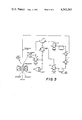
- FIG. 5 is a diagram of the air circuit for operating the instant invention.
- the present vehicle is generally shown at 10 and includes a body 12 of conventional semi-trailer dimensions which could be 45 ft. long, having a male coupling member 14 at its front end, and a female member 16 at its rear end to receive the male coupler of an adjacent body as at 18 to form a train for the railroad mode of operation, as seen in FIG. 2.
- the vehicle also includes a conventional kingpin 20 adjacent its front end for removable coupling to the fifth wheel of a tractor for the highway mode of operation, conventionally placed, telescoping semi-trailer landing gears 22, highway running gear 24 including tandem axles 26 (although a single axle suspension can be used) each axle mounting dual tired wheels 28, the running gear being suspended from the sub or underframe of the body towards the rear thereof by air-springs later to be described, the same constituting a highway wheel-set axle unit; and a railroad bogie or rail wheel-set axle unit 30, to be described in detail later, which includes a single axle 32 mounting a pair of flanged railroad wheels 34, at appropriate rail spacing transversely, the bogie being suspended by air-springs 36 from the vehicle body behind the highway running gear 24 and including a braking mechanism 38.
- a conventional kingpin 20 adjacent its front end for removable coupling to the fifth wheel of a tractor for the highway mode of operation, conventionally placed, telescoping semi-trailer landing gears 22, highway running gear 24 including tandem axle
- the air springs suspending the highway running gear may be inflated to lower the highway wheels 28 into engagement with a paved road while the air springs 36 of the railroad bogie are deflated so that the rail wheel-set axle unit or bogie may be raised into an elevated inoperative stored position as seen in FIG. 1, and by reversing this operation, the flanged railroad wheels 34 can be lowered to engage the track while the highway wheel-set axle unit is raised into an elevated inoperative stored position as shown in FIG. 2.
- the vehicle may be coupled as at 18 end to end to form a train to be pulled by a suitable locomotive.
- the rear sill structure shown in FIG. 4 includes a central casting 40 of generally "T" shape when viewed from the rear, a horizontal hole or slot terminating in an arcuate wall 42 adapted to receive the male coupling member extending from the front of an adjacent vehicle, a vertical bore 44 intercepting the slot adapted to receive a coupler locking pin and other parts required to accommodate the coupler pin and locking mechanism.
- a web member 46 Extending longitudinally from the casting 40 and secured thereto as by welding is a web member 46 shown here as a channel.
- the upper or top plate 48 which extends the full width of the vehicle and about 36 in. into the same is welded to the top of the channel member 46 through openings 50.
- a bottom plate 51 is provided which is substantially coextensive with the top plate 48 and which is spaced vertically therebeneath, the bottom plate being welded to the bottom of the central channel member 46 and to the bottom flanges of the side channel members 52 and to a vertical web member 49 at its forward edge.
- the top and bottom plates form, in effect, a sandwich between which are welded diagonal braces 54 and 56, the diagonal braces 54 being secured at their outer ends as at 58 to the casting 40.
- the bogie 30 which is shown in detail in FIG. 3 comprises a yoke 62 and a longitudinally extending tubular tongue 64 which is angulated so that its forwardly extending portion overlies and clears the highway wheel axles 26.
- the yoke comprises transversely spaced longitudinal forwardly extending side members 66 and 68, preferably of cast hollow rectangular configuration which are connected at their forward ends by a transversely extending tubular member 70.
- the tongue 96 is welded to the transverse tubular member of the yoke as at 72 centrally thereof.
- the member 70 mounts a suitable brake mechanism 38 for each railroad wheel.
- an arcuate tube 74 is secured to the running gear channels 76 and 78 of the vehicle extending transversely therebetween.
- the forward end of the tongue is provided with a split collar 80, retained by bolts.
- the bogie is allowed to self steer as the front end of the tongue is allowed to slide from side to side on the arcuate tube 74 so that the rail axle 32 is free to rotate about a vertical axis 82 at its center.
- the steering angle is limited by the length of the arcuate member 74 and is shown in phantom in FIG. 3 as 84.
- the arcuate tube 80 supplies the longitudinal restraint, and also the vertical restraint to the forces produced by the brake torque. It will be understood that the arcuate tube 74 may be of any suitable cross-section.
- FIGS. 4C and 4D where the lifting and retaining mechanism of the instant invention is shown in detail.
- a transverse tube 100 Rotatably mounted on the longitudinal running gear channels 76 and 78 on the underside of the vehicle body and above the cross tube 70 of the bogie yoke member 62 is a transverse tube 100.
- Welded to the tube 100 and rotatable therewith are a pair of transversely spaced downwardly extending hook members 102 with rearwardly extending hook ends 108.
- Welded to the cross tube 70 are transversely spaced pairs of lugs 104 which mount transversely extending shoulder bolts 106 between them engageable by the hook end 108 of each hook member 102.
- a mechanico-pneumatic brake chamber 128 Mounted as at 125 to the vertical web 49 of the rear sill structure of FIG. 4 of the vehicle underframe is a mechanico-pneumatic brake chamber 128.
- the chamber includes a diaphragm 127 and a spring 129 which is operatively connected to a threaded piston rod 130 upon which is secured a yoke 132 which mounts a pin 134 which is in turn secured to the arm 136 of a bell crank 138 which is fixed at its corner as at 140 to the rotatable tube 100, the other arm 142 of which also has a cam surface 144 which actuates a roller 146 which is connected to a roller-lever-operated 2-way valve 148 and which is also mounted as at 150 on the vertical web member 49.
- the action of the brake chamber 128 is such that when air is admitted into it behind the diaphragm 127, the spring 129 will be compressed and the push rod 130 will be extended whereas when air is removed from the chamber, the previously compressed spring will expand and retract the rod 130.
- the mode selector valve MSV In operation, to convert the vehicle from the rail mode to the highway mode, the mode selector valve MSV is moved first to a transfer position which actuates the quick release valve RV whereby air is vented from the rail air bags whereupon the vehicle body settles. This shortens the distance between the body and the bogie, i.e. between the tube 100 and cross tube 70, moving the operating rod from the phantom to the solid line position of FIG. 4C thereby opening height sensing valve 122, though in the rail to highway conversion this has no function.
- the hooks 102 are in their solid line position, being held there by the spring 129 in brake chamber 127 which is pulling the rod 130 urging the entire assembly consisting of bell crank 138, tube 100, and hooks 102 in a counter-clockwise direction.
- the hooks are cammed into a clockwise rotation until they can slide into an engaging position under bolts 106, rotating counter-clockwise under the urging of spring 129.
- valve 148 has its operating lines in the solid line position, it is open (allowing air to flow through), and as long as valve 122 has its operating arm 120 in the solid line position, it is also open. Air to inflate the rail air bags must flow through the "rail" supply line through feed valve FV to the levelling valves LV and thence to the air bags. However, as long as air pressure is present at the control port of feed valve FV, it remains closed, not permitting air to flow to the air bags. Since valves 122 and 148 are both open as long as hooks 102 are engaged, no air can flow to the air bags.
- the mode selector valve In the reverse conversion from the highway mode to the rail mode, the mode selector valve is moved from “highway” to "transfer”, causing deflation of the highway air bags allowing the body to settle until the railroad wheels are on the tracks.
- the mode selector valve is now moved to "rail" position directing air through the "rail" supply line to both the feed valve FV where it is momentarily blocked and to valve 122 from which it is delivered through valve 148 to the control port of FV and at the same time to brake chamber 127 which now pushes hooks 102 out of engagement with shoulder bolts 106 and simultaneously rotates cam surface 144 clockwise allowing valve 148 to close.
- control rod 118 and valve operating arm 120 go to the dotted line position, at which time valve 122 closes off its supply port and vents the chamber 127 to atmosphere allowing spring 129 to return bell crank 138 and hooks 102 to the solid line position, ready for the next cycle.
- S is supply
- D is delivery
- C is control and is exhaust.
- MSV is a 3-position, 6-way, lever-operated valve
- 122 is an adjustable position, 3-way, lever-operated valve
- 148 is a 2-position, 3-way, lever-operated valve
- LV is an adjustable position, 3-way, lever-operated valve
- FV is a 2-position, 2-way, pilot-operated valve
- RV is also a 2-position, 2-way, pilot-operated valve.
Landscapes
- Engineering & Computer Science (AREA)
- Transportation (AREA)
- Mechanical Engineering (AREA)
- Vehicle Body Suspensions (AREA)
Abstract
Description
Claims (13)
Priority Applications (1)
| Application Number | Priority Date | Filing Date | Title |
|---|---|---|---|
| US06/125,507 US4342265A (en) | 1980-02-28 | 1980-02-28 | Convertible rail-highway semi-trailer axle lifting and retaining mechanism |
Applications Claiming Priority (1)
| Application Number | Priority Date | Filing Date | Title |
|---|---|---|---|
| US06/125,507 US4342265A (en) | 1980-02-28 | 1980-02-28 | Convertible rail-highway semi-trailer axle lifting and retaining mechanism |
Publications (1)
| Publication Number | Publication Date |
|---|---|
| US4342265A true US4342265A (en) | 1982-08-03 |
Family
ID=22420038
Family Applications (1)
| Application Number | Title | Priority Date | Filing Date |
|---|---|---|---|
| US06/125,507 Expired - Lifetime US4342265A (en) | 1980-02-28 | 1980-02-28 | Convertible rail-highway semi-trailer axle lifting and retaining mechanism |
Country Status (1)
| Country | Link |
|---|---|
| US (1) | US4342265A (en) |
Cited By (8)
| Publication number | Priority date | Publication date | Assignee | Title |
|---|---|---|---|---|
| US4381713A (en) * | 1980-05-01 | 1983-05-03 | Bi-Modal Corporation | Convertible rail-highway semi-trailer air controlled braking and suspension shifting system |
| US4669391A (en) * | 1983-02-24 | 1987-06-02 | Railmaster System, Inc. | Train of highway trailers |
| US4841872A (en) * | 1985-06-03 | 1989-06-27 | Railmaster System, Inc. | Railway train of highway vehicles, and components therefor |
| US4869177A (en) * | 1988-03-28 | 1989-09-26 | Ferrosud S.P.A. | Rail-highway semitrailer |
| US4922832A (en) * | 1988-01-22 | 1990-05-08 | Strick Corporation | Intermodal road/rail transportation system |
| US4955144A (en) * | 1988-01-22 | 1990-09-11 | Strick Corporation | Compatible intermodal road/rail transportation system |
| GB2280644A (en) * | 1993-07-23 | 1995-02-08 | James Wallace Pollitt | Rail and road or water transport vehicle. |
| US20090238669A1 (en) * | 2008-03-18 | 2009-09-24 | Hathaway Richard C | Vehicle, system and method for handling cargo containers |
Citations (9)
| Publication number | Priority date | Publication date | Assignee | Title |
|---|---|---|---|---|
| US1938049A (en) * | 1932-02-11 | 1933-12-05 | Luella J Serrano | Road and rail vehicle |
| US2030311A (en) * | 1934-02-20 | 1936-02-11 | Kirwan Y Messick | Combined road and rail vehicle |
| US2039489A (en) * | 1933-03-15 | 1936-05-05 | Kirwan Y Messick | Transportation unit |
| US2889785A (en) * | 1955-11-23 | 1959-06-09 | Chesapeake & Ohio Railway | Road-rail vehicle |
| US2925791A (en) * | 1958-03-27 | 1960-02-23 | Chesapeake & Ohio Railway | Road-rail vehicle coupling and transfer mechanism |
| US3002469A (en) * | 1959-07-06 | 1961-10-03 | Gen Motors Corp | Suspension system for vehicle having alternate ground engaging wheel sets |
| US3286657A (en) * | 1963-08-13 | 1966-11-22 | Chesapeake & Ohio Railway | Railway-highway vehicle truck |
| US3342141A (en) * | 1965-05-03 | 1967-09-19 | Chesapeake & Ohio Railway | Convertible rail-highway vehicle truck |
| US4202277A (en) * | 1977-06-27 | 1980-05-13 | Bi-Modal Corporation | Convertible rail-highway semi-trailer |
-
1980
- 1980-02-28 US US06/125,507 patent/US4342265A/en not_active Expired - Lifetime
Patent Citations (9)
| Publication number | Priority date | Publication date | Assignee | Title |
|---|---|---|---|---|
| US1938049A (en) * | 1932-02-11 | 1933-12-05 | Luella J Serrano | Road and rail vehicle |
| US2039489A (en) * | 1933-03-15 | 1936-05-05 | Kirwan Y Messick | Transportation unit |
| US2030311A (en) * | 1934-02-20 | 1936-02-11 | Kirwan Y Messick | Combined road and rail vehicle |
| US2889785A (en) * | 1955-11-23 | 1959-06-09 | Chesapeake & Ohio Railway | Road-rail vehicle |
| US2925791A (en) * | 1958-03-27 | 1960-02-23 | Chesapeake & Ohio Railway | Road-rail vehicle coupling and transfer mechanism |
| US3002469A (en) * | 1959-07-06 | 1961-10-03 | Gen Motors Corp | Suspension system for vehicle having alternate ground engaging wheel sets |
| US3286657A (en) * | 1963-08-13 | 1966-11-22 | Chesapeake & Ohio Railway | Railway-highway vehicle truck |
| US3342141A (en) * | 1965-05-03 | 1967-09-19 | Chesapeake & Ohio Railway | Convertible rail-highway vehicle truck |
| US4202277A (en) * | 1977-06-27 | 1980-05-13 | Bi-Modal Corporation | Convertible rail-highway semi-trailer |
Cited By (8)
| Publication number | Priority date | Publication date | Assignee | Title |
|---|---|---|---|---|
| US4381713A (en) * | 1980-05-01 | 1983-05-03 | Bi-Modal Corporation | Convertible rail-highway semi-trailer air controlled braking and suspension shifting system |
| US4669391A (en) * | 1983-02-24 | 1987-06-02 | Railmaster System, Inc. | Train of highway trailers |
| US4841872A (en) * | 1985-06-03 | 1989-06-27 | Railmaster System, Inc. | Railway train of highway vehicles, and components therefor |
| US4922832A (en) * | 1988-01-22 | 1990-05-08 | Strick Corporation | Intermodal road/rail transportation system |
| US4955144A (en) * | 1988-01-22 | 1990-09-11 | Strick Corporation | Compatible intermodal road/rail transportation system |
| US4869177A (en) * | 1988-03-28 | 1989-09-26 | Ferrosud S.P.A. | Rail-highway semitrailer |
| GB2280644A (en) * | 1993-07-23 | 1995-02-08 | James Wallace Pollitt | Rail and road or water transport vehicle. |
| US20090238669A1 (en) * | 2008-03-18 | 2009-09-24 | Hathaway Richard C | Vehicle, system and method for handling cargo containers |
Similar Documents
| Publication | Publication Date | Title |
|---|---|---|
| US4202454A (en) | Coupler to connect convertible rail-highway vehicles end to end | |
| US4202277A (en) | Convertible rail-highway semi-trailer | |
| US5103740A (en) | Vehicle for road and rail operation with air suspension for adjusting weight on both the road wheels and rail wheels | |
| US4202276A (en) | Self-steering wheel-set for convertible railway vehicle | |
| US4316418A (en) | Convertible rail highway semi-trailer air controlled suspension shifting system | |
| US4917020A (en) | Transition vehicle for use with convertible rail-highway trailers | |
| US5868078A (en) | Road and rail vehicle using rail wheel drive and apparatus | |
| US4342264A (en) | Convertible rail-highway semi-trailer fluid suspension | |
| US4381713A (en) | Convertible rail-highway semi-trailer air controlled braking and suspension shifting system | |
| US6460468B1 (en) | Intermodal transport system | |
| EP0450942B1 (en) | Locking mechanism on a vehicle | |
| US4448132A (en) | Convertible railway-highway vehicle | |
| US4955292A (en) | Dual-mode rail-highway semi-trailer with separable bogie | |
| EP0642428B1 (en) | Convertible railway-roadway vehicle and method of use | |
| US4311244A (en) | Automatic coupler to connect convertible rail-highway vehicles end to end | |
| US4342265A (en) | Convertible rail-highway semi-trailer axle lifting and retaining mechanism | |
| US2058955A (en) | Appliance for the transport of railway cars on streets | |
| US6786158B2 (en) | Railcar-moving vehicle with load-shifting device | |
| US3762337A (en) | Railed vehicle-carrier system | |
| US5619931A (en) | Road and rail using rail wheel drive and apparatus | |
| EP1539513B1 (en) | A vehicle adapted for different driving modes, and a method of driving such vehicles | |
| US2844108A (en) | Trailer train | |
| US5601030A (en) | Railraod bogie, for connecting vehicles in an articulated train | |
| US4981083A (en) | Dual-mode rail-highway semi-trailer | |
| US3356042A (en) | Convertible rail-highway vehicle |
Legal Events
| Date | Code | Title | Description |
|---|---|---|---|
| STCF | Information on status: patent grant |
Free format text: PATENTED CASE |
|
| AS | Assignment |
Owner name: FIRST NATIONAL BANK OF CHICAGO, THE, FIRST NAT'L. Free format text: SECURITY INTEREST;ASSIGNOR:BI- MODAL CORPORATION A CORP OF CT;REEL/FRAME:004172/0479 Effective date: 19830908 Owner name: FIRST NATIONAL BANK OF CHICAGO, THE, ILLINOIS Free format text: SECURITY INTEREST;ASSIGNOR:BI- MODAL CORPORATION A CORP OF CT;REEL/FRAME:004172/0479 Effective date: 19830908 |
|
| AS | Assignment |
Owner name: NORTH AMERICAN CAR CORPORATION, Free format text: RELEASED BY SECURED PARTY;ASSIGNOR:FIRST NATIONAL BANK OF CHICAGO;REEL/FRAME:004500/0422 Effective date: 19851231 |
|
| AS | Assignment |
Owner name: CHAMBERLAIN GROUP, INC., THE Free format text: MERGER;ASSIGNORS:CHAMBERLAIN GROUP, INC., THE, A DE CORP. (INTO);CHAMBERLAIN OF CONNECTICUT, INC., A CT CORP. (CHANGED TO);REEL/FRAME:004709/0685 Effective date: 19860801 Owner name: CHAMBERLAIN OF CONNECTICUT, INC. Free format text: CHANGE OF NAME;ASSIGNOR:BI-MODAL CORPORATION, THE;REEL/FRAME:004706/0044 Effective date: 19860321 |
|
| AS | Assignment |
Owner name: WABASH NATIONAL CORPORATION, INDIANA Free format text: ASSIGNMENT OF ASSIGNORS INTEREST.;ASSIGNORS:CHAMBERLAIN GROUP, INC., THE;RAILMASTER SYSTEM, INC.;REEL/FRAME:005861/0631 Effective date: 19910529 |
|
| AS | Assignment |
Owner name: WABASH NATIONAL, L.P., INDIANA Free format text: ASSIGNMENT OF ASSIGNORS INTEREST;ASSIGNOR:WABASH NATIONAL CORPORATION;REEL/FRAME:010804/0743 Effective date: 19991028 |
|
| AS | Assignment |
Owner name: WABASH TECHNOLOGY CORP., ILLINOIS Free format text: ASSIGNMENT OF ASSIGNORS INTEREST;ASSIGNOR:WABASH NATIONAL, L.P.;REEL/FRAME:010742/0238 Effective date: 19991028 |