-
This application is a continuation-in-part of Application Serial Number
09/255,204, filed on February 22, 1999 and is based on provisional patent application Serial No.
60/189,578, filed on March 15, 2000.
BACKGROUND
-
The present invention relates generally to rail cars for an integral/semi-integral
intermodal train employing a segmented roll-on/roll-off system. More particularly, the rail cars
can be connected together to form segments of an integral train for carrying freight, such as
semi-trailers, wherein each train segment has an integrated arrangement composed of different
types of rail car platforms, including an adapter platform, intermediate platforms and a loading
ramp platform. The present invention relates, in particular, to an apparatus for the automatic
application and release of parking brakes for the rail cars. An intermodal train platform system
is described in applicants co-pending application Serial No. 09/252,204 filed February 22, 1999,
which is hereby incorporated by reference herein in its entirety.
SUMMARY
-
Adapter, intermediate and ramp platform rail car platforms are provided for
forming an intermodal train for carrying standard over-the-highway semi-trailers. The
intermodal train can have a standard locomotive pulling one or more identical train segments.
Each segment can have eleven or more platforms and may be loaded or unloaded independently
of any other segment using a self contained, roll-on/roll-off system. This system can have an
integral ramp on at least one end of each segment, for use by a hostler tractor and/or the semi-trailers
as they are being loaded or unloaded. The platforms which make up each segment can be
connected by articulated joints so as to eliminate longitudinal slack and reduce costs. At least
one platform should be equipped with a standard knuckle coupler at standard height to permit the
segments to be pulled by any existing locomotive.
-
In order to permit carriage of non-railroad trailers, a very good ride quality is
required; and this can be provided by premium trucks and a low 36 ½ inch deck height, both of
which combine to permit stable operation at high speed. High speed operation is also made
possible by a brake system providing actual train average braking ratios of eighteen percent
nearly double that available with standard equipment. Use of this braking system can permit the
Steel Turnpike to operate at speeds thirty percent higher than AAR standard freight trains, while
stopping within the same distance.
-
Several sub-systems intended to speed performance and enhance reliability can be
provided on each segment. These are the "Electronic Assisted Air Brake," "Health Monitoring"
and "Trailer Tie-Down" subsystems. A "Locomotive Interface Unit" subsystem is also required
if former subsystems are to be used to best effectiveness.
-
In a preferred embodiment of the present invention a spring applied, air released
parking brake is provided for the intermodal train. The parking brake is only permitted to apply
when normal air brake cylinder pressure is lost, and preferably only to a degree approximating
the loss of normal full service brake cylinder pressure. Manual release of the parking brake is
provided should it become necessary or desirable to move a rail car without first charging the
brake pipe.
-
Other details, objects, and advantages of the invention will become apparent from
the following detailed description and the accompanying drawing Figures of certain
embodiments thereof
BRIEF DESCRIPTION OF THE DRAWINGS
-
A more complete understanding of the invention can be obtained by considering
the following detailed description in conjunction with the accompanying drawings, wherein:
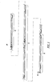
- Figure 1 is a side view of a presently preferred embodiment of an intermodal train
segment
- Figure 2 is an enlarged side view of an embodiment of an adapter platform for the
intermodal train shown in Figure 1.
- Figure 3 is a top view of the adapter platform shown in Figure 2.
- Figure 4 is an end view of the adapter platform shown in Figure 2.
- Figure 5 is a section view taken along the line V-V of Figure 3.
- Figure 6 is a side view of the intermediate platform shown in Figure 1.
- Figure 7 is a top view of the intermediate platform shown in Figure 6.
- Figure 8 is a section view taken along the line VIII-VIII in Figure 7.
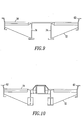
- Figure 9 is a section view taken along the line IX-IX in Figure 7.
- Figure 10 is a section view taken along the line X-X in Figure 7.
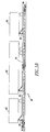
- Figure 11 is a side view of the ramp platform shown in Figure 1.
- Figure 12 is a top view of the ramp platform shown in Figure 11.
- Figure 13 is a side view partially in section of Figure 11 showing the ramp in a
lowered position.
- Figure 14 is an end view of the ramp platform shown in Figure 11 with the ramp
raised.
- Figure 15 is an enlarged view of the section view in Figure 5.
- Figure 16 is a sectional view through line XVI-XVI in Figure 3.
- Figure 17 is an enlarged view of the section view in Figure 9.
- Figure 18 is a side view of the intermodal train segment in Figure 1 showing a
random loading arrangement of trailers.
- Figure 19 is a side view partially in section of the B-end of either the adapter
platform or intermediate platform illustrating the connections of the side cells to the center cell to
resist vertical bending.
- Figure 20 is a top view partially in section of the B-end of the platform shown in
Figure 19.
- Figure 21 is a perspective view, partially in section, showing the interleaved deck
structure.
- Figure 22 is a side view partially in section of the B-end of a ramp platform and
showing an embodiment of a coupler with the ramp in the raised position.
- Figure 23 is the same figure shown in Figure 22 except showing the ramp in the
lowered positioned.
- Figure 24 is a side view partially in section of the B-end of a ramp platform
showing a different embodiment of a coupler member.
- Figure 25 is the same view as Figure 24 except showing the ramp in a raised
position.
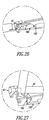
- Figure 26 is a close up view of the coupler in a lowered position as shown in
Figure 24.
- Figure 27 is a view similar to Figure 26 except showing the ramp in a raised
positioned wherein the coupler is projecting beyond the end of the ramp platform.
- Figure 28 is a side view partially in section of a jointed ramp member attached to
the end of the ramp platform.
- Figure 29 is the same view as in Figure 28 except showing the ramp in a position
intermediate between the lowered and raised positions.
- Figure 30 is the same view as in Figure 29 except showing the ramp in a fully
retracted position.
- Figure 31 is a top view, partially in section, of the ramp and ramp platform shown
in Figure 28.
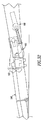
- Figure 32 is a more detailed view of the ramp attachment and coupler in Figure
28.
- Figure 33 is the same view as Figure 32 except showing the ramp in a fully
retracted position with the coupler extending beyond the end of the platform.
- Figure 34 is a schematic of a first embodiment of a brake system for an
intermodal train.
- Figure 35 is a schematic diagram of a first embodiment of a spring applied
parking brake control.
- Figure 36a is a top view of a truck equipped with the spring applied parking brake
shown in Figure 34.
- Figure 36b is an end view of the truck shown in Figure 36a.
- Figure 37a-37e are position diagrams showing the operation of the spring applied
air brake shown in Figures 34 and 35.
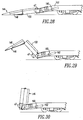
- Figures 38a-38c are more detailed, side views, of the operating positions of the spring applied parking brake.
- Figure 39 is an end view of the spring applied brake shown in Figure 37b.
- Figures 40a and 40b show a top and side plan view, respectively, of a preferred
embodiment of the spring applied, air released parking brake of the present invention.
- Figure 41 shows a detailed view of the compensation lever and an actuator lever
shown if Figure 40a.
- Figures 42 and 43 show compensating positions of the parking brake
configuration as a train moves along curved sections of track
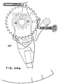
- Figures 44a - 44f are schematic representations of an emergency manual release
mechanism according to the present invention.
- Figures 45a - 45c are simplified representations of the operation of the parking
brake according to the present invention
- Figure 46 shows a preferred embodiment of an escutcheon plate used to indicate
and limit handle position and function to an operator for the present invention.
- Figure 47 shows an alternate embodiment of the spring applied, air released
parking brake of the present invention in a manually released, no air on car position.
- Figure 48 shows the embodiment of the spring applied, air released parking brake
of the present invention in Figure 47 showing the automatic parking brake function restored by
normal recharge of the brake system.
- Figure 49 shows a top view of the a release device linkage and bell crank for the
spring applied, air released parking brake shown in Figure 47.
- Figure 50 show an eight platform articulated train having an automatic spring
applied parking brake according to the present invention.
- Figure 51 is a schematic representation of air piping utilized for the spring applied
parking brake.
- Figure 52 is a schematic representation of a control system for the spring applied
parking brake.
- Figure 53 is an alternative embodiment for an escutcheon plate according to an
alternative embodiment of the spring applied parking brake.
- Figure 54 is a pneumatic diagram for the alternative spring applied parking brake.
- Figure 55 is a schematic diagram similar to Figure 34 but showing a preferred
embodiment of an electrical communication scheme for a train health monitoring system.
-
DESCRIPTION OF CERTAIN PREFERRED EMBODIMENTS
-
A semi-integral, intermodal train segment 40, intended to carry standard over-the-highway
(non-AAR) semi-trailers is shown in Figure 1. An intermodal train may consist of a
standard locomotive pulling one or more identical train segments 40. Each segment 40 includes
at least three, and preferably eleven or more platforms 43, 44, 45 and may be loaded or unloaded
independently of any other segment 40 using a self contained, roll-on/roll-off system. This
system includes an integral ramp 46 on an end ramp loader platform 45 of each segment 40, for
use by the special hostler tractor and the semi-trailers as they are being loaded or unloaded. The
platforms 43, 44, 45 which make up each segment 40 are connected by articulated joints so as to
eliminate longitudinal slack and reduce costs, but at least one platform is equipped with a
standard knuckle coupler 47 at standard height to permit the segments to be pulled by any
existing locomotive. No terminal infrastructure is required other than an area at least 75 feet
long, whose surface is graded to approximately the height of the top of rail. Such a system is
also generally referred to as the Steel Turnpike.
-
in order to permit carriage of non-railroad trailers, a very good ride quality is
required; and this can be provided by premium trucks and a low 36 ½ inch deck height, both of
which combine to permit stable operation at high speed. High speed operation is also made
possible by a brake system providing actual train average braking ratios of eighteen percent
nearly double that available with standard equipment. Use of this braking system permits the
Steel Turnpike to operate at speeds thirty percent higher than AAR standard freight trains, while
stopping within the same distance. High speed operation is worthless in the service sensitive
trailer market, however, if extremely high reliability is not possible. In order to provide this
reliability, a continuously operating health monitoring system is provided. This system signals
potential problems to the operator as soon as they arise, thus permitting timely maintenance to
correct defects that would otherwise cause delays, damage or equipment out-of-service
problems. The continuous monitoring system is capable of absolutely eliminating two of the
most significant causes of derailment, namely broken wheels and burned off journal bearings.
-
It is envisioned that such intermodal trains will normally consist of several
segments 40 to produce trains 40 of over one hundred trailer capacity. In operation, it can be
advantageous to use the segments 40 in pairs with two ramp platforms 45 connected to each
other end-to-end, as will be further described.
-
Each intermodal train segment 40 includes three platform types 43, 44, 45,
articulated together. Each end of each platform type is, for purposes of description, assigned one
of two names, referred to previously as the A-end and the B-end. The forward end of such
platform will be referred to as the A-end while the rearward end will be called the B-end. The
first of the three types of platforms is the adapter platform 43, which is shown in more detail in
Figures 2-5. The adapter platform 43 has a 28 inch low conveyance truck 48, a conventional
knuckle coupler 46, hydraulic draft gear 49, standard carbody bolster 60 shown best in Figure 15,
and a centerplate 61 at the A-end. At the B-end, the adapter platform 43 has a 33 inch truck 51
with high capacity bearings and a female half spherical articulated connector 50 with combined
center plate, which can be a standard Cardwell SAC-1 type connector. The adapter platform 43
is intended to be coupled behind a standard locomotive. The construction of the carbody bolster
28 inch truck 48 mounting at the A-end is shown in more detail in Figure 15, and is more fully
described in connection with that figure. Similarly, the structure of the B-end is shown in more
detail in Figure 16 and is described more fully in connection with that figure.
-
The second platform type is the intermediate platform 44, shown in Figure 3, also
having a female articulated (SAC-1) connection 50 and a 33 inch truck 51 at its B-end which is
identical to the truck 51 on the B-end of the adapter car 43. A male articulated connection 52
without a truck is provided at the A-end of the intermediate platform 44. The A-end is of the
intermediate platform 44 is supported by the mating female articulation connector 50 and truck
51 at the B-end of an adjacent platform.
-
The third type platform is the ramp loader platform 45, shown in Figures 11-14.
The ramp platform 45 is similar to the intermediate platform 43 in that it too has a truck 48 only
at the B-end. However, the truck 48 at the B-end of the ramp platform 45 differs in that a 28
inch low conveyance type truck 48, as on the adapter platform 43, is used. Since this truck 48
supports only about half the weight borne by the 33 inch trucks 51 of the intermediate platforms
43, the wheels can be smaller without danger of overloading the wheels, axles or bearings. The
A-end of the ramp platform 45 also has a male articulated connection 52 which is supported by
the truck 51 at the B-end of an adjacent platform, in like manner as the intermediate platforms
44, and mates with a female articulated connector 50. At the B-end of the ramp platform 45, the
deck 54 has an extended, sloped portion 56 which protrudes beyond the truck 48, and is
supported by a conventional carbody bolster 60 and centerplate rather than an articulated
connection. Use of the 28 inch truck at this location allows the deck 56 height of the end of the
ramp platform 45 to be reduced from the 36 ½ inch height of the other platforms 43, 44 down to
31 ½ inches at the B-end truck centerline of the ramp platform 45. Consequently, the height that
the loading ramp 46 must rise to allow roll-on loading can be significantly reduced. This height
is further reduced between the truck centerline and the ramp platform end sill by angling the
sloped portion 56 toward the ground, resulting in a final deck height at the end sill of only 17¼
inches. This low height is easily reached by a short, lightweight ramp assembly 46 which is
hinged to the ramp platform 45 end sill. The ramp can be raised to a stored position for travel, or
lowered to a loading position by a ramp positioning device, such as, for example, an air cylinder
under the control of an attendant at the terminal.
-
Since the B-end of the ramp platform 45 is so much lower than the normal 34½
inch coupler height, an unconventional coupler arrangement is required, particularly if the ramp
platform 45 is to be coupled to a conventional locomotive or car. Presently, there are two
preferred configurations, shown in Figures 22-27. One configuration, shown in Figures 24-27,
uses a standard knuckle coupler 47 carried in an elevating draft gear 49, similar in concept to the
retractable couplers used on passenger train locomotives through the 1950's. The other
configuration, shown in Figures 22-23 and 28-33, is useful if, in operation, the ramp platform 45
is only to be coupled to a similar ramp platform 45 of a different train segment 40. In this latter
case, a simple rapid transit type coupler 107 carried well below the normal 34 ½ inch height will
suffice. Both constructions are described in more detail below in connection with Figures 22-33.
-
Several unique sub-systems, intended to speed performance and enhance
reliability are provided on each segment. These include an Electronic Assisted Air Brake, Health
Monitoring, and Trailer Tie-Down subsystems. A locomotive interface system is also required if
these are to be used to best effectiveness. A brief description of each sub-system is included
below, as well as more detailed descriptions of each of the three platform types.
Platform Types
-
Each platform can have the same basic structure except for the ends. The
intermediate platform 44 can serve as the "standard" platform from which the adapter and ramp
platforms can be created. The economics are thus greatly improved because the standard
platform can be mass produced and the other two platforms can be constructed simply by
modifying the ends of the standard platform. For example, the adapter platform 43 is
constructed by basically cutting the A-end off an intermediate platform 44 and welding on the
modified A-end of an adapter platform 43. In Figure 2, a splice line 110 indicates generally
where the A-end of the intermediate platform 44 is cut off and the A-end configuration of the
adapter platform 43 is welded on.
-
Referring to Figure 11, another splice line 112 indicates generally where the B-end
of the intermediate platform 44 is cut off for the attachment of the B-end configuration for
the ramp platform 45. Making the intermediate platform 44 the "standard" makes sense because
each segment 40 of the intermodal train has preferably at least nine intermediate platforms 44
and only one each of the adapter 43 and ramp 45 platforms.
Adapter Platform
-
The adapter platform 43, as mentioned, has one conventional knuckle coupler 47
on its A-end, and one truck at each of the A- and B-ends. The coupler 47 is carried by a 15 inch
travel "buff only" hydraulic draft gear 49, while the trucks proposed are both of the swing
motion type. The A-end truck 48 is a 28 inch low conveyance model with normal seventy ton
bearings and axles, while the B-end truck 51 is a 33 inch wheel model equipped with oversize
bearings. These trucks 48, 51 provide improved ride and tracking characteristics as compared to
a standard three-piece truck. Constant contact "teks pac" type side bearings are proposed in
order to control truck hunting at high speed. Use of this type truck is required if conventional
(non-AAR) trailers are to be carried, because general service trailers should not be lifted, have
softer springs and lack the longitudinal strength specified by AAR for conventional piggyback
service.
-
An enlarged cross sectional view of the construction of the carbody bolster 60 and
28 inch truck 48 mounting at the A-end is shown in Figure 15, while Figure 16 shows a similar
view taken at the B-end. Figure 16 illustrates the unique construction of the platform over the B-end
33 inch trucks 51 which is common to all of the intermediate platforms 44. Of particular
importance is the fact that there is no carbody bolster 60 over the truck side frame 63. This
allows the deck 54 to be brought down to the desired height with only a minimum deck thickness
above the side frame 63, as shown in Figure 16.
-
The A-end of the adapter car 43 uses a conventional carbody bolster 60 and center
plate 61 as well as the previously mentioned 15 inch hydraulic draft gear 49 and F-type knuckle
coupler 47. Use of this draft gear 49 is recommended because of the slack-free nature of the
segment 40 and is particularly important when coupling to a locomotive or conventional
equipment, as the long articulated train structure would otherwise act as a huge single mass, and
if coupled to at any but the lowest speed, could cause damage to the couplers and other parts of
the conventional equipment.
-
The deck 54 of each platform 43, 44, 45 is preferably made from steel gratings 70
suppoded by formed gussets 72 running from the center sill 73 of the platform to the side sills
62, as shown best in Figure 17. The side sills 62 are formed channels and are set above the
height of the deck 54 so as to provide curbs which aid in preventing a trailer from being
inadvertently pushed off of the deck when backing into loading position.
-
The use of grating 70 for the deck 54 is aimed primarily at making the deck 54
self-clearing of snow and ice, as precipitation dropping on it can simply fall through to the rail or
track bed below and need not be removed by snow blowers, plows or other apparatus. The
center sill 73 is not a conventional AAR construction, but instead is constructed from a wide box
beam, open at the bottom and fabricated with relatively light weight webs 75, and having a top
plate 74 and bottom flanges 76 of differing thickness along the length of the structure so as to
properly resist vertical bending, which is maximum at the center. This "tapered flange"
approach reduces weight where bending stresses are not as high. Use of a relatively thin web 75
could allow buckling, but this is prevented by reinforcing the webs 75 by welding the grating
support gussets 72 to the full height of the webs 75, as shown in Figure 17.
-
The top of the center sill 73 is also used to support the legs of the folding or "pull-up"
hitches 80 which are used to secure the nose of a trailer 82 to the deck 54 by attaching to the
trailer's king pin. These hitches are well known in the railway industry, but a modified version
is used on the steel turnpike because the platforms will never be humped, thus sparing the design
the extreme longitudinal forces imposed by trainyard impacts during switching operations. Two
such hitches are secured to the outer sill 73, one near the B-end and another 29 feet away, near
the center of the platform. This hitch spacing permits any presently legal trailer 82, including the
extra long 57 foot trailers (legal in only 5 western states), to be efficiently carried. At the same
time, the 29 foot hitch spacing allows 28 foot long "pup" trailers 83 to be loaded with only a one
foot separation between nose and tail. Likewise, as shown in Figure 18, any combination of
trailers 82, 83 can be carried, loaded in random order, with long trailers 82 spanning the
articulation if necessary.
-
The articulating connection is essentially identical at all articulated joints between
each platform. At the B-end of the adapter 43 and ramp 44 platforms, upper side bearings 66 are
provided to transfer any roll of the platform into the truck bolster and suspension system.
Constant contact side bearings are preferably used on the truck bolster in order to both minimize
carbody roll relative to the bolster, and to add rotational damping to the truck 51 as an aid to
controlling truck "hunting" during high speed operation. Figure 16 shows the upper 66 and
lower 68 side bearing set up, and it can be seen that, unlike normal car building practice, there is
no carbody bolster 60 extending beyond the side bearings 66, 68. It is this bolsterless
construction that permits the 37 inch deck height, as use of a carbody bolster 60 would add the
thickness of this part to the minimum clearance above the truck side frame 63 that is used.
-
At the B-end side sills, a roll stabilizer bearing shelf 90 is provided which can
withstand high vertical loads. This bearing shelf 90 cooperates with a bearing shoe 92 on the A-end
side sills 62 of an adjacent platform 44. This construction, shown best in Figure 16, results
in a roll stabilizer bearing which essentially connects adjacent decks 54 torsionally, which will
greatly reduce carbody roll on less than perfect track. This is particularly important where
trailers 82 are being carried bridging an articulated joint, because this construction reduces
racking of the trailer 82 that relative roll could otherwise induce.
-
Near the B-end of the adapter 43 and intermediate 44 platforms, but inboard of
the truck, are a pair of structural connections 94 extending from the left side sill 62 to the left
side of the center sill 73 to the right side of the center sill 73 and thence to the right side sill 62,
as shown in Figures 19 and 20. These connections 94 are made up of the two cross connections
94 and the center sill 73 top cover plate 74 and provides the necessary vertical load carrying
capacity to the side sills 62 as would be given by the carbody bolster 60 connection in a
conventional carbody construction, but without introducing the additional height of the
conventional carbody bolster 60 as previously discussed. That is, these connections 94 support
the ends of the side sills 62 and transmit vertical side sill 62 loads into the center sill 73.
-
An interleaved deck structure, shown best in Figure 21, is preferably provided
where the decks 54 of each articulated platform 43, 44, 45 mate. For example, as shown, at the
deck connection of the adapter platform 43 to the first intermediate platform 44, the deck
structure 54 is interleaved with its mate in such a way that when the segment 40 rounds a curve
there is no scraping of one platform's deck 54 on top of the other, as would be the case for a
conventional bridge plate left in the lowered position. An advantage of interlacing the deck end
structures in this manner, which is common at all the articulations, is that an uninterrupted
platform is provided from end to end of the entire segment, which has been shown to greatly
speed the loading process. As shown, the B-end of the deck 54 has a slotted curvature 97 near
each side sill 62 into which can be received a correspondingly curved extension 99 of the A-end
of an adjacent deck 54 when the articulated platforms round a curve.
-
Referring back to Figure 16, the construction at the A-end of the adapter platform
43, is more conventional in that it does have a carbody bolster 60, stub AAR center sill 64, a
center plate 61 and draft gear attachments 49. Unlike the intermediate 44 and ramp 45 platforms,
however, the adapter platform 43 A-end supports only one end of one platform, thus carrying
much less weight than the other trucks 51. This permits the use of the 28 inch diameter wheel
truck 48 under the A-end which provides an additional 5 inches over the truck frame 63 and
permits the application of the aforementioned wide box beam center sill 73.
-
One other feature of the adapter platform 43 is that it permits the use of a 36 inch
high bulkhead 86 at the A-end which would prevent driving a trailer off platform end of the car
in the event of operator error.
Intermediate Platform
-
The intermediate platform 44, shown in Figures 6-8, shares almost all of the
features above described, except that it has a truck 51 at the B-end only, and the center sill 73
connection to the side sills 62 is essentially identical at both ends. The A-end of the center sill
73 carries a male articulation joint connector 52. The articulated joint proposed, Cardwell
Westinghouse SAC-1 type, is designed to take the weight of the platform 44 from the male half
52 into the female half 50 at the B-end of an adjacent platform and thence down into the truck 51
associated with the female connector 50.
-
Additionally, the A-end has the aforementioned bearing shoes 92 and the B-end
has the bearing shelves 90. The side bearings 66, 68 of the truck 51 are used to steady the B-end
of the intermediate platform 44 against roll motion, and the bearing shelves 90 cooperate with
the bearing shoes 92 on the A-end of an adjacent platform, in the manner same described for the
adapter platform 43, to provide roll stability. This coupling of adjacent platform side sills 62
results in the stabilizing of the A-end of the intermediate platform 44 by the B-end of an adjacent
platform. This, of course, implies that the B-end of the intermediate platform 44 is stabilized in
roll by the side bearings 66, 68 of an associated truck, which is insured by using constant contact
side bearings.
-
Any number of intermediate platforms 44 may thus be assembled into a segment
40 with one adapter platform 43 at the head and one ramp platform at the tail. A presently
preferred intermodal train segment 40 would consist of 11 platforms, namely, one adapter
platform 43, 9 intermediate platforms 44, and 1 ramp platform 45. This particular combination is
preferred primarily to achieve economy in the braking system and easy interchangeability of
intermediate platforms 44 in groups of three within a segment 40, so as to produce longer or
shorter segments, or effect repairs without unduly withdrawing equipment from service.
Ramp Loader Platform
-
The ramp platform 45, shown in Figures 11-13, is very similar to the intermediate
platform 44 in that it has a truck 48 only at the B-end and depends on the sliding connection of
the side sills 62 to provide roll stability at the A-end. The aforementioned sliding connection
being the frictional engagement of the bearing shoes 92 on the A-end of the ramp platform 45
with the bearing shelves 90 on the B-end of an adjacent platform 44.
-
Referring to the drawing, the B-end employs a 28 inch wheel diameter truck 48 in
a similar manner as the A-end of the adapter platform 44, but does not have a carbody bolster.
The lower deck height at the 28 inch truck 48 is instead used to reduce the deck height at the B-end
below 32 inches by sloping the length of the ramp platform 45 from 37 inches at the A-end
down to 32 inches at the B-end. The ramp platform 45 is otherwise identical to the adapter 43
and intermediate 44 platforms.
-
The reduction in deck height at the end of the ramp platform 45 where the ramp
46 is attached reduces the length of ramp 46 necessary to climb from ground level to the deck.
This length can be further reduced by sloping an extended portion 56 of the deck downward
beyond the B-end truck, at the same slope as the ramp 46 will use (approximately 1 in 8) by
lowering the end of the ramp platform 45 at its attachment point to the ramp 46. The length, and
hence the weight, of the ramp 46 are greatly reduced by this technique, thus allowing
simplification of the ramp lifting and stowing mechanism.
-
As a result, the deck height at the B-end of the ramp platform 45 is only 17¼
inches above top of the rail at the end sill. Hinged to the car structure at this point is the loading
ramp 46 which has a length of only about 10 feet 3⅝ inches. This short ramp length can be
efficiently counterbalanced throughout its operating angle of over 90 degrees by the use of a
spring tensioning device 160, shown in Figures 22-33, mounted on the end of the ramp platform
45. At the full up position, the center of gravity of the ramp 46 is slightly inboard of its pivot
points, thus the lever arm is negative and the ramp 46 is producing a torque which would fold it
back onto the ramp platform 45. At this point, however, positive stops provided on the ramp 46
sides prevent further folding and hooks, provided adjacent to the stops, can be manually engaged
so that the ramp 46 cannot be pulled down until the hooks are manually released.
-
Operating in parallel with the spring balance mechanisms just described is an air
cylinder 162. When the retaining hooks mentioned above have been manually released, air can
be introduced into this cylinder 162 to overcome the torque caused by the small negative lever
arm and start the ramp 46 down. Once this has occurred, the unbalanced portion of the weight of
the ramp 46 will tend to pull the piston out of the cylinder 162 and unfold into its loading
position. The speed of this operation can be easily controlled by choking the exhaust of air from
the rod end of the cylinder 162. Air for operation of the cylinder 162 can be supplied from a
dedicated reservoir charged by main reservoir equalizing pipe when the train is coupled. This
reservoir can be sized to permit at least two operations of the ramp 46 from an initial charge of
130 psi. Provision is also preferably made to take air from a hostler tractor for this operation
without requiring the hostler to charge any other part of the train's pneumatic system.
-
The force pulling on the air cylinder piston 162 during the ramp 46 lifting
operation could be made either positive or negative. That is to say, the ramp 46 could be
designed to be either slightly overbalanced or slightly underbalanced by the spring and cam
mechanism 160. Underbalance is preferred as it would allow manual lowering of the ramp 46 in
an emergency situation where air was not available for its operation. Likewise, underbalance
would prevent the nose of the ramp 46 from bouncing as trailers are rolled up on it.
-
As shown best in the more detailed view of the same platform coupler mechanism
in Figures 22 and 23, when the ramp 46 is up, the coupler pulling faces extend beyond the actual
ramp 46 position so as to prevent interference between the end of the ramp platform 45 and
whatever platform it is coupled to. Thus, the ramp end of the platform 45 may be coupled to
another ramp platform 45 with no difficulty. Further, if rapid transit type couplers 107 as shown
in the drawing are used, this coupling can also effect electrical and air connections.
-
Two coupler connections are possible. The first, as shown in Figures 22-23 and
28-33, uses a transit type coupler 107 at a 20 inches height and would be a very straight forward
application, but would not permit the ramp platform 45 end of a segment 40 to be pulled by
conventional equipment without some sort of adapter. An alternative coupler connection shown
in Figures 24-27, uses a standard knuckle coupler 47 and can carry it at standard coupler height.
In both cases a retractable coupler is preferably used.
-
Referring back to Figures 22 and 23, after the ramp 46 has been swung up, the
coupler's elevating mechanism 170 will be operated by the lifting of the ramp 46 and the linkage
shown swings the coupler 107 up into operating position. It should be noted that while the
coupler 107 is supported from below by the elevating mechanism 170, the flat faces of the two
transit couplers will, when brought together, lift their heads a further half inch or so, so as not to
have wear and interference between the elevating mechanism 170 and the mated couplers 107
when the train is traveling at speed.
-
In the alternative coupler 47 shown in Figures 24-27, a much more elaborate
elevating mechanism 180 is needed because both the coupler 47 and draft gear 49 must be
elevated to the standard 34 ½ inch height. This method permits coupling to conventional
equipment with no adapter. This standard coupler 47, while more universal, would not be
particularly advantageous for operations where it was desired to operate trains consisting of two
segments 40 coupled ramp platform 45-to-ramp platform 45 for convenience in the terminal, and
its construction is typically more complex and expensive.
-
Another preferred embodiment of a ramp is a folding jointed ramp 146, as shown
in Figures 28-31. The same types of couplers can be used as described above. Similarly, a
transit type coupler 207, shown in Figures 32-33, is preferably used. Likewise, the spring
tension device 160 is used to operate an elevating mechanism 190 to control raising and lowering
of the ramp 146.
Sub-Systems
Trailer Tie Down
-
Each of the three platform types 43, 44, 45 is equipped with two tractor operated
pull-up hitches spaced 29 feet apart. This spacing permits loading of all platforms 43, 44, 45
with either two 28 foot "pup" trailers 83 or one 40-57 foot long single trailer 82 to be carried
between two trucks. If desirable, a 28 foot pup can also be loaded and be followed by a long
trailer 82 spanning the articulated joint between two platforms. The hitch 80 used is modified to
increase its width at the vertical strut base, which is necessary to control trailer roll in the non-AAR
trailers which are to be carried. Since the segment 40 will never be humped, the normal
cast top plate can be eliminated and a lower weight pressed steel design used. Finally, the
hostler tractor should be equipped with closed circuit television in order to both improve safety
and decrease loading time over systems which depend on communication between a ground man
and driver. Another feature proposed for the loading system is an electric hitch lock monitor
which can be implemented to indicate proper locking of both the kingpin into the top plate, and
of the diagonal strut into the raised position. A hydraulic cushioning system is also proposed
both to reduce noise and improve hitch system life as compared to non-cushioned hitches.
Braking
-
The braking system, shown schematically in Figure 34 may be the most important
of the sub-systems. The basic system is a two-pipe (main reservoir pipe 202 and brake pipe 204)
graduated release design in which cylinder pressure is developed in response to brake pipe 204
pressure reduction and graduated off as this pressure is restored. It preferably uses one modified
ABDX control valve 206 to supply brake cylinder pressure for each three trucks. The control
valves 206 are mounted to the first intermediate platform, third intermediate, sixth and every
third platform thereafter. Every platform not equipped with a control valve 206 has a No. 8 vent
valve 208 to aid in emergency brake transmission. In addition, the adapter 43 and ramp 45
platforms each carry an electro-pneumatic brake pipe control unit (BPCU) 210 which will be
further described.
-
The use of a second pipe, namely the main reservoir pipe 202, serves three
purposes. The first is to permit a trailing locomotive in a long train to provide or receive air from
a remote locomotive or control cab at, say, the head of the train, thus enabling double ended
operation with power on only one end of the train. The second is to eliminate taper from the
brake pipe 204 and speed its response during pressure increases. Finally, the main reservoir pipe
202 can be used to supply air for the release of the spring applied parking brake 212 on those
trucks which are so equipped.
Brake Pipe Control
-
The BPCU 210 on the adapter 43 and ramp 45 platforms of each segment include
a pair of magnet valves arranged to be operated by trainline wires, which can be in the
locomotive MU cable 200, in concert with the engineer's brake valve, from a CS-1 brake pipe
interface unit on the locomotive as will be further discussed in the Locomotive Sub-Systems
section of this description. When brake pipe 204 pressure reduction is called for on the
locomotive, the application magnet valves on each BPCU 210 in the train will vent pressure
locally causing rapid reduction to the pressure set by the brake valve at each point where a
BPCU 210 is installed, thus instantaneously applying brakes throughout the train and reducing
both in train forces and stop distance. When brake pipe 204 command is satisfied, valves at each
BPCU 210 will be de-energized and no brake pipe 204 pressure change will occur.
-
In like manner, when the engineer changes the brake valve setting to increase
brake pipe 204 pressure, the locomotive CS-1 interface will energize supply magnet valves at
each BPCU 210. The supply of air to the BPCU 210 comes from the main reservoir equalizing
pipe 202, so the brake pipe 204 is rapidly and equally recharged at both ends of each segment in
a train, and no taper will exist. This electro-pneumatic brake pipe control will be very effective
on trains made up of multiple segments, and since only 4 control valves 206 are required for an
11 platform segment, slight additional cost of the extra pipe 202 and two BPCUs 210 are offset
by the reduction in the number of control valves along with greatly improved performance
provided.
-
Other important parts of the brake system are the foundation brake rigging, which
is a TMX truck mounted brake 212 on all trucks except the 28 inch truck of the loader which is
equipped with a simple WABCOPAC II truck mounted brake 214. The TMX 212 is a special
design producing high brake shoe force and a high braking ratio for the train.
Spring Applied Parking Brake
-
In addition to the simple electro-pneumatic brake pipe control system, a spring
applied parking brake 216, as shown best in Figures 35-39, can be provided on the fourth fifth
and sixth trucks (counting 1 as the 28 inch truck 48 under the adapter platform 43). This parking
brake 216 is under the control of a parking brake control valve 218 as shown in Figure 35, and
will be released by the presence of brake pipe pressure above 70 psi.
Parking Brake Control
-
The parking brake control valve 218 will not, however allow application of the
parking brake 216 until brake pipe 204 pressure is reduced below 40 psi nominal, and even then,
parking brake 216 operation will be inhibited to the extent that brake cylinder pressure is present
by the spring brake double check in the pilot valve 220. This is achieved through the several
parts of the parking brake control valve 218 as further described below.
Charging - Normal Operation
-
During initial charging of the train under normal conditions, the main reservoir
pipe 202 pressure will rise quickly to a relatively high value. Further, since all air being supplied
to the BP 204 comes from main reservoir, this value will always be higher than brake pipe
pressure. Thus air will flow into the parking brake control valve 218 through its MR port, pass
through the charging check valve 222, and hold the charging check valve 223 from the brake
pipe connection to its seat thus preventing any flow of air from BP 204 into the system and
maintaining the BP 204 response as rapid as possible. Since initially the BP 204 will be below
40 psi nominal, the operating valve 224 will be in its application position as shown, such that
further flow of air will take place and the parking brake 216 will remain applied. Once brake
pipe pressure rises to a value in excess of 40 psi nominal, the operating valve 224 will switch
over, and connect the charging check valve 222 output to the spring brake release cylinder 226
via the parking brake interlock double check valve 220, compressing the spring and relieving
spring force on the brake shoes of all trucks under the control of the parking brake release valve
218. As train charging continues, the pressure in the spring brake release cylinders 226 will rise
to the value of the MR pipe 202.
Charging - Towing Operation
-
There will be occasions when it will be desirable to tow the intermodal train
segments 40 in a conventional train where no MR pipe 202 is available, and the spring applied
parking brake 216 will not interfere with this operation. In such a case there is no pressure in the
MR pipe 202, and as BP 204 is charged, air will flow through the flow control choke 228 and the
BP side charging check 223, holding the MR side charging check 222 to its seat and preventing
loss of BP 204 air to the non-pressurized MR pipe 202. Air will then flow to the spool of the
operating valve 224 where it will initially be stopped by the fact that the spool does not shift until
brake pipe pressure has risen above 40 psi nominal as before. Once brake pipe pressure rises
above this level, the operating valve 224 spool will shift (to the left in Figure 35) connecting
brake pipe pressure to the spring brake release cylinders 226 as before. Note however that in this
case the air for spring brake release is supplied by the flow control choke 228, whose size has
been chosen to prevent the opening of the operating valve 224 spool to the empty spring brake
release cylinders 226 from causing any significant drop in brake pipe pressure which might
otherwise either cause unstable operation of the operating valve 224, or even put the train brakes
into emergency.
Parking Brake Operation During
Service Brake Application & Release
-
When brake pipe pressure is reduced to cause a normal service application of train
brakes, the pressure after the reduction will always be greater than 40 psi, and the operating
valve 224 will remain in its normal released position (spool shifted to the left in the diagram).
The brake pipe side charging check 223 will remain on its seat and no air will flow to BP 204
from the parking brake system 216, 218. The ABDX control valve 206 will supply air to its
brake cylinder port, however and this will flow to the brake cylinders in the normal way. This
pressure will also enter the parking brake control valve 218 at the brake cylinder port and
pressurize the right hand side of the parking brake interlock double check 220, which is held to
the right hand seat by the air already present in the fully charged spring brake release cylinder
226. Thus neither BP 204 nor brake cylinder operation is affected in the slightest way by the
presence of the spring applied parking brake system 216, 218.
-
When release of the service brake is commanded, brake pipe pressure will rise as
commanded, but no parts of the parking brake control valve 218 will be affected. When the
brake cylinder pressure is released, pressure on the right hand side of the interlock double check
valve 220 will be reduced but, as this valve 222 remains against its right hand seat at all times in
normal braking, there is again no operational difference in the brake equipment as a result of the
spring applied parking brake 216.
Parking Brake Operation During
Emergency Brake Application & Release
-
When brakes are applied in emergency, the brake pipe pressure is quickly reduced
to zero and the ABDX valve 206 reacts by providing maximum brake cylinder pressure, which
must always be about 5 psi lower than the fully charged value that the BP 204 had been. Since
the brake pipe pressure is necessarily lower than the 40 psi nominal switch pressure of the
operating valve 224, the operating valve 224 device will move to the application position and
connect the left hand side of the interlock double check valve 220 to atmosphere and attempt to
vent the spring brake release cylinders 226, thus applying the spring brake 216 on top of the
normal pneumatic brake which is very undesirable as it could cause slid flats and wheel damage.
This circumstance is prevented, however because brake cylinder pressure from the control valve
206 builds up on the right hand port of the interlock valve 220 more quickly than it drops off on
the left side, shifting the double check 220 and preventing pressure from being vented by the
spring brake cylinder 226. Thus, the excessive brake buildup mentioned above is prevented. As
brake cylinder pressure dissipates after the emergency due, for example, to system leakage, the
pressure on the right hand side of the interlock valve 220 will reduce with it, and the spring brake
216 will apply as brake cylinder pneumatic force is lost thus guaranteeing that the train will be
held in place until brake pipe pressure is restored. In the event that it is desired to manually
release the parking brake 216 without air, means are included in the mechanism of the spring
brake 216 itself to provide this feature.
Automatic Spring Applied Parking Brake
-
In a preferred embodiment of the present invention, a novel approach to spring
applied, air released parking brakes 300 for use on intermodal trains is disclosed. Although
described with respect to use on intermodal trains, this approach is valid for application to most
general purpose rail cars as well.
Spring Brake Operation
-
A spring applied parking brake 300 of the invention as presently contemplated is
shown in Figures 40a and 40b. In operation, the spring applied air released actuator 303 will, if
not held released by an pressure in its actuation chamber attempt to pull on the application lever
306 shown in Figure 41 and apply the spring brake. The application lever 306 will, when pulled
to the left by the spring actuator, pivot about its center 312 and pull on the application rod 315.
This rod is connected through a suitably flexible connection to the end of the handbrake lever of
a conventional TMX type truck 318 mounted brake assembly, shown to the left in Figures 40a
and 40b, and will when pulled by the application lever, move the handbrake lever to the right to
application lever, move the handbrake lever to the right to the position shown in the target circle
321, which is the fully applied position. Note, however, that the pivot point of the application
lever is not fixed, but is rather carried by a somewhat longer lever which lies beneath the
application lever in the Figure. This longer lever is the compensation lever 309.
-
The purpose of the compensation lever 309 is to reposition the pivot of the
application lever 306 in such a manner as to compensate for the changing position of the TMX
handbrake lever's end, as the truck 319 swivels due to the car being placed on curved track, as
shown in the dashed lines for the car wheel 324. This is done is by linking the compensation
lever's 309 upper end with an appropriate point on the truck bolster 327, so chosen such that as
the bolster rotates in such a direction as to move the TMX assembly (and hence the handbrake
lever's end) to the right, the compensating lever will swivel clockwise about its lower end, which
is fixed to the carbody 330. This will in turn move the pivot point of the application lever 306 to
the right a lesser distance, sufficient to maintain the separation between the upper end of the
application lever and the connection point on the TMX handbrake lever essentially constant,
without requiring the lower end of the application lever to move.
-
Thus the ability of the spring applied brake actuator to effect a brake application
is unchanged by truck rotation and the need to provide slack in the rigging to keep the brake
released under all conditions of truck swivelling is eliminated. The above argument also applies
to the case where the truck swivels in a direction to move the TMX lever end to the left. All
three cases of truck positioning relative to the car are shown in Figs. 40a, 42, and 43.
-
Pulling on the application lever then, will apply the spring brake with equal force
and piston travel at all conditions of truck swivel, as shown most clearly in figure 40a, 42 and 43.
The spring brake double check 220, as already mentioned, provides an interlock to prevent
applying the spring brake 216 on top of service brake in an emergency or breakdown situation.
Figures 40a, 44a and 44f also shows, in principle, the method by which the spring applied
parking brake 300 may be manually released. It can be seen in those figures that a device 340 is
provided which can pull the plunger of the spring brake actuator out, overcoming the spring and
releasing the brake, as morefully described hereinafter.
-
Referring to the Figures 45a - 45c in detail, the positions shown therein are the
normal functioning of the automatic spring-applied parking brake. As shown in Figure 45a,
whenever the car's air brake system is fully charged, the parking brake actuator 303 will be
pressurized, moving it to the release position shown. This results in the parking brake release
chain 343 being in a slack position, and the brake shoe 346 is disengaged from the car wheel
324. As long as brake pipe pressure remains above a predetermined pressure, such as 40 psi
nominal, as it will in all normal train operating circumstances, the actuator 303 will remain
charged at or above this pressure.
-
Reduction of brake pipe pressure below the predetermined low value will permit
the parking brake 300 to function, but will not in itself cause application of the parking brake.
This is due to the interlocking of the pneumatic braking system with the parking brake, which
only allows the parking brake cylinder pressure to reduce to a value equal to the value of the car's
auxiliary reservoir. When this auxiliary reservoir pressure is lost, the piston of the parking brake
actuator will be withdrawn, resulting in the brake equipment being positioned as shown in Figure
44b. In this instance, the actuator rod 349 rotates the application lever 303, thereby causing
parking brake pull rod 352 to pull up on the handbrake lever and move the brake shoe 346 to
frictionally engage the car wheel 324.
-
Thus only when normal air brake cylinder pressure is lost is the parking brake 300
permitted to apply, and then only to a degree approximating the loss of normal full service brake
cylinder pressure. Use of the auxiliary reservoir rather than the brake cylinder pressure to
control the parking brake provides a distinct advantage. This is that the brakes may be released
for switching purposes using the normal brake cylinder release valves without causing the spring
brake to apply. This permits normal switching operations to be carried out without either the air
brake or the parking brake being applied, so long as the auxiliary reservoir pressure is
maintained. After switching, should it be desired to apply the parking brake 300, for example to
hold the car on a grade, a simple pneumatic valve (not shown) may be operated from either side
of the car which connects the parking brake exhaust to the normal brake cylinder, which is at
atmospheric pressure. The parking brake will thus apply. Restoration of brake pipe pressure
will, however, return this valve to its normal position. In any case, should the auxiliary reservoir
pressure be lost, the parking brake will apply. At this point, in most cases the car would be on
either a yard track or a customer siding, awaiting its next move by a locomotive.
-
When that move is to be made, the normal connection and charging of the brake
system releases the parking brake as described above. Should it be desired to move the car
without restoring the air brake, it is necessary to manually pump off the parking brake using the
device shown in Figures 47-49. The operator actuates the manual release mechanism 421 to take
up the slack in the manual release chain 424 to thereby pull the actuator rod 415 back to a full
release position. This, in turn, pulls out the actuator piston and rotates the application lever,
slacking the parking brake pull rod 406 and disengaging the shoe 409 from the wheel 412. A
single motion of the manual operating handle 427 can trip the release mechanism 421 after the
car has been moved, allowing the actuator 303 to reapply the parking brake.
-
In the event that the parking brake was pumped off, after the car is taken into a
train and it's brake pipe charged, the disabled parking brake is automatically re-enabled as shown
in Figures 48 and 49. Recharge of car brakes moves actuator piston fully out, slacking the
release chain 424 thus removing all force from the release mechanism 421. This causes the
device's holding pawl (described below) to trip, preventing tension from being applied to the
release chain 424 when the actuator 403 next withdraws to apply the parking brake. Thus, in this
embodiment no manual action is required to restore the automatic parking brake function.
-
As discussed above Figures 44a - 44f show the operating positions of the
manually operated release mechanism 340, which is in some respects similar in operation to an
automotive bumper jack, with the exception that there is no function selection device on it. The
functioning of the device as outlined in Figure 44 depends only on the position of the operating
handle 427, which is spring-returned to its storage position when not in actual use by an operator.
-
In the position diagram shown in Figures 44a - 44f for the manual override device
for the spring applied air released parking brake according to the present invention. Pumping the
handle 427 in the release zone 430 winds a chain 433 through the action of two pawls: a holding
pawl 436, which can prevent the extension of the release chain 433, and a jacking pawl 439
which moves with the handle 427 and ratchets over the ratchet wheel 442 when the handle is
pushed to the right (in the figure), this forces the chain to retract when the handle is pulled to the
left and the ratchet pawl 436 engages. Thus the operation of the handle in the release zone 430
will move the release chain to retract on the pull stroke, and the holding pawl 436 will prevent
extension of the chain 433 during the push stroke. When the chain is fully retracted, the spring
brake actuator piston rod will be pulled by the connecting linkage fully to its release (fully
extended) position, thus releasing an applied parking brake without restoring air to the parking
brake actuator's release piston.
-
When the handle is forced rightward to the application position 445, the jacking
pawl 439 will remain disengaged and the holding pawl 436 will be forced out of engagement
with the ratchet wheel 442, regardless of load. This will permit the spring brake to pull the chain
out as far as necessary to allow full spring brake application. In the storage position 448, the
jacking pawl 439 is lifted out of engagement with the ratchet wheel 442, and the holding pawl
436 is urged out of engagement by a pawl release spring 451, which is not strong enough to
overcome the friction keeping the holding pawl engaged if it is holding a high load, as would be
imposed by manual release of the applied spring brake 300. In the storage position (manually
released or overridden condition), when air pressure is supplied to the spring brake actuator,
relieving the load on the holding pawl 436, this pawl will retract under the influence of the
previously mentioned pawl release spring 451. When the air is later released to cause an
automatic application of the parking brake, the brake will apply because the disengagement of
the holding pawl prevents the release mechanism from interfering with automatic operation of
the spring brake. Figure 46 shows a preferred embodiment of an escutcheon plate 454 used to
indicate and limit handle position and function to an operator.
-
There are two methods of employing the devices making up the system. In the first,
directed primarily at the multiplatform car application, both application and release of the
parking brake are automatic as described above, while in the second, release is automatic, but
application, which requires only the relatively effortless single movement of a simple control, is
only manually initiated. This latter mode of employment prevents a potential problem of an
automatically applied system, which is that it may be applied when not desired, which can result
in wheel damage if the car was then moved without first charging the brakepipe.
-
While this is not a problem with a car in, basically, "liner service" where it is shuttling
between specific terminals staffed with personnel familiar with the equipment, it could become a
problem for cars in general service, which are handled not only at designated points, but also
switched between trains at trainyards of different railroads at widely varying locations, where
people may only be familiar with the standard manually applied and released handbrake. In this
latter case, operating personnel would not be looking for parking brakes applied by an automatic
system or device, and might easily move cars with no air assuming that no brake would be
applied.
-
In this latter, general interchange car case, it is desirable that the operation of the
equipment be such that the parking brake is not applied automatically. When a parking brake is
desired, however, it should be possible to apply it from a position on the ground, with minimum
of human effort. Release should be automatically made, in normal train operation, as a result of
release of a normal air brake application, and a manual override device should be capable of
releasing an applied parking brake when no air is available. The override device should also
provide for manual re-application of the parking brake again without air on the car, in order to
provide for the movement of cars in emergency circumstances where air cannot be provided for
the normal functioning of the brake system.
Multiplatform Or "Liner Service" Application
-
For the "Liner Service" type equipment, a somewhat more sophisticated system is
possible, based as stated, on the fact that only a limited number of persons need be educated to
the operation of a parking brake system that is different in operation than the standard
Handbrake. The mechanics of such a system are described above. The pneumatic means by
which control of this system may be automatically realized is described below. A schematic
representation of a train for this service is shown in Figure 50.
-
The figure shows an eight platform articulated train arranged to load from its left end.
The car is equipped with a conventional ABDX brake System, TMX Truck Mounted foundation
brakes and the proposed automatic spring applied parking brake system, which is effective on the
second through sixth truck.
-
Figure 51 is a closer view of the second platform which includes the operating controls
for the parking brake. This figure details the additional piping required to add the spring brake
release pipe, and control its charging and discharge so as to prevent application of the parking
brake during normal operation of the multi-platform car in both train movement and yard
switching operations. The function of the additional pneumatic parts is explained in connection
with Figure 52 below.
-
This figure shows the several valves required for operation of the system in detail, and is
the reference for the operation description that follows.
Automatic Release
-
When the brake pipe is charged, the Control Valves are shifted to release position, which
exhausts the Brake Cylinder Pipe to atmosphere and charges the auxiliary and emergency
reservoirs from brakepipe. A Control pipe, running from the Auxiliary reservoir to a the
Automatic Application Valve will shift this valve to its Release position when auxiliary reservoir
pressure rises above 40 psi. In the Release position, the valve connects the brake pipe (which
flows through a Protection Choke and the backflow Check valve) to the Parking Brake Release
pipe, which runs through all the platforms equipped with automatic Parking Brakes, as shown in
Figs. 50 & 51. This pipe will then be charged from the brake pipe via the above mentioned
choke and check valves. Note that no air other than the tiny volume to pilot the Application
valve is taken from the Car's Auxiliary Reservoir, thus there is no possibility of the Parking
Brake system interfering with normal brake operation when a brake application is called for.
-
At the several Parking Brake Release Cylinders, air from the Parking Brake Release Pipe
flows through the Application Rate Control Check, enters the Parking Brake Interlock Double
Check valve, shifts it to it's upper position, and flows into the Parking Brake Actuator,
compressing it's application spring and, at a pressure of 45 psi or above, fully releasing the
parking brake.
Automatic Service Or Emergency Brake Operation
-
When the Train brake is applied in either Service or emergency, the brake cylinder pipe
associated with each control valve (including that on the car with the Parking Brake Control
Manifold) will be charged to the desired pressure and brakes will apply. Since the Parking Brake
Interlock Double Check Valve is already in its upper position, the rise of pressure in this pipe
will not be diverted into the Parking Brake Actuator, and there will be no interference with the
operation of the service brake. In the event of an Emergency brake application, this remains
true, and there will be no action by the Parking Brake Application Valve, as the Auxiliary
reservoir pressure will remain well above the 40 psi operating point of this valve.
Switching - Brake Cylinder Release Valve Operation
-
If train crew personnel operate the brake cylinder release valves on the individual
platforms in order to permit switching of the cars, this action will not affect the parking brake,
and it will remain released so long as the Auxiliary reservoir has not lost its charge.
Switching - Manual Parking Brake Application
-
In normal trainyard operations, it would be desirable for the trainman to operate the
handbrake after final spotting of a car had been done, and the Manual application valve shown
on the figure permits this whenever desired. When there is no brake pipe pressure present as is
the case during switching, pressing the manual operator on this valve will exhaust the Parking
Brake Release Pipe, and cause all Parking Brake actuators to retract under the influence of their
Power Springs, pulling the handbrake pull rod and applying the parking brake in the same way
that a handbrake would be applied. Note, however, that since multiple parking brake locations
are controlled from a single Parking Brake Control, this action is both much easier physically
than applying the same number of handbrakes would be, and is much more economical of time.
Only a single location need be operated by the trainman to apply all brakes on an articulated car.
Automatic Parking Brake Application
-
If an articulated platform equipped with the system in this "liner" configuration is parked
by its delivering locomotive, with no necessity for switching and the attendant operation of
Brake Cylinder Release Valves, then the train will simply be parked with the automatic brake
applied in Emergency, and the service brake will hold the train until brake cylinder leakage
reduces its holding power. As the brake cylinder and Auxiliary reservoir remain connected
during this entire period, the cylinder leakage will also reduce the pressure in the Auxiliary
Reservoir. When the Auxiliary reservoir pressure has fallen to a point below 40 psi (normally a
matter of several hours or days) the automatic application Valve will switch back to the position
shown in Figure 52, exhausting the Parking Brake Release Pipe, and causing all Parking Brake
actuators to apply their respective brakes, thus continuing to hold the train for an indefinite
period, regardless of leakage. This mode reduces to essentially zero time and zero effort the
Trainman's task in applying parking brakes.
Automatic Parking Brake Release
-
Still referring to Figure 52, whether the parking brake has been set by operation of the
Manual Application Valve, or has set itself as a result of insufficient brake cylinder pressure, the
act of recharging the brake pipe will fully release the Parking Brake. When brake pipe pressure is
restored, this pressure flows through the protection choke and the Backflow Check, but initially
is prevented from charging the Parking Brake Release Pipe by the closed Automatic Application
Valve. Brake pipe pressure is present on the pilot piston of the Manual Application Valve, and at
about 20 psi, will force this valve to revert to its normal position, as shown in the figure. In the
event that the parking brake had applied without manual operation of this valve, it would be in
the normal position at this time in any case.
-
In either case, Auxiliary Reservoir pressure will pass through the Manual Application
Valve to the control port of the automatic application valve, and when this pressure exceeds 40
psi, pilot the Automatic Application Valve to its Release Position. In this position, the Parking
Brake Release the pipe will recharge from brake pipe, and the parking brake cylinders will
likewise charge and release, permitting normal operation of the train.
Emergency Manual Parking Brake Release
-
While it is intended that the parking brake should never be released other than by the
recharging of brake pipe, as outlined above, there will be occasions, particularly in cases of
equipment failure, when manual release of an applied parking brake without any use of air, will
be desirable. For this reason, the Brake Release Jack described below has been developed. The
operation of this device, and the connection of the parking brake apparatus both to the release
Jack and to the handbrake chain of a car is outlined above in connection with Figs. 44a - 44f.
-
As these figures show, the Manual Release Mechanism, or Release Jack, is connected to
the Pull Rod of the Spring Brake Actuator in such a was as to draw the rod out of the cylinder
when actuated by operating the handle of the Jack. The operation of the Jack is entirely
dependent on the position of it's operating handle, as shown and described above.
-
Referring to Figure 49 in particular, note that with the handle in the Storage Position, the
jack will be automatically released when air pressure is restored to the actuator, so that manual
release will not prevent operation of the automatic parking brake the next time it's use is called
for.
-
The handle of the release jack is intended to protrude close to, but not beyond, the edge
of the car at the lower sill level, and to project through an Escutcheon Plate, which will indicate
the positions referred to above to the operator, and both limit the travel of the handle, and locate
precisely the relatively narrow limits of the "STOW" position. A front view of this plate is
shown in Fig 46.
Spring Applied Parking Brake Applied To Interchange Car
-
To apply the principles outlined above to a standard interchange car requires recognition
that such a car will almost never be in a service where automatic parking brake application, as
outlined above, is desirable. Instead, the normal procedure would be to bring the car to a yard
from which it would likely be handled in switching service with no air brake connected. At the
same time, a trainman would be expected to set the parking brake on a car once it was placed on
a siding or left in a location where it was intended to remain until moved by a locomotive. These
operating differences require only slight modification to the means and methods set out above.
-
In particular, to accommodate the general service car, three alterations, all simple and
easily accomplished, are made to the system described above:
- First the Release Jack is changed so as to eliminate the option for automatic application
provided by the "STOW" position, as shown in Figure 53.
- Second, the linkage between the Actuator and Jack is changed so that extension of the
actuator will force the jack to take up; thus once the parking brake cylinder has extended to
release, the release jack will ratchet up automatically and prevent application of the parking
brake even when the Actuator is vented.
- Third, the Manual Application Valve must be linked to jack handle movement such that
when the handle is moved completely to the right, not only will the ratchet dog be disengaged,
the actuator will be vented, and will remain vented until brake pipe pressure is restored.
-
-
With these changes any car could be equipped with the system as shown in Figure 54.
-
Regarding Fig 54, there are few differences with the previous diagram, the principal ones
being that the Interlock Double check valve to the Actuator Cylinder is not required, because the
Parking Brake can not be automatically operated, thus there is no possibility of having both
parking and pneumatic brakes unintentionally applied simultaneously on a single car. Ideally,
the additional operating valves for the parking brake could be housed in a filing piece on the
Control Valve.
-
The advantage of the Spring Applied Parking Brake on the general service car would be
that the time and effort to apply and release the brake would be minimized, and the problem of
overheated and slid flat wheels due to handbrake left applied would be eliminated. Thus injuries
to personnel and maintenance costs would both be reduced. It must, however, be pointed out
that if a parking brake was set and the car then moved in the yard without either charging the
brake pipe or operating the Jack to force release of the spring brake (two or three pumps would
probably be sufficient); the wheels might still be slid. The overheated wheel problem, on the
other hand, only occurs on a charged train and would thus be fully addressed by this application.
Health Monitoring
-
There are only two train borne defects which can lead to derailment; overheated
wheels, which may break, and overheated journal bearings which may either seize or burn off.
The primary purpose of the health monitoring system is to prevent these two serious defects and
their consequences. The system can communicate system status to the train crew by either
illuminating defect indicator lights at the appropriate location of the defect, or via electronic
communication to a display in the operating cab, depending on railroad preferences. The
conditions monitored are the temperatures of all bearings, and whether brakes are dragging. In
checking bearing temperature for potential failure, enough electronic logic is provided to sense
both rate of temperature rise, temperature differences within a truck, and excedence of a
predetermined maximum temperature by any bearing. The system's logic will also detect a
faulty sensor, and signal this defect in a different manner than is used for an actual equipment
defect. This could be a light of a different color or a specific electronic message.
-
Sticking brakes are monitored by detecting the position of the brake cylinder on
each truck with a proximity switch, so that should dragging brakes occur, this will be
immediately indicated by signaling the fact that one or more brake cylinders are not in release
position when they should be. If desired, a pressure switch could also be added at each control
valve, set to determine the fact that at least fifty percent of a full service brake application was in
effect. This would permit monitoring both the fact that the brakes are not released (stuck "off")
and that pressure sufficient to cause effective brake application is being supplied. This logic
could be used to indicate that brakes properly apply and release on each car, within the meaning
of the power brake law for initial terminal inspection.
Locomotive Interface Unit
-
One of the difficulties in constructing an integral train, is how to apply a standard
locomotive with its limited connections to the train (usually only the brake pipe pneumatic
interface) to convey and receive the somewhat greater amounts of information required by a
health monitoring system and electronically assisted brake system.
-
Referring to the simplified schematic in Figure 55, the intermodal train solution to
this problem is to provide the ramp 45 and adapter 43 platforms of each segment 40 with a small
computer 252 and modem 254 mounted in the BPCU 210, operating at relatively low frequency
over the brake application and release wires, which are located within the MU cable 200, and to
provide trainline wire connections from the locomotive into the nearest of these computers.
Since the commands to the brake system are made only at the end platforms in any case, only the
health monitoring system need use electronic communications. Thus, a simple single wire 256
(plus ground wire) communication system to the health monitoring node on each platform should
be all that is necessary to take the information from all 11 platforms 43, 44, 45 of a segment 40
into the small computers 252 at the two segment ends. From these ends, connections to a
locomotive or control cab can be made by simply plugging a jumper cable 250 into the
locomotive 27 MU cable 200 using the positive and negative wires on the conventional 72 VDC
locomotive battery as a power source, and communicating into the locomotive over whatever
spare trainline wires might be designated by the individual railroad.
-
It's assumed that digital communication into a single wire would be through
modem 255, which would be part of the stand-alone locomotive interface unit (LIU) 245 in the
cab of the locomotive. The LIU 245 would include a display 247 and connections to the gage
test fittings for the equalizing reservoir and brake pipe gages of the locomotive's control console.
As the differential between brake pipe and equalizing reservoir determines whether the
application magnet, release magnet or no magnet should be energized by the BPCU 210 on each
segment 40, this provides all of the information and communications capability that should be
necessary. It also makes the equipping of any locomotive for service on an intermodal train an
operation of but a few minutes, requiring no more skill than is required to plug in a box and
connect two small pneumatic tubes to the gage test fittings (which are already there) for this type
connection. In the event that the locomotive brake valve is not equipped for graduated release,
this feature could easily be added to the 26 brake valve.
-
The communication between the LIU 245 and the intermediate train segments 40
would be by digital communication over trainline wires in the MU cable 200 from the LIU 245
to the BPCU 210 on the segment end adjacent the locomotive, then from one BPCU 210 to the
other BCPU 210 on that segment. As described above, individual wheel bearing temperature
sensors 258 and brake cylinder position sensors 260 can be provided on each truck to detect the
requisite information for the small computers 252 in the BPCUs 210. The individual sensors
258, 260 would be cabled 262 to the BPCU 210 electronics separately, and this cable 262
preferably would not pass from segment to segment, or to the locomotive like the application and
release wires. Since detachable plugs would only interrupt the communications wire between the
locomotive and between the segments but not the sensor cabling 262, this path, with no more
than 10 plugs, would be very low in resistance and would not require high voltage for reliable
communications. The communications protocol should address each segment for monitoring
purposes (brake control being a physical circuit) probably by a pre-assigned number or address.
The BPCU 210 on each segment would have a memory to store that segments individual
platforms, addresses current data. Thus, manually programming a locomotive interface unit 245
to communicate with a 110 platform intermodal train would only require the setting of 10
addresses which could be manually done or performed automatically on a daisy chain, front-to-rear
basis.
-
A typical LIU 245 display screen 247 could simply indicate whether or not there
were any exceptions to normal operation. If an exception exists, the operator could request
further information. The screen 245 can also display the conditions of the brake monitoring
system which in the absence of exception, shows the conditions as either low brake rate, released
or applied. In the LIU 245 logic, (which has the equalizing reservoir and brake pipe pressure
information) it will be a simple matter to determine the command status of the brakes. The logic
would then report brake cylinders not released as "low rate braking" if a brake command was in
effect, "brakes applied" if no brake was released and fifty percent pressure was in effect, and
"brakes dragging" if a release was commanded and sufficient time had elapsed since the release
command to cause all pistons to withdraw, but one or more had failed to do so. "Brakes
released" would be reported when no pistons were out of release position.
-
When "brakes dragging" is reported on an alarm or exception basis, this
indication would have to be acted upon in accordance with rules determined by the railroad. As
this system requires very little in the way of sending the brake apply and release signals, and
communication is only necessary on demand from the car borne electronics to the 11 platforms,
it should not be necessary to require anything more substantial than a party-line telephone system
from locomotive to individual segments, and with an automatic monitoring sub-system on each
segment. Further, communications would always be initiated by the locomotive asking the
segments one at a time if exceptions existed. Only if an exception was found would further
inquiries be placed, thus communications could be at a low rate without sacrificing response
time.
-
Although certain embodiments of the invention have been described in detail, it will be
appreciated by those skilled in the art that various modifications and alterations would be
developed in light of the overall teaching of the disclosure. Accordingly, the particular
embodiments and arrangements disclosed herein are intended to be illustrative only and not
limiting as to the scope of the invention which should be awarded the full breadth of the
following claims and in any and all equivalents thereof.