EP0249726A2 - Dispositif pour actionner le couvercle de l'orifice de remplissage d'un wagon citerne - Google Patents
Dispositif pour actionner le couvercle de l'orifice de remplissage d'un wagon citerne Download PDFInfo
- Publication number
- EP0249726A2 EP0249726A2 EP87106369A EP87106369A EP0249726A2 EP 0249726 A2 EP0249726 A2 EP 0249726A2 EP 87106369 A EP87106369 A EP 87106369A EP 87106369 A EP87106369 A EP 87106369A EP 0249726 A2 EP0249726 A2 EP 0249726A2
- Authority
- EP
- European Patent Office
- Prior art keywords
- cover
- locking arm
- dome
- curve
- travel
- Prior art date
- Legal status (The legal status is an assumption and is not a legal conclusion. Google has not performed a legal analysis and makes no representation as to the accuracy of the status listed.)
- Granted
Links
Images

Classifications
-
- B—PERFORMING OPERATIONS; TRANSPORTING
- B65—CONVEYING; PACKING; STORING; HANDLING THIN OR FILAMENTARY MATERIAL
- B65D—CONTAINERS FOR STORAGE OR TRANSPORT OF ARTICLES OR MATERIALS, e.g. BAGS, BARRELS, BOTTLES, BOXES, CANS, CARTONS, CRATES, DRUMS, JARS, TANKS, HOPPERS, FORWARDING CONTAINERS; ACCESSORIES, CLOSURES, OR FITTINGS THEREFOR; PACKAGING ELEMENTS; PACKAGES
- B65D90/00—Component parts, details or accessories for large containers
- B65D90/10—Manholes; Inspection openings; Covers therefor
Definitions
- the invention relates to a device for actuating the closure cover of the filler opening of a tank wagon according to the preamble of claim 1.
- the arrangement is made so that the axis of the hinge is perpendicular to the direction of travel.
- the lid In the closed position, the lid is secured by swiveling claws, which are fixed in the usual way by screw bolts. To open and close this lid, it is necessary for an operator to climb onto the tank car and release the locking claws there and then pivot the lid into the open position. After completion of the filling process, an operator has to pivot the lid into its closed position and use a claw to bring it into a tight system at the dome and secure it in the closed position.
- the invention lies. the task is to develop a device for automatically opening the cover of tank wagons so that no operator handling the cover during the opening process is required. Furthermore, the aim is also to automatically close the closure lid in order to at least reduce the workload.
- the relative movement between the respective curve part and the tank car necessary for actuating the closing arm and for pivoting the cover in its open position can be brought about in a simple manner in that the tank car moves at a slow speed relative to the stationary curve parts along the track carrying it or another guide. or transport track, e.g. B. a street is moved.
- transport track e.g. B. a street is moved.
- the axis of the hinge about which the cover can be pivoted, exactly parallel to the direction of travel.
- slight deviations are easily possible.
- the axis about which the locking arm can be pivoted usually, H. If both axes are arranged exactly parallel to the direction of travel, the axis of the cover and the axis of the closing element will be offset by 180 ° in the circumferential direction of the dome.
- the cover is advantageously provided on its circumference with a substantially radial projection which projects beyond the edge of the dome and on which the spring element which acts on the cover in the opening direction and is arranged outside the dome engages.
- the projection and cooperating spring element are expediently offset by a small angle in the circumferential direction with respect to the locking arm.
- the closing arm which is pivotably mounted in a substantially radial plane to the dome, is advantageously provided with a projection projecting in the direction of the cover, which overlaps the cover in the closed position in order to clamp the latter in its closed position and, for example, to press it against a seal attached to the dome.
- the locking arm can be provided with an extension above the projection that overlaps the lid, which will normally extend approximately radially to the dome, on which the first cam part engages, which disengages the locking arm from the lid, thus moving the locking arm outwards.
- a third curve part can be provided which, in the course of a relative movement between the cover and the curve part, engages under the cover in its open position and pivots it into its closed position or almost into it. That is, at the end of this pivoting movement, the cover is at least immediately above the dome, so that it may only need to be pressed against the dome.
- the latter can be done by a fourth curve part, which acts on the top in the course of a relative movement between this and the tank wagon and presses the pivoting arm of the locking arm into a tight system on the dome, in which at least the top of the lid cooperating with the projection of the locking arm is below the lower limit of the projection is located, the upper limit inclined towards its free end from top to bottom runs "'so that the closing arm is moved under the action of the spring acting on it in the position holding the cover in its closed position.
- the axles When the axles are mounted essentially parallel to the direction of travel of the tank car, about which cover and locking arm can each be pivoted, the axles will be located outside the vertical plane of symmetry of the tank car parallel to the direction of travel.
- the pivoting direction of the cover and also the direction of movement of the holding arm depend on the direction of travel or, in the case of a certain direction, on the side of the plane of symmetry on which the axis is located in each case.
- at least one of the curve parts cooperating with the locking arm and / or the cover is attached in duplicate in such a way that actuation of the locking arm and / or the lid is independent of the position of the hinge and locking element or from the direction of travel of the tank car.
- the device according to the invention has a number of essential advantages. It is no longer necessary for an operator to climb onto the tank car for the purpose of opening and / or closing the lid. On the other hand, the invention requires no or at least no significant additional effort on the tank car. It is undoubtedly necessary to adapt the lid and the mechanism securing it in its closed position to the automatic actuation. The measures required for this, however, require such little effort that the overall economic advantage clearly exceeds 9 tons. No further measures or devices are required on the tank car itself in order to bring about the automatic opening and / or closing. In the case of stationary attachment, the curve parts can be designed as simple components that do not require any maintenance.
- the curve parts also allow, with a corresponding design, to take into account certain deviations which arise in relation to the height of the cover above the street level or track level.
- the loading condition - there may be remnants of the previous load in the tank wagon that compress the suspension - and other influences, the height of the cover of each wagon, for example of a train, will vary.
- the invention readily gives the possibility of compensating for tolerances of up to 100 mm. Larger tolerances need not be expected since these are not accepted by the railway companies. Otherwise, the invention reduces the risk of accidents.
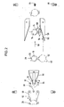
- the cover 16 is pivotally attached to a foot 22, which is arranged next to the dome 14 and is attached to the tank car 12, about an axis 20 which runs parallel to the direction of travel of the tank scale 12.
- a second base 24 is attached to the tank car outside the dome 14 and bears an axis 26 on which a locking arm 28 can be pivoted is appropriate.
- the axis 26 for the locking arm 28 also runs parallel to the direction of travel of the tank car 12.
- the plane in which the locking arm 28 can be pivoted runs essentially radially to the dome 14.
- the locking arm 28 is approximately radial in the direction of the dome 14 projecting projection 30 provided, which is dimensioned and arranged so that its lower limit 32 in the closed position shown in Fig. 3 of the cover 16 the latter at the edge thereof overlaps and thus secures in its closed position, in which the cover 16, possibly with the interposition of sealing elements, not shown in the drawing, bears tightly against the dome 14.
- the projection 30 is designed such that its boundary surface 34 located there slopes downward in the direction of the free end of the projection 30, that is to say in the direction of the central axis of the dome 14.
- the locking arm 28 is provided with an essentially vertical extension 36.
- the locking arm 28 is assigned a spring element 38 which acts on it in the direction of its effective position (FIGS. 3 and 6), in which the projection 30 engages over the edge of the cover 16.
- the lid 16 is provided at its edge with a projection 40 which, in the closed position of the lid, projects radially outward from the dome 14.
- a spring element designed as a helical spring 42 engages, which is attached next to the dome 14 and with its other end on the jacket or the like supports the tank car 12.
- This helical spring 42 acts on the cover 16 in the opening direction 44.
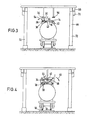
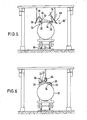
- the frame 46 shown in the drawing, bridging the track 10, is assigned to a station located between the levels IV-IV and V-V, in which the tank car 12, which can be one of several tank cars of an entire train, is filled.
- the tank car passes through the area before and after the filling station in the direction of arrow 48.
- the frame 46 carries some curve parts which serve to bring the lid 16 into the open position before the filling station is reached, so that the tank car fills through the filling opening 18 can be.
- the curve parts arranged behind the filling station in the direction of arrow 48 serve to bring the cover back into the closed position.
- the cooperating with the extension 36 of the locking arm 28 cam surface 52 of the first cam part 50 is arranged such that it moves the locking arm 28 around its axis 26 against the force of the spring 28 to the outside in the course of the movement of the tank car 12, that is, in the direction of the arrow 54 (Fig. 3) pivots until the projection 30 of the locking arm 28 comes out of engagement with the lid 16.
- the cover is slightly raised under the action of the spring element 42 assigned to it, which engages on the projection 40 of the cover, that is to say it is pivoted somewhat in the opening direction 44, by such a distance that the second curve part 56 in the course of the train the further movement of the tank car 12 in the direction of arrow 48 engages under the lid.
- the tank car 12 can now be filled.
- the tank car 12 comes in the course of its renewed movement in the direction of arrow 28 into the region of a third curve part 58, the curved surface 60 of which initially engages under the cover 16 in its open position and then in the course of the further travel movement due to its course via the vertical Dead center position pivots away, so that the cover 16 then falls back on the dome 14 in the direction of arrow 68.
- the locking arm 28 was pivoted back to Passie.ren of the first cam member 50 again under the action of the spring element 38 in its dome 14. facing end position somewhat pivoted outwards when the lid edge over the devisseiti q e obliquely extending boundary surface 34 of the projection 30 slides.
- a fourth curve part 64 which is embodied as a wheel or roller and acts on the surface of the cover 16, and engages it downwards in a tight system the seat of the dome 14 presses
- the closing arm 28 in the course of this last downward movement of the cover 16 into its final closed position is initially pivoted outward against the action of the spring 38 by the cover sliding along the upper boundary surface 34 of the projection 30 and then snaps back into its effective position as soon as the upper boundary surface of the cover 16 at the level of the lower boundary 32 of the projection 30 or is slightly below it. In this way, the cover 16 is locked again in its closed position by the closing arm 28.
- the path by which the locking arm can be pivoted by the spring 38 in the direction of the cover is limited by a stop or the like in such a way that, in its end position, it projects only so far into the range of movement of the cover that the latter in the course of the train its closing movement, the locking arm, apart from the projection 30, can pass unhindered.
- the curve parts 50, 56 and 58 are each arranged twice, so that it is not necessary to bring the tank wagons 12 of a train into a specific arrangement with respect to the position of the axis 20 and locking arm 28.
- the train after completion of the filling process against the direction of travel 28 through the area of the frame 46 and the curve parts attached to it to drive, it is expedient to arrange the upper region of the frame 46, which carries the curved parts, so that it can be raised and lowered.
- the two upper beams 66 which run parallel to the track 10 and to which the curve parts are attached via cross members 68, are attached to the vertical supports 72 in a suitable manner by means of hydraulic cylinders 70 or otherwise.
Landscapes
- Engineering & Computer Science (AREA)
- Mechanical Engineering (AREA)
- Cooling, Air Intake And Gas Exhaust, And Fuel Tank Arrangements In Propulsion Units (AREA)
- Filling Of Jars Or Cans And Processes For Cleaning And Sealing Jars (AREA)
- Beans For Foods Or Fodder (AREA)
- Casting Or Compression Moulding Of Plastics Or The Like (AREA)
- Sealing Of Jars (AREA)
- Closures For Containers (AREA)
Priority Applications (1)
| Application Number | Priority Date | Filing Date | Title |
|---|---|---|---|
| AT87106369T ATE64915T1 (de) | 1986-05-09 | 1987-04-30 | Vorrichtung zum betaetigen des verschlussdeckels der einfuelloeffnung eines kesselwagens. |
Applications Claiming Priority (2)
| Application Number | Priority Date | Filing Date | Title |
|---|---|---|---|
| DE19863615737 DE3615737A1 (de) | 1986-05-09 | 1986-05-09 | Vorrichtung zum betaetigen des verschlussdeckels der einfuelloeffnung eines kesselwagen |
| DE3615737 | 1986-05-09 |
Publications (3)
| Publication Number | Publication Date |
|---|---|
| EP0249726A2 true EP0249726A2 (fr) | 1987-12-23 |
| EP0249726A3 EP0249726A3 (en) | 1988-07-13 |
| EP0249726B1 EP0249726B1 (fr) | 1991-07-03 |
Family
ID=6300525
Family Applications (1)
| Application Number | Title | Priority Date | Filing Date |
|---|---|---|---|
| EP87106369A Expired - Lifetime EP0249726B1 (fr) | 1986-05-09 | 1987-04-30 | Dispositif pour actionner le couvercle de l'orifice de remplissage d'un wagon citerne |
Country Status (3)
| Country | Link |
|---|---|
| EP (1) | EP0249726B1 (fr) |
| AT (1) | ATE64915T1 (fr) |
| DE (1) | DE3615737A1 (fr) |
Cited By (1)
| Publication number | Priority date | Publication date | Assignee | Title |
|---|---|---|---|---|
| WO2002074581A1 (fr) * | 2001-03-19 | 2002-09-26 | Stag Ag | Dispositif de fermeture pour une tubulure de remplissage disposee sur un conteneur |
Families Citing this family (1)
| Publication number | Priority date | Publication date | Assignee | Title |
|---|---|---|---|---|
| DE102019104757B3 (de) * | 2019-02-25 | 2020-06-04 | Heinz-Jürgen Bornhorn | Zugangssystem für Eisenbahnkesselwagen, Verschubwagen und Verfahren zum Bereitstellen eines Zugangs |
Family Cites Families (7)
| Publication number | Priority date | Publication date | Assignee | Title |
|---|---|---|---|---|
| DE742653C (de) * | 1941-01-05 | 1943-12-09 | Bahnbedarf Ag | Deckelverschlussvorrichtung fuer Schuettgutbehaelter, insbesondere fuer Eisenbahnbehaelterwagen |
| US3260224A (en) * | 1964-10-07 | 1966-07-12 | Acf Ind Inc | Hatch cover structure |
| FR2223990A5 (fr) * | 1973-03-30 | 1974-10-25 | Automatisme Cie Gle | |
| FR2239404A1 (en) * | 1973-07-30 | 1975-02-28 | Automatisme Cie Gle | Control device for tank wagon filling device - has compressed air system moving along a gantry |
| GB2106061B (en) * | 1981-09-14 | 1984-11-07 | Reginald Friedenthal | Drop-bottom trucks and hoppers |
| DE3151244A1 (de) * | 1981-12-22 | 1983-06-30 | Schering Ag, 1000 Berlin Und 4619 Bergkamen | Vorrichtung fuer das automatische oeffnen und schliessen der deckel von transport- und behandlungstrommeln |
| DE3332749A1 (de) * | 1983-09-10 | 1985-03-28 | Ibau Hamburg Ingenieurgesellschaft Industriebau Mbh, 2000 Hamburg | Verfahren zum befuellen von kesselfahrzeugen, insbesondere mit schuettgut wie zement |
-
1986
- 1986-05-09 DE DE19863615737 patent/DE3615737A1/de active Granted
-
1987
- 1987-04-30 EP EP87106369A patent/EP0249726B1/fr not_active Expired - Lifetime
- 1987-04-30 AT AT87106369T patent/ATE64915T1/de not_active IP Right Cessation
Cited By (2)
| Publication number | Priority date | Publication date | Assignee | Title |
|---|---|---|---|---|
| WO2002074581A1 (fr) * | 2001-03-19 | 2002-09-26 | Stag Ag | Dispositif de fermeture pour une tubulure de remplissage disposee sur un conteneur |
| US6651708B2 (en) | 2001-03-19 | 2003-11-25 | Stag Ag | Closing device for a filling pipe arranged on a container |
Also Published As
| Publication number | Publication date |
|---|---|
| EP0249726B1 (fr) | 1991-07-03 |
| EP0249726A3 (en) | 1988-07-13 |
| DE3615737A1 (de) | 1987-11-12 |
| ATE64915T1 (de) | 1991-07-15 |
| DE3615737C2 (fr) | 1988-10-13 |
Similar Documents
| Publication | Publication Date | Title |
|---|---|---|
| EP0121086B1 (fr) | Wagon de marchandises ferroviaire | |
| DE3627871C2 (fr) | ||
| DE3808390A1 (de) | Tuerverriegelung fuer fahrzeuge, insbesondere fuer waggons mit schwenkschiebetueren | |
| EP0249726B1 (fr) | Dispositif pour actionner le couvercle de l'orifice de remplissage d'un wagon citerne | |
| DE2849516C2 (de) | Schiebewand für Güterwagen, Behälter o.dgl. | |
| EP0156143B1 (fr) | Disposition de montage de dispositifs de frein à sabot pour véhicules sur rails | |
| DE1605012C3 (de) | Fahrzeug, insbesondere Eisenbahnwagen mit aufklappbarem Dach | |
| DE3423610A1 (de) | Wahlweise nach unten oder oben zu oeffnende hecktuer fuer kraftfahrzeuge | |
| DE2412096A1 (de) | Anordnung zum aufladen insbesondere von alt- bzw. abfallpapier, wie zeitungen bzw. zeitschriften u. dgl. auf fahrzeuge | |
| DE2354776C2 (fr) | ||
| DE2735616C2 (de) | Vorrichtung zum Verschieben von Eisenbahnwagen | |
| DE3033298C2 (de) | Öffnungs- und Zuhaltevorrichtung für Deckel von Großraummüllbehältern | |
| EP0547448B1 (fr) | Véhicule ou conteneur, notamment wagon ferroviaire | |
| DE19746401C2 (de) | Müllsammelfahrzeug mit seitlich angeordneter Hub-/Kippvorrichtung | |
| EP0051243B1 (fr) | Dispositif pour faire basculer des poubelles, muni d'un dispositif pour ouvrir le couvercle | |
| AT409116B (de) | Anlage für den transport von schüttgut | |
| DE3304656C2 (fr) | ||
| DE2837699C2 (de) | Kupplung für schienengebundene Wagen | |
| DE2200348C3 (de) | Anlenkvorrichtung für einen lastabhängigen Bremskraftregler an Kraftfahrzeugen | |
| DE2701987A1 (de) | Strassenfahrzeug mit schwenkladegeraet und kippvorrichtung | |
| AT200065B (de) | An Müllabfuhrwagen anzubringende Mülltonnenentleerungsvorrichtung | |
| DE2634880A1 (de) | Lastkraftwagen mit vermindertem luftwiderstand | |
| DE3320802A1 (de) | Hebe- und transportgeraet fuer faesser od. dgl. | |
| DE1926298C3 (de) | Drehgestell, insbesondere verwindungsweiches Drehgestell für Schienenfahrzeuge, vorzugsweise für Reisezugwagen | |
| DE3134199A1 (de) | Hebevorrichtung fuer deckel von kernreaktordruckbehaeltern |
Legal Events
| Date | Code | Title | Description |
|---|---|---|---|
| PUAI | Public reference made under article 153(3) epc to a published international application that has entered the european phase |
Free format text: ORIGINAL CODE: 0009012 |
|
| AK | Designated contracting states |
Kind code of ref document: A2 Designated state(s): AT BE CH ES FR IT LI LU NL SE |
|
| PUAL | Search report despatched |
Free format text: ORIGINAL CODE: 0009013 |
|
| AK | Designated contracting states |
Kind code of ref document: A3 Designated state(s): AT BE CH ES FR IT LI LU NL SE |
|
| 17P | Request for examination filed |
Effective date: 19890107 |
|
| 17Q | First examination report despatched |
Effective date: 19900531 |
|
| ITF | It: translation for a ep patent filed | ||
| GRAA | (expected) grant |
Free format text: ORIGINAL CODE: 0009210 |
|
| AK | Designated contracting states |
Kind code of ref document: B1 Designated state(s): AT BE CH ES FR IT LI LU NL SE |
|
| PG25 | Lapsed in a contracting state [announced via postgrant information from national office to epo] |
Ref country code: NL Effective date: 19910703 Ref country code: BE Effective date: 19910703 |
|
| REF | Corresponds to: |
Ref document number: 64915 Country of ref document: AT Date of ref document: 19910715 Kind code of ref document: T |
|
| PG25 | Lapsed in a contracting state [announced via postgrant information from national office to epo] |
Ref country code: ES Free format text: LAPSE BECAUSE OF FAILURE TO SUBMIT A TRANSLATION OF THE DESCRIPTION OR TO PAY THE FEE WITHIN THE PRESCRIBED TIME-LIMIT Effective date: 19911014 |
|
| EN | Fr: translation not filed | ||
| PG25 | Lapsed in a contracting state [announced via postgrant information from national office to epo] |
Ref country code: FR Effective date: 19911122 |
|
| NLV1 | Nl: lapsed or annulled due to failure to fulfill the requirements of art. 29p and 29m of the patents act | ||
| PG25 | Lapsed in a contracting state [announced via postgrant information from national office to epo] |
Ref country code: LU Free format text: LAPSE BECAUSE OF NON-PAYMENT OF DUE FEES Effective date: 19920430 Ref country code: LI Effective date: 19920430 Ref country code: CH Effective date: 19920430 Ref country code: AT Effective date: 19920430 |
|
| PG25 | Lapsed in a contracting state [announced via postgrant information from national office to epo] |
Ref country code: SE Effective date: 19920501 |
|
| PLBE | No opposition filed within time limit |
Free format text: ORIGINAL CODE: 0009261 |
|
| STAA | Information on the status of an ep patent application or granted ep patent |
Free format text: STATUS: NO OPPOSITION FILED WITHIN TIME LIMIT |
|
| 26N | No opposition filed | ||
| REG | Reference to a national code |
Ref country code: CH Ref legal event code: PL |
|
| REG | Reference to a national code |
Ref country code: FR Ref legal event code: ST |
|
| EUG | Se: european patent has lapsed |
Ref document number: 87106369.9 Effective date: 19921204 |
|
| PG25 | Lapsed in a contracting state [announced via postgrant information from national office to epo] |
Ref country code: IT Free format text: LAPSE BECAUSE OF NON-PAYMENT OF DUE FEES Effective date: 20050430 |